Journal of Fuzzy Systems and Control, Vol. 1, No 3, 2023 |
|
PID-LQR Combined Linear Controller for Balancing Ballbot: Simulation and Experiment
Van-Dong-Hai Nguyen 1,*, Minh-Phuoc Cu 2, Tran-Minh-Nguyet Nguyen 3, Thanh-Do Huynh 4,
Dinh-Khoi Dang 5, Tan-Dat Hoang 6, Minh-Quan Nguyen 7, Dinh-Dung Vu 8, Chi-Hai-Duong Le 9,
Nguyen-Bao-Long Phan 10, Quoc-Duy Bui 11, Ngoc-Hai Le 12, Duy-Phuc Vo 13
1,3,4,5,6,7,8,9,10,11,12,13 Ho Chi Minh city University of Technology and Education (HCMUTE), Vietnam
2 Cao Thang College, Vietnam
Email: 1 hainvd@hcmute.edu.vn, 2 cuminhphuoc@caothang.edu.vn, 3 nguyetntm@hcmute.edu.vn,
4 20151083@student.hcmute.edu.vn, 5 20151385@student.hcmute.edu.vn, 6 20151349@student.hcmute.edu.vn,
7 20151312@student.hcmute.edu.vn, 8 20151259@student.hcmute.edu.vn, 9 20151354@student.hcmute.edu.vn,
10 20151057@student.hcmute.edu.vn, 11 20142294@student.hcmute.edu.vn, 12 20145490@student.hcmute.edu.vn,
13 20142389@student.hcmute.edu.vn
*Corresponding Author
Abstract—Ballbot is a robotic structure in which the robot self-balances on a ball by rotating wheels. This robot is a popular form of service robot. Developing controllers for this system provides academic tools for reality. In this paper, after presenting the dynamic equations of the ballbot, we design a Proportional Integrated Derivative (PID)-Linear Quadratic Regulator (LQR) combined (PID-LQR) controller to balance the robot on the ball. The simulation results show the success of this method. An experimental model of a ballbot is presented. In the experiment, PID-LQR combined controller also shows its ability to self-balancing for the ballbot. With this finding, a method of controlling this model is a reference for developing this service robot.
Keywords—Ballbot; Self-Balance; PID Control; LQR Control
Introduction
There are kinds of mobile robots [1]. Some robots do not need to be balanced control by using many wheels. But, the flexibility of these kinds of robots is not as good as a robot on a one-wheel [2] or on a ball [3] - ballbot. With the structure of a robot on a ball, it can smoothly turn itself around and move in multi-direction. Thence, it can be used as an indoor service robot [4]. However, due to the highly nonlinear characteristics of the ballbot, it is also widely studied in the academy. In Vietnam, the simulation of the linear controller for this robot is operated well with PID [5] and LQR [6], [7]. However, the experimental robot is not presented. Thence, an experimental survey is necessary to implement this direction in Vietnam.
Ballbot was presented first by Carnegie Mellon University [8]. It is a kind of robot in which the mechanical structure is designed to be self-balanced on a ball. Through the motion of its wheels, besides self-balancing on the ball, the ball can be controlled to move. But, in that research, the flexible mechanical structure with five DC motors makes the robot high and difficult to move. Thence, students at General Hsing University [9] make the hardware simpler with only three DC motors but the robot is still high and difficult to create. No balancing controller is considered in that study. Researchers in Tohoku Gakuin [8] developed a simpler structure of a ballbot that uses only three DC motors. Only the algorithm of tracking trajectory is the focus in this study, the balancing is not focused. In [10], the dynamic equations of the ballbot are systemized and presented. Thence, simulation for ballbot in 3D space becomes easier to generate. Even if this robot is developed, such as online identification [11] or using PSO-neural network [12], designing a simple, cheap model, in which a popular control chip is used, is still necessary. Therefore, in [13], a ballbot structure that uses Arduino is presented. The LQR method is presented in that research. However, system parameters are identified well in that reference. This condition is not ideal for other models. Then, a hybrid controller can be a solution for controlling a ballbot.
Ballbot is a complicated MIMO under-actuated system. It can be divided into smaller systems. Hence, each kind of controller can be applied to each smaller system. In this paper, we re-build the same hardware in which the electronics part is developed by us. Even though many control algorithms are tested well on this model, we want to apply a change in method to provide a hybrid controller to apply for our real model. Thence, we propose a PID-LQR combined controller for balancing this robot. The ability of our algorithm is proved to be good in both simulation and experiment. The main purpose of this research is to balance well this experimental robot. Therefore, the survey of this method and other methods is not considered in this study. However, through this study, hardware and software platforms are introduced for the next research in development methods for this model [14].
Dynamic Equations
The mathematical model of the ballbot is presented in Fig 1 a. General mechanical parts are shown in Fig. 1 b. Dynamic equations in this part inherit from [10]. Three symmetric DC motors are connected to a body. The axis of each motor is fixed to a wheel. Rotation of the axis of the motor makes the wheel rotate. These wheels rotate and keep the body balanced on the ball. The adhesion of the wheels and the ball is assumed to be remarkable and sliding friction is regarded as zero. System parameters are listed in column 1, 2 of Table 1. Values of system parameters are used from [10]. System variables shown in Table 2.
- System parameters
Parameters | Descriptions | Valuables and units |

| Mass of the ball | 2.2 kg |

| Mass of wheel | 0.555 kg |

| Mass of transmission mechanism | 0.160 kg |

| Mass of DC motor | 0.240 kg |

| Radius of ball | 0.115 m |

| Length of the body of the robot | 0.2 m |

| The total length of the body of the robot and the ball | 0.80 m |

| The height of the upper part of the body | 0.66 m |

| The height of the lower part of the body | 0.14 m |

| Inertial moment of the ball | 2.65.10-2 kgm2 |

| The inertial moment of the rotor of the motor | 2.42.10-2 kgm2 |

| Inertial moment of wheel | 6.94.10-2 kgm2 |

| Distance between center of ball and center of wheel | 0.405 m |

| Gravitation acceleration | 9.81 m/s2 |

| The angle between the wheel and the upper side of the ball | 450 |

| Horizontal angle of the wheel | 00 |

| Mass of body | 7.135 kg |

| Mass of the upper part of the body | 6.2 kg |

| Mass of the lower part of the body | 0.935 kg |

| Mass of the wheel | 0.995 kg |

| Radius of wheel | 0.050 m |

| Inertial moment of the axis of motor following coordinates yz/xz | 1.90.10-3 kgm2 |

| Inertial moment of the axis of motor following coordinates xy | 3.81.10-3 kgm2 |

| Inertial moment of the axis of motor following coordinates yz/x | 2.40 kgm2 |

| Inertial moment of the axis of motor following coordinates xy | 4.76.10-2 kgm2 |
- System variables
Parameters | Descriptions |

| The rotational angle of the body of the robot around axis j (j=x,y,z) |

| The rotational angle of Omni wheel i-th (i=1,2,3) |

| Rotational moment of Omni wheel i-th (i=1,2,3) |

| The rotational angle of the ball around axis j (j=x,y,z) |

| Rotational moment of assumed transmission wheel around axis j (j=x,y,z) |

| Assumed rotational moment of transmission wheel around axis j (j=x,y,z) |
- Structure of ballbot [10]

| 
|
(a)- Model on yz-plane | (b)-Model on xy-plane |
- Force analysis of 2D-model

- Rotational moment of ball on plane yx

- Rotational moment of body on plane yx

- Side view

- Up-down view
In Fig 2, we assume the ball does not rotate around axis z. We define:
| 
| (1) |
In Descartes's coordinate, we define the coordinate of each part of the robot as the ball (yS zS), body (yB zB), and wheel (yW zW).
| 
| (2) |
In-plane x-y, the axis of the coordinate is selected to be coincident with the center of the ball:
| 
| (3) |
Following coordinate yz/xz, we obtain formulas (4)-(9). The kinetic energy of the ball is:
| 
| (4) |
The ball is on the plane, then, we obtain:
| 
| (5) |
The kinetic energy of the body of the robot is:
| 
| (6) |
where: 
The kinetic energy of the body of the robot is:

| (7) |
The kinetic energy of the transmission wheel is:

| (8) |
where

The potential energy of the transmission wheel is:

| (9) |
External torque which is created by a moment of the motor is calculated as.
| 
| (10) |
Where 
In coordinator xy (Fig. 3, Fig. 4), the robot is kept balanced on the ball and the motion is rotated around axis z. Thence, the kinetic energy of the ball is
| 
| (11) |
The kinetic energy of the ball is:
| 
| (12) |
The kinetic energy of the wheel is:
| 
| (13) |
Where 
Relation of  and
and 

| (14) |
Thence, we obtain:

| (15) |
From (4) – (9), the Lagrangian operator is:

| (16) |

| (17) |
Dynamic equations of the system when considering plane yz/xz under the Euler-Lagrange method are:
Equations (), (), () can be described in matrix form as

| (21) |

| (22) |

where:  ;
;

 ;
;  ;
;
 ;
;  ;
;
Due to the complicated structure of the dynamic equation of the nonlinear form, we focus on the linear model (around the working point) to examine it. The values of a system for simulation are used in Table 1. Important variables to follow are which will be shown in () and ().
Variable matrix is defined as.

| (23) |
The equilibrium point is chosen as.
 ; ; 
| (24) |
Where is the input of the system. Thence, (), and () can be linearized around a working point in () to be.

| (25) |
Where:


With parameters in Table 1 and equilibrium point (), matrices A and B in () have values as
 
| (26) |
Variable matrix is defined as

| (27) |
Equation () is linearized around the working point to be:

| (28) |
Where 


Thence, linear dynamic equations of ballbot can be described in (), (), (). FB, i is the force created by a rotational moment of Omni wheel i (i=1,2,3). rB,I is the arm corresponding to FB, i. β is the angle between wheel Omni and vertical axis Oz. Respectively, β+2*pi/3 and β-2*pi/3 are angles between Omni 2, 3, and vertical axis Oz. In Fig. 5, and Fig. 6, the moment vector of rotational forces is:

| (29) |

| (30) |
Forces created by Omni are:
The lengths of the arms are:
From (), to (), rotational moments (of the body of the robot) that are controlled in a real model are:
Forces that are created by the “assumed” wheel on the body of the robot are:
Lengths of arms are:
Thence, moments created by the body of the robot are:
Matrices that describe the relation between the moment of motor and equivalent assumed moments affecting the ballbot are shown in () and ().

| (37) |

| (38) |
From the nonlinear model, around the equilibrium point, transfer functions can be examined to make the survey on the system easier. With the parameters in Table 1, the transfer functions of the system in plane yz are:
Control Design
A unique big LQR controller can be designed for a MIMO under-actuated model, such as a ballbot. However, it could be complicated. Therefore, we propose a combined PID and LQR controller as in Fig. 7. Therefore, one big controller can be divided into smaller controllers. One LQR controller is used to control θx and ψx. One LQR controller is used to control θy and ψy. Two LQR controllers are chosen to have the same control parameters. The weighing matrices are selected as.

| (43) |
From (), (), using Matlab function.

| (44) |
Then, we obtain:

| (45) |
One PID controller is used to control ψz due to its simple linear structure and its popularity in the academy and industry. Its parameters are:

| (46) |
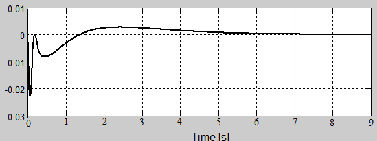
Some simulation results are shown in Fig. 8 to Fig. 10. Three important variables that we focus on are θx, ψx, ψy. The balance of the ballbot can be assured if these variables are controlled well. In Fig. 8, angle θx is stabilized after 0.2 s. Vibration is around from -0.5 rad to 0.2 rad. In Fig. 9, angle ψx is stabilized after 8s. Vibration is around -0.025 rad to 0.005 rad. In Fig. 10, angle ψz is stabilized after 8s. Vibration is around -1.5 rad to 2.5 rad. In simulation, the system is balanced well. However, the wide vibration in Fig. 10 shows the difficulty of applying a controller in simulation to a real experiment.

- Structure of controller’s structure for ballbot (described by Matlab blocks)
Our method is designed to prove the ability to use this control structure to stabilize a well ballbot at an equilibrium point to implement a new control structure for this model. The methods of only PID or only LQR are not built by us successfully to be compared to our method. Thence, simulation, and experiment in this paper are approved to show the success of the combined method.
Simulation
Some simulation results are shown in Fig. 8 to Fig. 10. Three important variables that we focus on are θx, ψx, ψy. The balance of the ballbot can be assured if these variables are controlled well. In Fig. 8, angle θx is stabilized after 0.2 s. Vibration is around from -0.5 rad to 0.2 rad. In Fig. 9, angle ψx is stabilized after 8s. Vibration is around -0.025 rad to 0.005 rad. In Fig. 10, angle ψz is stabilized after 8s. Vibration is around -1.5 rad to 2.5 rad. In simulation, the system is balanced well. However, the wide vibration in Fig. 10 shows the difficulty of applying a controller in simulation to a real experiment. These figures show the stability of the ballbot at the equilibrium point through values moving to zero of these variables. The stability is vulnerable and control parameters must be improved through future research.

- Angle θx (rad)
- Angle ψx (rad)

- Angle ψz (rad)
In the simulation, only the stability of the system is shown. Control parameters are chosen as trial-and-error tests. Different control parameters make the system unstable. Thence, no survey is shown in this study. Therefore, calibration rules are a task for the future.
Experiment
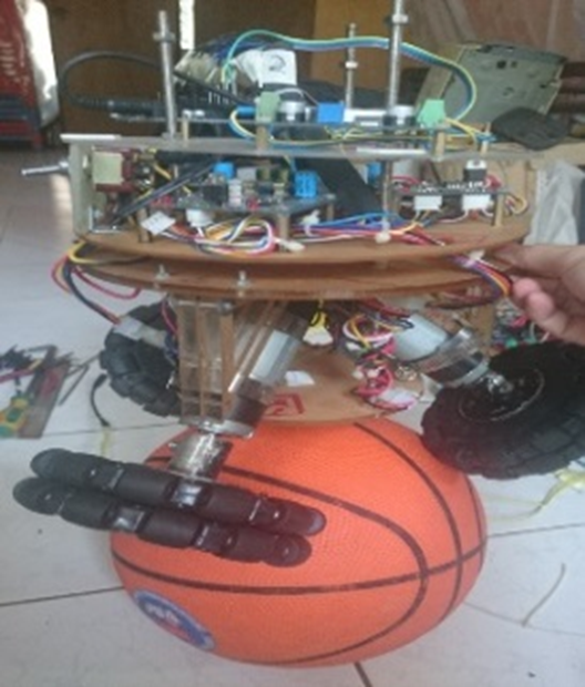
A real model is built as in Fig. 11 and Fig. 12. The experimental structure for the system is shown in Fig. 13. Testing the exactness of the tilt angle measured by the IMU sensor, we use the Kalman filter to filter the noise and obtain Fig. 14. In that figure, the data with noise from IMU is blue and the data after being filtered is in red. The Kalman filter works well to make the signal smoother.
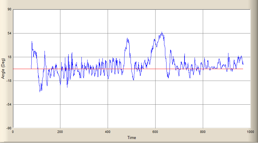
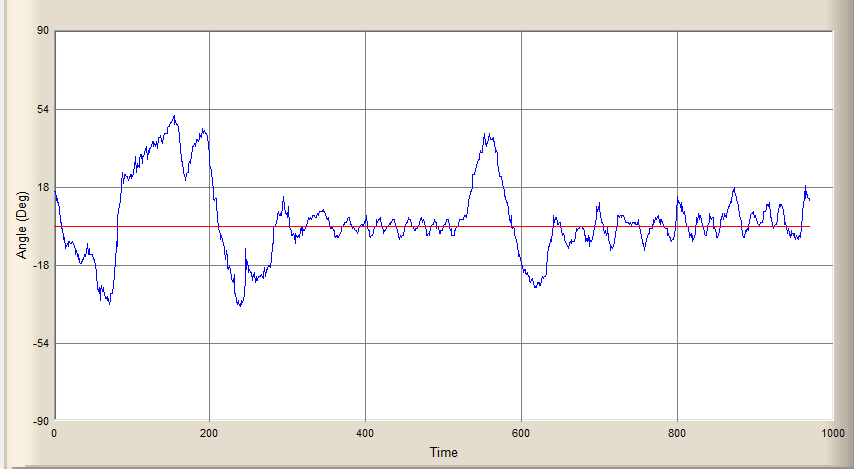
The important variables of ballbot ψx and ψy are measured and shown in Fig. 15 and Fig. 16. In Fig. 15, angle ψx oscillates around -30 degrees to 54 degrees. In Fig. 16, angle ψz oscillates around -30 degrees to 54 degrees. The robot oscillates hard but balances in 1 second before falling. The robot can be balanced in 1 second before falling. The balancing time is short and should be improved.

- Experimental ballbot
- Ballbot on ball

- Experimental structure of ballbot hardware
Thence, the PID-LQR controller can balance the system at an equilibrium point. However, system responses are not the same in simulation and experiment. This study only proves that PID-LQR is acceptable for this model. Our experimental model is shown in the link: https://www.youtube.com/watch?v=6ibiqnzVN0o.

- Signal from IMU (blue) and after being filtered by Kalman filter (red) through time (ms)
- Angle ψx (degree) in blue, compared to set point zero in red through time (ms)
- Angle ψz (degree) in blue, compared to set point zero in red through time (ms)
Conclusion
In the paper, we analyze the dynamic equations of the ballbot. Therefore, a combined PID-LQR controller for balancing this system on the equilibrium point is designed and tested well on simulation. We build a real model for the laboratory and describe our platform in paper. The experimental results show that our ballbot can balance within 1 sec before falling. Therefore, our method is implemented method for future research due to its operation in both simulation and experiment. This method is a reference for applied methods in theory and reality. Moreover, this proposed hardware is the basement of the ballbot for another laboratory research. Our finding provides a new tool to stabilize the ballbot by providing a new method (PID_LQR combined structure). Therefore, this model can work with better quality. We can develop it to be a service robot in the laboratory for study and research. Therefore, a service robot is useful for restaurants and logistic centers due to its flexibility in motion. However, control parameters in this study are chosen through trial-and-error tests. And different control parameters cannot keep the system balanced. Therefore, a rule to choose and calibrate these parameters is necessary for the future. Moreover, both simulation and experiment show the ability of the controller, but the responses are different. Therefore, system parameters must be identified in future development.
Acknowledgment
This paper belongs to project T2023-60, funded by Ho Chi Minh City University of Technology and Education (HCMUTE). We are grateful for this support.
References
- S. Tarao, Y. Fujiwara, N. Tsuda and S. Takata, “Development of Autonomous Mobile Robot Platform Equipped with a Drive Unit Consisting of Low-End In-Wheel Motors,” 2020 5th International Conference on Control and Robotics Engineering (ICCRE), pp. 42-47, 2020, https://doi.org/10.1109/ICCRE49379.2020.9096433.
- Q. Voortman, D. Efimov, A. Pogromsky, H. Silm, J. -P. Richard and H. Nijmeijer, “Observing a Unicycle Robot with Data Rate Constraints: a Case Study,” 2021 60th IEEE Conference on Decision and Control (CDC), pp. 1765-1770, 2021, https://doi.org/10.1109/CDC45484.2021.9683052.
- J. Shen and D. Hong, “OmBURo: A Novel Unicycle Robot with Active Omnidirectional Wheel,” 2020 IEEE International Conference on Robotics and Automation (ICRA), pp. 8237-8243, 2020, https://doi.org/10.1109/ICRA40945.2020.9196927.
- S. Srivatchan, “Development of a Balancing Robot as an Indoor Service Agent,” Carnegie Mellon University, 2020, https://www.ri.cmu.edu/app/uploads/2020/12/ssrivatc_thesis_document.pdf.
- C. Cai, J. Lu and Z. Li, “Kinematic Analysis and Control Algorithm for the Ballbot,” IEEE Access, vol. 7, pp. 38314-38321, 2019, https://doi.org/10.1109/ACCESS.2019.2902219.
- M. Studt, I. Zhavzharov and H. S. Abbas, “Parameter Identification and LQR/MPC Balancing Control of a Ballbot,” 2022 European Control Conference (ECC), pp. 1315-1321, 2022, https://doi.org/10.23919/ECC55457.2022.9837996.
- Z. Li and R. Hollis, “Toward A Ballbot for Physically Leading People: A Human-Centered Approach,” 2019 IEEE/RSJ International Conference on Intelligent Robots and Systems (IROS), pp. 4827-4833, 2019, https://doi.org/10.1109/IROS40897.2019.8968546.
- T. B. Lauwers, G. A. Kantor and R. L. Hollis, “A dynamically stable single-wheeled mobile robot with inverse mouse-ball drive,” Proceedings 2006 IEEE International Conference on Robotics and Automation, 2006. ICRA 2006., pp. 2884-2889, 2006, https://doi.org/10.1109/ROBOT.2006.1642139.
- M. Kumagai and T. Ochiai, “Development of a robot balancing on a ball,” 2008 International Conference on Control, Automation and Systems, pp. 433-438, 2008, https://doi.org/10.1109/ICCAS.2008.4694680.
- B. Su, T. Wang, S. Kuang, J. Wang, “Effects of physical parameters on the dynamic behavior of ballbot-like robots,” International Journal of Robotics and Automation, vol. 29, no. 1, pp. 105-115, 2014, http://dx.doi.org/10.2316/Journal.206.2014.1.206-3957.
- K. V. D. Blonk, “Modeling and Control of a Ball-Balancing Robot,” Internship & Master thesis at ALTEN Mechatronics, pp.2-25, 2014, https://essay.utwente.nl/65559/1/vanderBlonk_MSc_EEMCS.pdf
- D. Ba Pham et al., “Balancing and Tracking Control of Ballbot Mobile Robots Using a Novel Synchronization Controller Along With Online System Identification,” IEEE Transactions on Industrial Electronics, vol. 70, no. 1, pp. 657-668, 2023, https://doi.org/10.1109/TIE.2022.3146642.
- M. Shaheer et al., “Control of a ball-bot using a PSO trained neural network,” 2016 2nd International Conference on Control, Automation and Robotics (ICCAR), pp. 24-28, 2016, https://doi.org/10.1109/ICCAR.2016.7486692.
- E. P. Mocherlla, W. Netto and S. Jesna, “Design of LQR controller for Ballbot and hardware implementation,” 2017 9th International Conference on Information Technology and Electrical Engineering (ICITEE), pp. 1-6, 2017, https://doi.org/10.1109/ICITEED.2017.8250491.
Van-Dong-Hai Nguyen, PID-LQR Combined Linear Controller for Balancing Ballbot: Simulation and Experiment









