Journal of Fuzzy Systems and Control, Vol. x, No x, 202x |
Stroke Patient Communication Tool with Touch Sensor and Phrase Time Step
Fajar Aji Pratama 1, Meilia Safitri 2,*, Erika Loniza 3, Henry Probo Santoso 4
1,2,3 Department of Medical Electronics Technology, Universitas Muhammadiyah Yogyakarta, Yogyakarta, Indonesia
4 Robotic and Autonomous Systems, University of Sussex, United Kingdom
Email: 1 fajaraji52564@gmail.com, 2 meilia.safitri@vokasi.umy.ac.id, 3 erika@umy.ac.id, 4 hs628@sussex.ac.uk
*Corresponding Author
Abstract—The purpose of this prototype is to enhance communication between stroke patients and their caregivers, as difficulty in understanding the nuanced wishes of stroke patients often leads to a reduced quality of life for the patients and increased caregiver depression. This study aimed to address these challenges by providing a more effective means of interpreting the desires of stroke patients during their interactions with their caregivers. The prototype utilizes a dual-input system to capture the intricate communication dynamics. The first input involves recording the finger movements of the patient through touch interaction with the TTP223 touch sensor area. In contrast, the second input comprises a time-step phrase that serves as a complementary mechanism for selecting communication phrases. The combination of these inputs is processed using Boolean logic, specifically employing basic AND logic, in which both inputs must register as high to yield a correspondingly high output. The ESP32 microcontroller processes the output signal, and the resulting information is displayed on both an LCD screen and a dedicated Telegram application. The prototype achieved a notable accomplishment of 100% accuracy in reading inputs.
Keywords—Stroke Patient; TTP 223 Touch Sensor; Boolean Logic
Stroke is widely regarded as a serious medical condition. It arises from the obstruction or narrowing of blood vessels supplying blood and oxygen to the brain, or from the rupture of these vessels [1]. Disruptions in blood vessel function can give rise to a range of common impairments associated with stroke, including physical, emotional, and cognitive [2]. Physical impairments can manifest as limitations in the movement of various body parts [3]. Emotional disturbances encompass both psychological and physiological states and reactions [4]. Furthermore, cognitive impairment can have significant consequences for carrying out daily activities [5]. These disturbances can also make communication in post-stroke patients more challenging [6].
The interaction between stroke patients and their caregivers is challenging, both for the patient and the caregiver, and vice versa [7]. These difficulties can cause depression in both caregivers and stroke patients due to the reduced quality of life of stroke patients resulting from emotional and mental disturbances, among other factors [8]. Caregivers’ difficulty in interpreting or understanding a patient's wishes becomes a serious issue in this case [9]. However, these challenges can be addressed by helping stroke patients express their desires and create true and false situations to choose the phrases they want using Boolean logic.
In the era of globalization, rapid technological advancements have transformed human life. Logical calculations are the foundation of computer systems that are useful for human life owing to their precision and accuracy [10]. In classical logic, a statement can be either true or false and interpreted in binary logic as 0/1 [11].
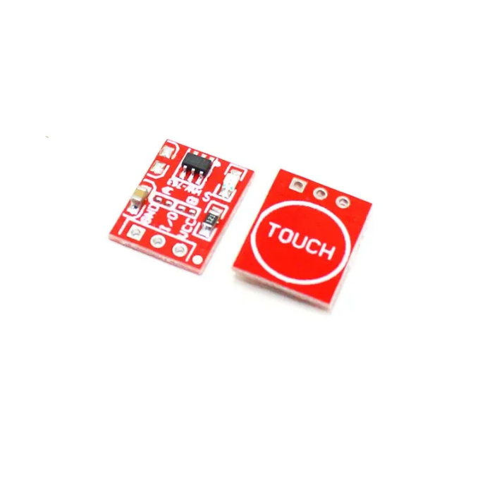
Boolean algebra is widely used to address and resolve various practical issues. As a result, the incorporation of Boolean algebra into programming systems is fundamental to daily life [12]. The application of Boolean logic in this device facilitates the selection of phrases, as there is only true or false logic in the output readings [10]. The reading input employed involves the TTP223 touch sensor for the communication phrase selection mode switch and a 3-second phrase time step for the selection of phrases displayed on the LCD. Placing a finger on the sensor area results in a high logic output from the sensor, whereas the absence of touch results in a low logic output [13].
Considering the identified challenges, a prototype is required to enhance communication for stroke patients and enable caregivers to comprehend the preferences of stroke patients more effectively.
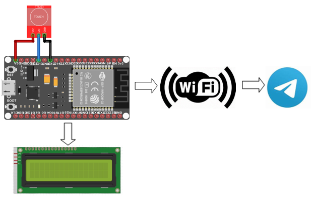
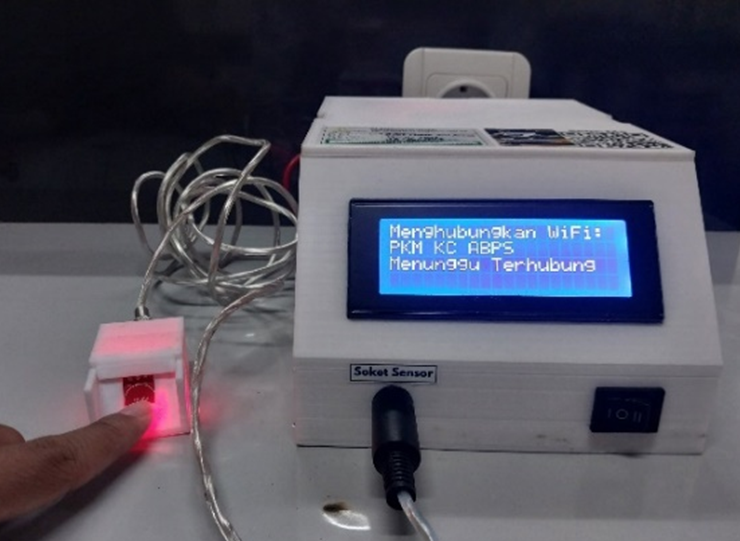
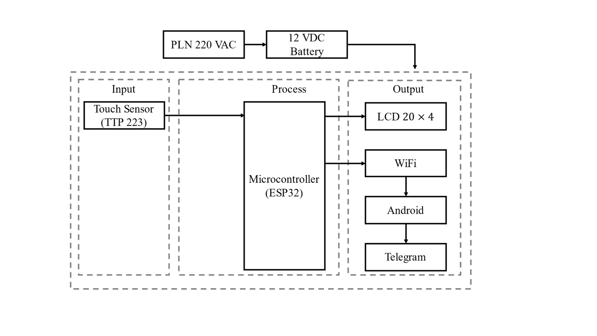
The working circuit of the prototype system is illustrated in Fig. 1. When the device is powered on, initialization occurs, and the battery power supplies the minimum system circuitry causing the LCD to display the connection status of the device to the Wi-Fi. Once connected to Wi-Fi, the device was ready for use. To use this device, the patient can touch their finger to the TTP223 touch sensor area and adhere to the specified time step for the communication phrase. After the sensor area is touched and the time step is met, the communication phrase is displayed on the LCD and transmitted to the Telegram application through Wi-Fi serial communication.
The power supply (12 VDC battery) served as the DC voltage supply for the entire circuit, where the utilized battery could be recharged using an adapter with an input voltage of 220 VAC and an output voltage of 12 VDC at 2 A. In the input section, there is a TTP223 touch sensor with an additional phrase interval set on the microcontroller. The touch sensor functions as an interface for selecting the phrases desired by the patient, displaying the selected phrase on the character LCD based on the needs of post-stroke patients [14]. After the input was received by the sensor, the signal was processed by the ESP32 microcontroller. After processing, the selected communication phrase is displayed on a 20 × 4-character LCD and transmitted to the Telegram application through Wi-Fi serial communication.
The minimum system circuitry reads the input generated from the touch-sensor area. The input from the touch sensor is in the form of high/low logic, where touching the sensor with the patient's finger generates high/1 logic, and when not touched, it produces low/0 logic. The resulting input is combined with the time-step input for each phrase, where each phrase has a 3-second time window for selection. The minimum system circuitry can be observed in Fig. 2.

The Boolean algebra method was used for the two defined inputs. Boolean algebra uses binary variables and logical operations. The binary variables are represented by three basic logic operations: AND logic, OR logic, and NOT logic. Boolean functions consist of binary variables that represent functions and an algebraic expression created using binary variables with numbers 0 and 1 as well as logical operation symbols. The result of Boolean logic can be expressed in a truth table obtained from combinations of binary numbers 0/1 that can produce different outputs for each combination [11]. The truth table for the AND logic is presented in Table 1.
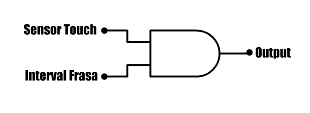
In the prototype created, this study utilized the basic AND logic operation, where all AND logic inputs must be high/1 to produce a high/1 output, and if any/all inputs are low, then the AND logic output is 0/low [11]. The AND logic equation is (Y = A AND B). The symbol for AND logic with two inputs and one output is shown in Fig. 3.
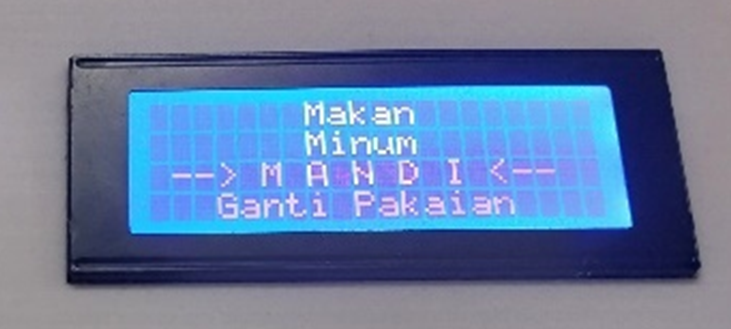
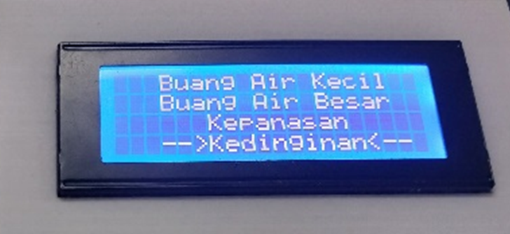
There are eight phrases used in this prototype, consisting of fundamental statements such as “I want to eat,” “I want to drink,” and “I want to bathe” [14]. Additional phrases, tailored to the needs of stroke patients, were displayed on a -character LCD. The appearance of these phrases can be observed in Fig. 4 and Fig. 5.
Input | Output | |
A | B | |
0 | 0 | 0 |
0 | 1 | 0 |
1 | 0 | 0 |
1 | 1 | 1 |
There are two inputs to this prototype: touch on the touch sensor area and a phrase time step set on the microcontroller. Utilizing a predetermined time interval of 3 s for each phrase, the writer employs the phrase reading interval as input 1, and input 2 is associated with the touch on the touch sensor area. When both inputs of the AND logic are obtained, an output is generated according to the predefined conditions. The conditions are listed in Table 2.
From the Input and Output specifications table, the device sends an output according to predefined input conditions. A high output symbolizes a phrase transmitted in accordance with a specified table. If these conditions are not met, the output cannot be sent or processed, resulting in a 0/Low output. An output of 1/High indicates that the AND logic receives a high logic in both its inputs, namely, the touch on the touch sensor area and the Time Step for the phrase. If the output is 0/Low, it signifies that the AND logic input does not receive high logic in one or both of its inputs. After obtaining the AND logic output signal, the logic result is sent to the signal processor and the ESP32 microcontroller. Subsequently, the signal reading result is output as a communication phrase on the 20 × 4-character LCD and the Telegram application according to the specified Input and Output table.
Frasa | Input | Output | |
Touch Sensor | Phrase Time Step (s) | ||
I want to Eat | ON | 0 – 2.99 sec | 1/High |
I Want to Drink | ON | 3 – 5.99 sec | 1/High |
I Want to Bath | ON | 6 – 9.99 sec | 1/High |
I Want to Defecate | ON | 9 – 12.9 sec | 1/High |
I Want to Urinate | ON | 12–15.9 sec | 1/High |
I Am Feeling Cold | ON | 15–18.9 sec | 1/High |
I Am Feeling Hot | ON | 18–21.9 sec | 1/High |
I Want to Change Clothes | ON | 21–24.9 sec | 1/High |
The TTP223 touch sensor, as shown in Fig. 6, is a type of capacitive touch sensor known for its high accuracy. It utilizes the skin contact with the sensor area to obtain the sensor output [13]. The sensor output is in the form of digital signals, symbolized by numbers 1 and 0, or high and low.
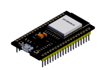
ESP32 functions as a processor for digital signal readings from the TTP 223 touch sensor. The processing in ESP32 includes Wi-Fi connectivity for serial communication and subsequent linkage to the Telegram application. As illustrated in Fig. 7, ESP32 is an affordable system-on-chip (SoC) microcontroller developed by Espressif Systems, the developer of the ESP8266, also known as NodeMCU. The ESP32 is built with a 32-bit Tensilica Xtensa LX6 microprocessor that incorporates integrated Wi-Fi and Bluetooth [16]. It operated with a specified input and an operational voltage of 5 volts. The microcontroller features 18 ADC pins, two DAC pins, 128 KB of flash memory, a clock speed of 240 MHz, and integrated communication capabilities such as Wi-Fi, Bluetooth, I2C, SPI, and Serial [17].
The utilized Touch Sensor is one of the touch sensors that rely on fingertip contact with the sensor area, generating binary logic 1/0 that functions as an input for the device. Meanwhile, on the ESP32 board, which serves as the signal processor, the output is displayed on a 20 × 4-character LCD and transmitted to Telegram through Wi-Fi serial communication. This is illustrated in Fig. 7. Consequently, it produces a prototype device that aids in communication for stroke patients, as shown in Fig. 8.
The test involved 10 respondents who were asked to use the prototype, with five repetitions for each phrase. In the output table, the numeral 1 signifies that the output sent the phrase in accordance with predefined conditions from the input readings when the sensor was touched, and the input interval adhered to the specifications in Table 2 (Input and Output conditions). The numeral 0 indicates that the output from the device did not receive the corresponding inputs, resulting in the device not transmitting the communication phrase to the signal processor. Consequently, the output was not sent to the LCD or Telegram. Description of the communication phase outputs.
The results obtained after testing on respondent 1 indicate that the prototype functions well, can transmit communication phrases according to the Table 3 provisions, and achieves a sensor reading and interval accuracy of 100%. The results obtained after testing on respondent 2 indicate that the prototype functions well, can transmit communication phrases according to the Table 4 provisions, and achieves a sensor reading and interval accuracy of 100%. The results obtained after testing on respondent 3 indicate that the prototype functions well, can transmit communication phrases according to the Table 5 provisions, and achieves a sensor reading and interval accuracy of 100%.
No | Input | Output | ||||||||
Time Step (s) | Sensor Touch | F1 | F2 | F3 | F4 | F5 | F6 | F7 | F8 | |
1 | 2nd | High | 1 | 0 | 0 | 0 | 0 | 0 | 0 | 0 |
5th | High | 0 | 1 | 0 | 0 | 0 | 0 | 0 | 0 | |
6th | High | 0 | 0 | 1 | 0 | 0 | 0 | 0 | 0 | |
22th | High | 0 | 0 | 0 | 0 | 0 | 0 | 0 | 1 | |
20th | High | 0 | 0 | 0 | 0 | 0 | 0 | 1 | 0 | |
18th | High | 0 | 0 | 0 | 0 | 0 | 1 | 0 | 0 | |
10th | High | 0 | 0 | 0 | 1 | 0 | 0 | 0 | 0 | |
14th | High | 0 | 0 | 0 | 0 | 1 | 0 | 0 | 0 | |
No | Input | Output | ||||||||
Time Step (s) | Sensor Touch | F1 | F2 | F3 | F4 | F5 | F6 | F7 | F8 | |
2 | 17th | High | 0 | 0 | 0 | 0 | 0 | 1 | 0 | 0 |
15th | High | 0 | 0 | 0 | 0 | 1 | 0 | 0 | 0 | |
6th | High | 0 | 1 | 0 | 0 | 0 | 0 | 0 | 0 | |
3nd | High | 1 | 0 | 0 | 0 | 0 | 0 | 0 | 0 | |
9th | High | 0 | 0 | 1 | 0 | 0 | 0 | 0 | 0 | |
24th | High | 0 | 0 | 0 | 0 | 0 | 0 | 0 | 1 | |
11th | High | 0 | 0 | 0 | 1 | 0 | 0 | 0 | 0 | |
21th | High | 0 | 0 | 0 | 0 | 0 | 0 | 1 | 0 | |
No | Input | Output | ||||||||
Time Step (s) | Sensor Touch | F1 | F2 | F3 | F4 | F5 | F6 | F7 | F8 | |
3 | 6.5th | High | 0 | 0 | 1 | 0 | 0 | 0 | 0 | 0 |
1st | High | 1 | 0 | 0 | 0 | 0 | 0 | 0 | 0 | |
20th | High | 0 | 0 | 0 | 0 | 0 | 0 | 1 | 0 | |
20th | High | 0 | 0 | 0 | 0 | 0 | 0 | 0 | 1 | |
5.5th | High | 0 | 1 | 0 | 0 | 0 | 0 | 0 | 0 | |
10th | High | 0 | 0 | 0 | 1 | 0 | 0 | 0 | 0 | |
17th | High | 0 | 0 | 0 | 0 | 0 | 1 | 0 | 0 | |
13th | High | 0 | 0 | 0 | 0 | 1 | 0 | 0 | 0 | |
The results obtained after testing on respondent 4 indicate that the prototype functions well, can transmit communication phrases according to the Table 6 provisions, and achieves a sensor reading and interval accuracy of 100%. The results obtained after testing on respondent 5 indicate that the prototype functions well, can transmit communication phrases according to the Table 7 provisions, and achieves a sensor reading and interval accuracy of 100%. The results obtained after testing on respondent 6 indicate that the prototype functions well, can transmit communication phrases according to the Table 8 provisions, and achieves a sensor reading and interval accuracy of 100%.
No | Input | Output | ||||||||
Time Step (s) | Sensor Touch | F1 | F2 | F3 | F4 | F5 | F6 | F7 | F8 | |
4 | 2nd | High | 1 | 0 | 0 | 0 | 0 | 0 | 0 | 0 |
22th | High | 0 | 0 | 0 | 0 | 0 | 0 | 0 | 1 | |
4.1th | High | 0 | 1 | 0 | 0 | 0 | 0 | 0 | 0 | |
19th | High | 0 | 0 | 0 | 0 | 0 | 0 | 1 | 0 | |
7th | High | 0 | 0 | 1 | 0 | 0 | 0 | 0 | 0 | |
17th | High | 0 | 0 | 0 | 0 | 0 | 1 | 0 | 0 | |
14th | High | 0 | 0 | 0 | 0 | 1 | 0 | 0 | 0 | |
9.8th | High | 0 | 0 | 0 | 1 | 0 | 0 | 0 | 0 | |
No | Input | Output | ||||||||
Time Step (s) | Sensor Touch | F1 | F2 | F3 | F4 | F5 | F6 | F7 | F8 | |
5 | 10th | High | 0 | 0 | 0 | 1 | 0 | 0 | 0 | 0 |
15th | High | 0 | 0 | 0 | 0 | 1 | 0 | 0 | 0 | |
6th | High | 0 | 1 | 0 | 0 | 0 | 0 | 0 | 0 | |
3nd | High | 1 | 0 | 0 | 0 | 0 | 0 | 0 | 0 | |
9th | High | 0 | 0 | 1 | 0 | 0 | 0 | 0 | 0 | |
24th | High | 0 | 0 | 0 | 0 | 0 | 0 | 0 | 1 | |
17th | High | 0 | 0 | 0 | 0 | 0 | 1 | 0 | 0 | |
21th | High | 0 | 0 | 0 | 0 | 0 | 0 | 1 | 0 | |
No | Input | Output | ||||||||
Time Step (s) | Sensor Touch | F1 | F2 | F3 | F4 | F5 | F6 | F7 | F8 | |
6 | 14th | High | 0 | 0 | 0 | 0 | 1 | 0 | 0 | 0 |
11th | High | 0 | 0 | 0 | 1 | 0 | 0 | 0 | 0 | |
22th | High | 0 | 0 | 0 | 0 | 0 | 0 | 0 | 1 | |
5.7th | High | 0 | 1 | 0 | 0 | 0 | 0 | 0 | 0 | |
2nd | High | 1 | 0 | 0 | 0 | 0 | 0 | 0 | 0 | |
20th | High | 0 | 0 | 0 | 0 | 0 | 0 | 1 | 0 | |
8.5th | High | 0 | 0 | 1 | 0 | 0 | 0 | 0 | 0 | |
16th | High | 0 | 0 | 0 | 0 | 0 | 1 | 0 | 0 | |
No | Input | Output | ||||||||
Time Step(s) | Sensor Touch | F1 | F2 | F3 | F4 | F5 | F6 | F7 | F8 | |
7 | 21th | High | 0 | 0 | 0 | 0 | 0 | 0 | 1 | 0 |
17th | High | 0 | 0 | 0 | 0 | 0 | 1 | 0 | 0 | |
24th | High | 0 | 0 | 0 | 0 | 0 | 0 | 0 | 1 | |
1st | High | 1 | 0 | 0 | 0 | 0 | 0 | 0 | 0 | |
7.2th | High | 0 | 0 | 1 | 0 | 0 | 0 | 0 | 0 | |
5.5th | High | 0 | 1 | 0 | 0 | 0 | 0 | 0 | 0 | |
11th | High | 0 | 0 | 0 | 1 | 0 | 0 | 0 | 0 | |
14th | High | 0 | 0 | 0 | 0 | 1 | 0 | 0 | 0 | |
The results obtained after testing on respondent 7 indicate that the prototype functions well, can transmit communication phrases according to the Table 9 provisions, and achieves a sensor reading and interval accuracy of 100%. The results obtained after testing on respondent 8 indicate that the prototype functions well, can transmit communication phrases according to the Table 10 provisions, and achieves a sensor reading and interval accuracy of 100%. The results obtained after testing on respondent 9 indicate that the prototype functions well, can transmit communication phrases according to the Table 11 provisions, and achieves a sensor reading and interval accuracy of 100%.
No | Input | Output | ||||||||
Time Step (s) | Sensor Touch | F1 | F2 | F3 | F4 | F5 | F6 | F7 | F8 | |
8 | 23th | High | 0 | 0 | 0 | 0 | 0 | 0 | 0 | 1 |
15th | High | 0 | 0 | 0 | 0 | 1 | 0 | 0 | 0 | |
2nd | High | 1 | 0 | 0 | 0 | 0 | 0 | 0 | 0 | |
9.5th | High | 0 | 0 | 0 | 1 | 0 | 0 | 0 | 0 | |
4th | High | 0 | 1 | 0 | 0 | 0 | 0 | 0 | 0 | |
7.5th | High | 0 | 0 | 1 | 0 | 0 | 0 | 0 | 0 | |
18th | High | 0 | 0 | 0 | 0 | 0 | 0 | 1 | 0 | |
16th | High | 0 | 0 | 0 | 0 | 0 | 1 | 0 | 0 | |
No | Input | Output | ||||||||
Time Step (s) | Sensor Touch | F1 | F2 | F3 | F4 | F5 | F6 | F7 | F8 | |
9 | 4th | High | 0 | 1 | 0 | 0 | 0 | 0 | 0 | 0 |
11th | High | 0 | 0 | 0 | 1 | 0 | 0 | 0 | 0 | |
2nd | High | 1 | 0 | 0 | 0 | 0 | 0 | 0 | 0 | |
17th | High | 0 | 0 | 0 | 0 | 0 | 1 | 0 | 0 | |
13th | High | 0 | 0 | 0 | 0 | 1 | 0 | 0 | 0 | |
24th | High | 0 | 0 | 0 | 0 | 0 | 0 | 0 | 1 | |
8th | High | 0 | 0 | 1 | 0 | 0 | 0 | 0 | 0 | |
19th | High | 0 | 0 | 0 | 0 | 0 | 0 | 1 | 0 | |
No | Input | Output | ||||||||
Time Step (s) | Sensor Touch | F1 | F2 | F3 | F4 | F5 | F6 | F7 | F8 | |
10 | 23th | High | 0 | 0 | 0 | 0 | 0 | 0 | 0 | 1 |
5th | High | 0 | 1 | 0 | 0 | 0 | 0 | 0 | 0 | |
10th | High | 0 | 0 | 0 | 1 | 0 | 0 | 0 | 0 | |
16th | High | 0 | 0 | 0 | 0 | 0 | 1 | 0 | 0 | |
1st | High | 1 | 0 | 0 | 0 | 0 | 0 | 0 | 0 | |
20th | High | 0 | 0 | 0 | 0 | 0 | 0 | 1 | 0 | |
7th | High | 0 | 0 | 1 | 0 | 0 | 0 | 0 | 0 | |
14th | High | 0 | 0 | 0 | 0 | 1 | 0 | 0 | 0 | |
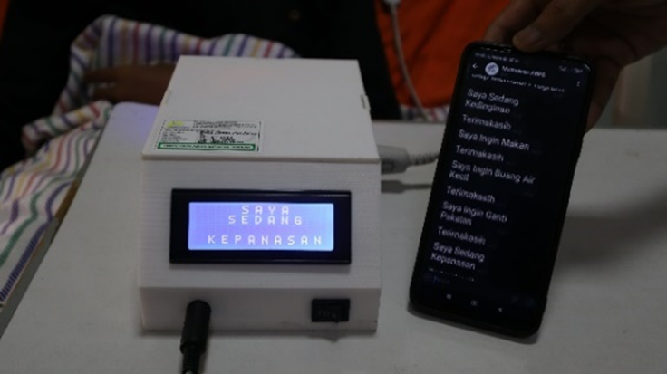
The results obtained after testing on respondent 10 indicate that the prototype functions well, can transmit communication phrases according to the Table 12 provisions, and achieves a sensor reading and interval accuracy of 100%. The components and circuitry of the prototype were optimized for functionality among the ten respondents. The prototype was functionally tested with 100% accuracy in reading all communication phrases, according to the working principle. It can read inputs from each touch on the touch sensor field, interpret interval times of phrases, and display sentences on a 20 × 4-character LCD and Telegram application. The results of phrase readings are shown in Fig. 9.
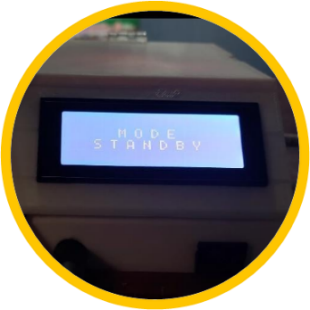
In this prototype, there is an additional mode, namely, the Standby Mode. The Standby Mode was activated when the device did not receive input data for selecting communication phrases for more than 1 minute. This mode anticipates errors in reading outputs when unintended touches or movements by the patient occur on the touch sensor. The display of the Standby Mode is shown in Fig. 10.
The Stroke Patient Communication Aid serves as a communication tool between the stroke patients and caregivers. The created prototype achieved a success accuracy of 100% for each communication phrase, whether displayed on the LCD or in the Telegram application. This prototype utilizes touch on the touch sensor area to select communication phrases displayed on the LCD, combined with a timer during the selection process. With a combination of two inputs, the prototype can generate communication phrases according to the patient's choices, displayed on the LCD and in the Telegram application as communication messages. When one of the inputs is not fulfilled, the device does not produce communication phrases on the LCD or in the Telegram application. The prototype boasts portability and rechargeability as its advantages. From a technological standpoint, this Stroke Patient Aid is based on IoT, where the desired communication from post-stroke patients will appear on the Telegram application using serial Wi-Fi communication. An additional feature of this Stroke Patient Aid is the standby mode, which prevents reading errors when a patient unintentionally touches the sensor area.
The author expresses gratitude to Muhammadiyah University of Yogyakarta, the parents, the academic advisor, the educators at the Medical Electro-Technology Laboratory of UMY, and the friends who supported the author in conducting this research.
Fajar Aji Pratama, Stroke Patient Communication Tool with Touch Sensor and Phrase Time Step