(1)
Journal of Fuzzy Systems and Control, Vol. 2, No 1, 2024 |
Application of LQG Control for Pendubot System
Duc-Anh-Quan Nguyen 1, Luu-Quang-Thinh Nguyen 2,*, Hoang-Anh Nguyen 3, Phu-Hung Nguyen 4, Quoc-Thai Tran 5,
Cao-Sang Pham 6, Hoang-Bao Tran 7, Van-Huy Pham 8, Anh-Quoc Nguyen 9, Phong-Luu Nguyen 10
1,2,3,4,5,6,7,8,9,10 Ho Chi Minh City University of Technology and Education (HCMUTE), Thu Duc city, HCMC, Vietnam
Email: 1 20151408@student.hcmute.edu.vn, 2 20151063@student.hcmute.edu.vn, 3 20151254@student.hcmute.edu.vn,
4 20145514@student.hcmute.edu.vn, 5 20145608@student.hcmute.edu.vn, 6 20145596@student.hcmute.edu.vn,
7 20151339@stundent.hcmute.edu.vn, 8 20145452@student.hcmute.edu.vn, 9 20145431@student.hcmute.edu.vn,
*Corresponding Author
Abstract —The paper focuses on the study of the Pendubot system, a classic system widely used in control research, particularly the 2-link Pendubot. This system is nonlinear with a single input and multiple outputs (SIMO) and is under-actuated. The paper addresses the challenges of applying optimal Linear Quadratic Regulator (LQR) control to Pendubot, requiring an accurate model without noise. The author proposes using a Kalman filter to estimate the system's state variables and mitigate the impact of noise. Subsequently, the LQR controller is applied based on the estimated state variables. Thus, the study suggests an integrated approach combining Kalman filtering and LQR control to enhance Pendubot's performance under real-world conditions. The combination of LQR and Kalman forms a new controller called LQG, which addresses issues encountered by standalone LQR and improves the system's optimal performance. The paper focuses on evaluating the performance of LQR and LQG controllers through system simulations with the input being the motor force applied to the first bar of the Pendubot system in MATLAB Simulink software.
Keywords—Pendubot, LQG Control, Kalman Filter, MATLAB/Simulink
Pendubot is an underactuated system with two degrees of freedom, as illustrated in Fig. 1, consisting of one actuated joint and two non-actuated joints [1]-[4]. In various experiments, researchers have analyzed the second-order mathematical equations of the Pendubot and employed control strategies for stability and trajectory tracking. Additionally, practical applications of Pendubot have been explored in control research and educational environments.
In these studies, the authors have modeled the system starting from a stable equilibrium position with a vertically downward configuration of the two joints to an unstable balanced position with the two joints in an upright configuration using a Swing-up control scheme [4]-[11]. Once the Pendubot is brought close to the balanced state, a balancing control law is activated to maintain the Pendubot in an upright position. Notably, solutions based on energy methods have been proposed. For instance, I. Fantoni and colleagues designed a control law by computing the potential energy of the pendulum at the upright position and establishing a Lyapunov-based control law [10]. In the study by Daniel J. Block [12], a linearization technique combined with a PD controller was employed to Swing-up the Pendubot to the unstable balanced position (Top or MID) by adjusting the parameters of KD and KP. An optimal control approach was also applied to achieve stabilization.
Over the past decades, several balancing control laws for Pendubot have been proposed to evaluate the system's stability [6]-[13]. These include nonlinear control laws, linear control laws, and intelligent control laws. However, the presence of noise in the system is a consideration in the development of control strategies in the field of control engineering. In a published paper in 2014, Nguyen Dinh implemented a nonlinear control law based on the Sliding Mode control technique for the underactuated system to achieve robust and stable control in a noisy environment [13]. In [14], a nonlinear disturbance observer was utilized to estimate and compensate for disturbances, enabling stable and balanced control for the Pendubot system. In [15], Adaptive sliding-mode neural network control is based on passive properties.
The Pendubot system is a complex nonlinear system, and computing its exact model can often be more challenging compared to a linear model. Hence, the authors propose the use of a Linear Quadratic Regulator (LQR) control law. However, due to the presence of noise in the system's operation, a Kalman filter is designed to estimate the system's noise. The combination of an LQR controller and a Kalman filter will result in an LQG controller. The control system's performance will be enhanced, and the LQG controller will mitigate the effects of system noise and measurement noise, which are the two primary causes of instability in the control system design. To design the LQR controller, linearization of the system around the operating point is required [4], [6]. Estimating the system's noise enables easier control of the system and reduces the energy supplied by the motor, thereby preventing potential damage.
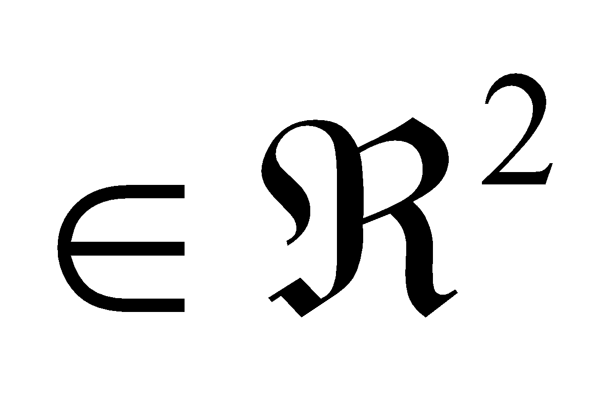
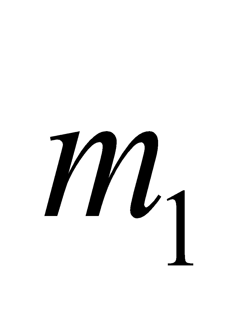
The Pendubot is a two-degree-of-freedom (two-DOF) underactuated system with two controlled joints, as depicted in Fig. 1. Joint one is directly linked and controlled (q1), while joint two is coupled to joint one through a connecting joint and equipped with an encoder to measure the angle (q2). The mass of joint one (two) is denoted as the length of link one (two) is defined as (l1(l2)), and the distance from the encoder axis to the center of mass of link one (two) is denoted as lc1(lc2). The inertia moment is located at the center of the mass of link one (two) and is defined as I1(I2). We apply the Euler-Lagrange equation as follows:
| (1) |
Where 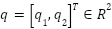 is the position vector and
  is the velocity vector of the system,
  is the input of the control variable. The obtained dynamic equation of the system is expressed as follows:
| (2) |
Where:





In addition,  is referred to as the inertia matrix,
  is referred to as the Coriolis matrix, and
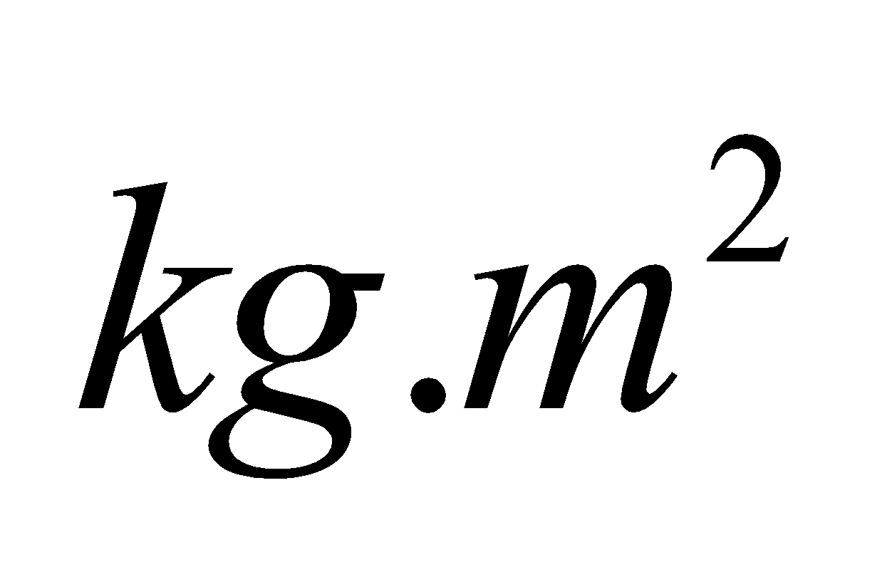
  is referred to as the gravity matrix. The parameters used in this paper are defined as presented in Table 1.
Before designing control and filtering systems for any given linear system, it is necessary to assess the controllability and observability of the system. Starting from the nonlinear equations, linearization around the operating point of the system is performed. In this case, the control is chosen at the TOP position as in Fig. 2.
Linear System:
| (3) |
When the system is stable, the state variables of the system will converge to zero:

The matrices A and B are obtained through linearization of the system around the operating point, resulting in:
 ;
;
The controllability matrix is given by:
| (4) |
Using the matrices A and B, we can assess the controllability of the system. If the rank of the controllability matrix, denoted as (4), is equal to the number of state variables, then we conclude that the system is controllable. Based on this, we can design a control system for the linearized system:
| (5) |
Therefore, based on the controllability matrix (5), we can conclude that the system is controllable.
Parameter | Description |
| Mass of link 1 () |
| Mass of link 2 () |
| Length of link 1 () |
| Length of link 2 () |
| Distance from the encoder axis to the center of mass of link 1 (m) |
| Distance from the encoder axis to the center of mass of link 2 (m) |
| Inertia moment of link 1 () |
| Inertia moment of link 2 () |
| Angle of link 1 with respect to the horizontal axis () |
| Angle of link 2 with respect to link 1 () |
The essence of the Kalman filter is an observer, and to construct this filter, it is necessary to assess the observability of the system. The observability matrix is presented:
| (6) |
The output-state matrix C of the system is as follows:

Therefore, we obtain the result:

Hence, based on the rank of the observability matrix being equal to the number of state variables, we can conclude that the system is observable.
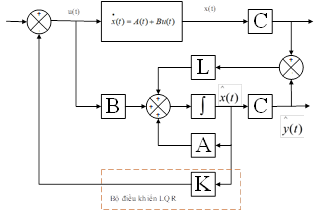
Fig. 3 illustrates the structure of the controller, and the LQG optimal control problem can be separately solved by addressing the pre-defined optimal control problem and the optimal state estimation problem. In this case, the state variables used for computation are denoted as  , with an additional component added as the estimation gain
  . The control signal
  is computed based on these state variables, resulting in a control signal with reduced amplitude oscillations, thereby minimizing adverse effects on the system.
The quality criteria can be expressed through the following fitness function:
| (7) |
The optimal control signal is designed as follows:
| (8) |
Where K is the state feedback gain matrix determined by the formula:
| (9) |
Where P is the positive semi-definite solution of the algebraic Riccati equation:
| (10) |
The authors simulated the discrete-time system using MATLAB software. To obtain the control gain, they utilized the dlqr (A, B, Q, R) function, which allowed them to calculate the coefficient K for the control design. Where Q and R are positive definite weighting matrices.
Consider a discrete-time linear system:
| (11) |
Where:  represents the system noise and
  represents the measurement noise.
Assuming that the system noise and measurement noise are non-Gaussian, uncorrelated, with zero mean and variances of:
| (12) |
| (13) |
The discrete Kalman filter has the following form:
| (14) |
Where L represents the Kalman filter gain, which is presented as:
| (15) |
With  being the solution of the Riccati equation:
| (16) |
To verify the operation of the controller presented in this paper, we will conduct a simulation using MATLAB/SIMULINK software. This simulation aims to examine the responses of the signals that need to be controlled by the LQG controller. Furthermore, we will compare the performance with the optimal LQR controller when the system is subjected to undesirable components such as measurement noise and system disturbances. In this simulation, we will control the Pendubot to balance in an upright position, facing upwards, with the state vectors . At this position, the controllability of the system has been verified using the formula (4). We will proceed with the simulation for a duration of 4 seconds, with a system sampling time of 0.01 seconds. During the simulation, we will compare the state variables of the system's output without a filter and the system's output with a filter to determine their advantages. The main parameters of the constructed system are presented in Table 2. Controller gain matrix K:

Observation matrix L parameters:

The system noise has very small parameters and is considered to be negligible:

The simulation control system is divided into several blocks as shown in Fig. 4:
Parameter | Unit |
=0.1 | (kg) |
=0.08 | (kg) |
=0.3 | (m) |
=0.4 | (m) |
=0.17 | (m) |
=0.21 | (m) |
=0.04 | () |
=0.06 | () |
=0.1 | (kg) |
=0.08 | (kg) |
Measurement noise is assumed: 
The assessment of the quality of the control and filtering on the Pendubot model presented:
In Fig. 5, the state variables' outputs are presented without the Kalman filter, while Fig. 6 illustrates the improved quality of the state variables' outputs with the application of the Kalman filter. It can be observed that the output quality of the Kalman filter is no longer affected by oscillations as seen in the absence of the filter, and the control quality is smoother. In Fig. 5, the angular velocity outputs of variables and exhibit strong oscillations, which negatively impact the system. However, with the application of the filter, the signals become flatter, and the oscillations disappear.
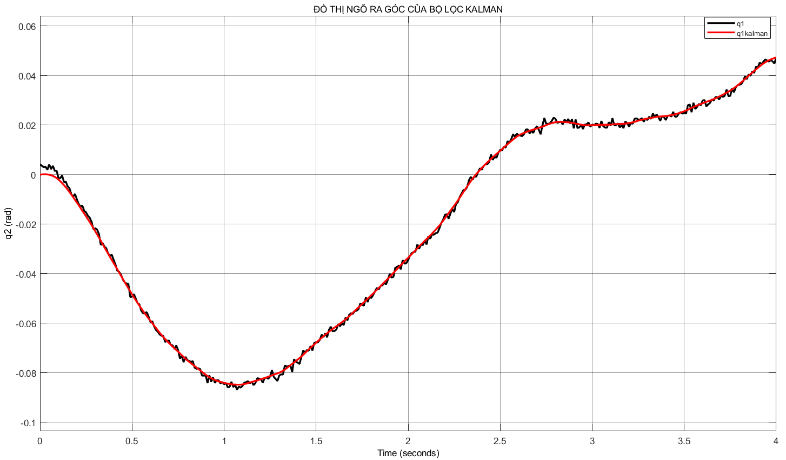
The angular outputs, affected by noise, are estimated remarkably well by the filter in Fig. 7 and Fig. 8. It can be observed that the continuous oscillations captured by the sensors are significantly reduced through the filter, resulting in flat and smooth signals. This indicates excellent performance of the filter.
The control signal supplied to the system from the motor is also crucial. In Fig. 9, when influenced by motor noise, the control signal exhibits significant oscillations. This can have a substantial impact and potentially damage the motor. However, with the implementation of the filter, the control signal operates with reduced oscillations, minimizing potential harm to the control system.
In this paper, the authors focus on developing a Kalman filter and combining it with an LQR controller to create an LQG controller for the Pendubot model. The goal is to minimize the influence of noise on the system and improve optimal control quality. Simulation results have shown that using the LQG controller significantly improves the system's response, enhances the quality of control signals, and increases the stability of the Pendubot. This research opens opportunities for further development in constructing parameter estimation sets to address unwanted influences on the system. The next development direction is to address noise-induced issues with systems of higher nonlinearity, such as arc robot systems.
Duc-Anh-Quan Nguyen, Application of LQG Control for Pendubot System