can be defined as.
Journal of Fuzzy Systems and Control, Vol. 2, No 2, 2024 |
Trajectory Tracking Control Design for Mobile Robot Using Interval Type-2 Fuzzy Logic
Mochammad Dekcy Akmal 1, Adnan Rafi Al Tahtawi 2,*, Kartono Wijayanto 3, Faisal Wahab 4
1, 2, 3 Department of Electrical Engineering, Politeknik Negeri Bandung, Bandung Barat, Indonesia
4 Department of Mechatronics Engineering, Universitas Katolik Parahyangan, Bandung, Indonesia
Email: 1 moch.dekcy.toi17@polban.ac.id, 2 adnan.raf@polban.ac.id, 3 karwij@gmail.com, 4 faisal.wahab@unpar.ac.id
*Corresponding Author
Abstract— A two-wheeled mobile robot (TWMR) is a type of mobile robot that is widely used for several tasks, one of which is trajectory tracking. This task will be complicated for the robot to track the desired trajectory when there are disturbances in the robot, such as the presence of noise from the sensor feedback. Therefore, a robust control mechanism is needed so that the robot is able to track the trajectory properly. This study proposes an Interval Type-2 Fuzzy Logic Control (IT2FLC) for controlling TWMR which has noise parameters in the heading angle. IT2FLC Sugeno method is designed with error input from the heading angel and its changes, while the output is a voltage for the left and right motors of the robot. The input membership function is constructed using a triangular function with three different Footprint of Uncertainty (FoU) values as a comparison. This controller is then implemented to control the heading angle according to the trajectory of the robot using the Differential Drive Wheeled Mobile Robot (DDWMR) kinematic model. Several scenarios are then testing via MATLAB/Simulink to see the controller performance. The test results by including the noise parameter as disturbance show that IT2FLC can produce a better performance when compared to ordinary FLC. The widest FoU value of 0.3 can produce the smallest error value of up to 0.003 on the ISE criteria.
Keywords— IT2FLC; DDWMR; Heading Angle; FoU; Disturbance
Nowadays, mobile robot technology is growing rapidly and has been widely applied in various fields. One type of mobile robot that is widely used is the Differential Drive Wheeled Mobile Robot (DDWMR). This robot moves based on the difference in the rotational speed of the wheels which are controlled separately. Both wheels are driven by an electric motor with a separate voltage source. This difference will result in the resultant direction of the robot's movement and the linear speed of the robot in carrying out its mission. Generally, DDWMR has two main wheels, each of which is driven by a separate drive and is equipped with a castor wheel that is placed in front or behind the robot as a counterweight. DDWMR can be modeled using kinematics and dynamics models. Kinematics models are often used because they have simpler equations when compared to the dynamic model. Besides, mobile robots usually use only the low speed of the motor to control the loop.
One of the most widely applied tasks in DDWMR is trajectory tracking. The robot must follow the desired trajectory with minimal error. Various control methods can be used in this task, such as Lyapunov-based control [1], back-stepping control [2], sliding mode control (SMC) [3], [4], fuzzy logic control (FLC) [5]–[8], and model predictive control (MPC) [9]–[11]. These methods can be applied to both kinematic and dynamic models of the robot, and are usually performed to reject disturbance. The presence of disturbances in the robot such as that caused by measurement noise can reduce control performance. Thus, a robust control scheme is needed that can overcome disturbances to the robot. Several previous studies have designed robust control schemes for mobile robots. Research [12] and [13] designed an SMC for a DDWMR tracking system with various disturbances such as measurement noise parameters, frictional disturbances, and model uncertainty. The simulation results show that the proposed controller can produce good transient and steady-state responses when there are any disturbances. Then, research [14] designed an MPC on a mobile robot to reject disturbance. Two observers are designed to estimate the disturbance signal. The combination of the observer and SMC produces an asymptotically stable system if the harmonic frequency of the disturbance is known. A robust control approach with intelligent systems based on the neural network has also been carried out by [15]. The adaptive neural network tracking controller has been designed to estimate disturbances in a mobile robot. Then the intelligent system approach based on Z-number FLC has also been investigated by [16] to produce a robust tracking control. Lastly, robust control of mobile robots using a particle swarm optimization (PSO) algorithm approach has also been investigated by [17] for obstacle avoidance missions. Based on some of the studies above, the intelligent systems approach in the controller design is considered simpler when compared to the mathematical model approach because it does not involve a mathematical model equation of the plant to be controlled.
FLC is one of the intelligent control methods that are often used because of its simplicity in terms of design and implementation. In addition, FLC can be used as the basis for intelligent control by applying other artificial intelligence algorithms such as ant colony and PSO in the optimization process [18]. Currently, the Interval Type-2 Fuzzy Logic Controller (IT2FLC) is present as the development of the ordinary FLC. IT2FLC can produce robust control performance because it has a Footprint of Uncertainty (FoU) in its input membership function [19]. FoU is a range of values found at the foot of the linguistic set so that it is considered capable of overcoming the uncertainty of values that occur in the fuzzy membership function. This is proven in several applications, especially in the case of trajectory tracking control on mobile robots. Research [20] designed IT2FLC to control mobile robot navigation with wheel slip and uncertainty parameters. The results of simulation and validation using the VREP simulator show that IT2FLC produces better performance when compared to ordinary FLC in overcoming parameter uncertainty. A dynamic-group particle swarm optimization (DGPSO) algorithm is proposed by [21] to provide navigation control and obstacle avoidance for a mobile robot. The results show that the proposed method is more efficient than other optimization methods in an unknown environment. IT2FLC has also been combined with SMC with a double-loop mechanism for trajectory tracking of the mobile robot [22]. IT2FLC is used to adjust the switching gain of the SMC when a disturbance occurs. The simulation results show that the proposed method produces good performance in terms of small errors and fast-tracking. In the intelligent systems approach, IT2FLC can also be integrated with a neural network in terms of parameter learning when the mobile robot is faced with a trajectory-tracking task [23]. Based on several studies related to the application of IT2FLC on mobile robots above, it can be concluded that IT2FLC can produce robust control performance when there is a disturbance on the robot. However, from these studies, the effect of FoU width on the IT2FLC input membership function on control performance was not investigated. Based on research [24], wider FoU will improve control performance on DC motor plant and water level tanks.
Based on previous research, IT2FLC can be applied for mobile robot control in terms of trajectory tracking [20]- [23]. Thus, this study aims to design a trajectory-tracking controller on a Two-Wheeled Mobile Robot (TWMR) using IT2FLC with various FoU values. IT2FLC is designed to overcome the presence of measurement noise parameters on the robot’s heading angle with input in the form of heading angle error and its changes. The resulting control signal is a voltage for each motor of the robot. The control performance generated by IT2FLC is then compared with ordinary FLC and also performed with various FoU values. To test the proposed controller, a DDWMR kinematics model was built using MATLAB/Simulink for simplicity. The main contribution of this paper is to produce a robust mobile robot trajectory tracking performance and to see the effect of the various intervals of the FoU values on the designed controller. As a preliminary study, we use the IT2FLC Toolbox developed by [25] with the Karnik-Mendel (KM) type reducer method. This is due to the ease of design and simulation.
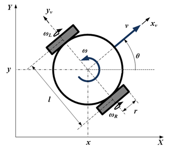
The TWMR can be modeled using the DDWMR model. A top view of the DDWMR geometry model used in this study is depicted in Fig. 1. The robot model consists of two coordinate frames, namely the reference frame and the vehicle frame. The reference frame can be defined as.
| (1) |
while the vehicle frame  as.
as.
| (2) |
The transformation of the robot coordinates from the vehicle frame to the reference frame satisfies the following equation.
| (3) |
In the DDWMR model, several constraints must be met or are usually called non-holonomic constraints. These limitations are:
 . Based on the inverse transformation matrix of
  , it is obtained that
| (4) |
| (5) |
| (6) |
Equation (4) to equation (6) can be formed as
| (7) |
| (8) |
where A(P) is a non-holonomic constraint matrix. The DDWMR model can be formed using a kinematics approach. The kinematics model that is usually used in mobile robots is forward kinematics. This model aims to obtain the linear speed  and angular speed
  of the robot if the speed of the right
  and left wheels
  are known.
The model can be formed as.
| (9) |
If the model is transformed in the reference frame, it can be written.
| (10) |
If equation (9) is substituted into equation (10), it can be formed.
| (11) |
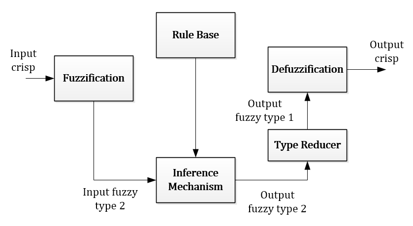
The block diagram of IT2FLC is shown in Fig. 2. In general, the IT2FLC block diagram is almost the same as the type 1 fuzzy logic controller, which consists of the fuzzification process, inference mechanism, and defuzzification. The difference lies in the type reduction process, wherein in this process the output value of the inference mechanism is reduced so that the defuzzification process can be carried out.
As in ordinary FLC, the output of IT2FLC can be calculated in the following steps:
 rules as follows
| (12) |
where  is the antecedent and
  is the consequent membership function.
 , compute the membership degree of fuzzy sets for each
  and each or can be written
  for
for  and
and  .
.  for where
| (13) |
| (14) |
 and the corresponding rule consequent using Type Reducer (TR). The TR commonly uses the center-of-sets which defined as
| (15) |
where
| (16) |
|
 and
and  are switching points that can be found using several iterative algorithms.
| (18) |
The crisp output value  is an IT2FLC control signal that will be used to control the plant.
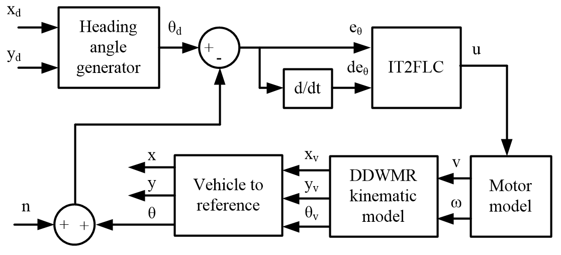
In this section, IT2FLC will be designed to control the movement of the robot while tracking the trajectory. This study assumes the presence of noise in the sensor that detects the trajectory so that it affects the control performance. The proposed control scheme can be seen in Fig. 3.
Given the desired robot posture  as reference trajectory, thus the desired heading angle
  can be calculated as follows
| (19) |
where
| (20) |
| (21) |
The resulting heading angle is then used as a controlled variable. We do not use trajectory coordinates  as a control setpoint because it will be more complex in FLC design as well as rule-based design. In this study, the controller is designed with the input error of the heading angle
  and its changes
  which are defined as follows
| (22) |
| (23) |
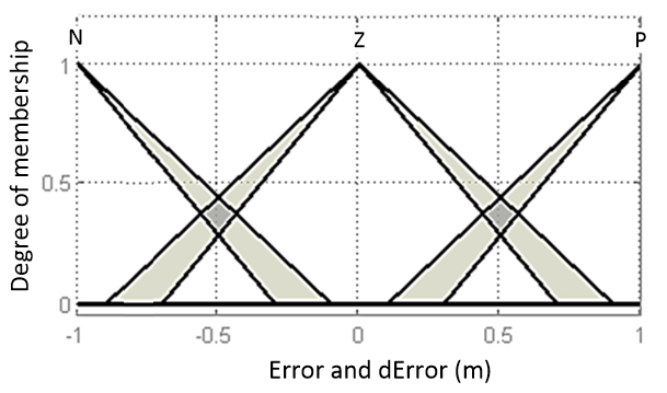
with the membership function depicted in Fig. 4.
We use the same membership function for both input variables. As can be seen, the difference between IT2FLC and ordinary FLC is the presence of FoU in the input membership function. In this design, the two input variables are formed using three triangular linguistic sets, namely Negative (N), Zero (Z), and Positive (P) which have a width of FoU 0.2 with a range of values shown in Table 1.
Sets | Values |
N | Upper = [-1 -1 -0.1 1] Lower = [-1 -1 -0.3 1] |
Z | Upper = [-0.9 0 0.9 1] Lower = [-0.7 0 0.7 1] |
P | Upper = [0.1 1 1 1] Lower = [0.3 1 1 1] |
The output of the controller is the voltage for both motors of the robot that is classified into seven crisp values Negative High (-12), Negative Medium (-8), Negative Low (-4), Zero (0), Positive Low (4), Positive Medium (8), and Positive High (12). Then the rule-base is defined as shown in Table 2.
E/dE | N | Z | P |
N | NH | NM | NL |
Z | NM | Z | PM |
P | PL | PM | PH |
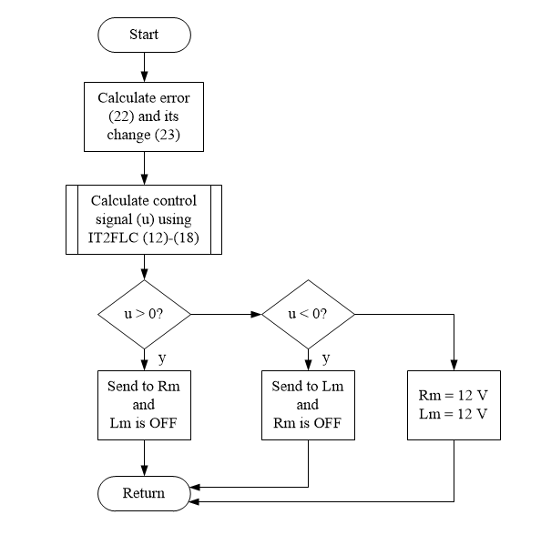
The calculated control signal according to equations (12) to (18) is then given to the right motor (Rm) and the left motor (Lm) based on the algorithm as shown in Fig. 5. We use a DC motor model as an actuator that receives control signals [26]-[28]. These two DC motors will then move the mobile robot towards the desired trajectory.
The control signal given to the motor will then cause the robot's translation speed and motor rotation speed. These two quantities then become input for the kinematic model in equation (10). Then, using the vehicle to reference the transformation matrix, heading angle data will be obtained which will be used as feedback.
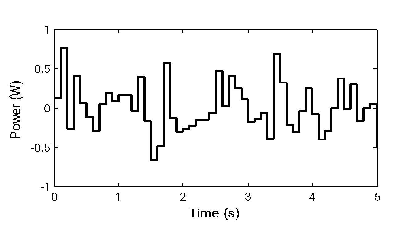
In this section, the proposed controller will be tested to see the robot’s response when moving on the desired trajectory. The robot model was built based on Fig. 3 using MATLAB/Simulink. The test is carried out by providing a disturbance signal as shown in Fig. 6 with a power parameter of 0.1 W and a frequency of 100 Hz. This disturbance signal represents noise in the detection of the robot heading angle sensor.
Three trajectory scenarios namely straight, curved, and sinusoidal are used in this test. In each test, the response of the head angle to the reference, the position of the robot in the reference frame, the translational speed, and the rotational speed of the robot will be seen and analyzed. Then the response to the control of the heading angle was compared to ordinary FLC. The error is then analyzed using the integral error method, namely Integral Absolute Error (IAE), Integral Time Absolute Error (IAE), Integral Square Error (ISE), and Integral Time Absolute Error (ITSE) using the following equations.
| (24) |
| (25) |
| (26) |
| (27) |
Finally, the effect of the various FoU values on the input membership function on control performance will also be investigated. For simulation requirements, the parameters used for the DDWMR model including the motor model are presented in Table 3. We use IT2FLC MATLAB Toolbox for designing the controller developed by [25] for simplicity. The controller is then implemented on the DDWMR model using MATLAB/Simulink.
Parameters | Values |
Distance between the drive wheel and the axis of symmetry (l) | 5.6 m |
Wheel radius (r) | 0.2 m |
Motor resistance (R) | 5 Ohm |
Inductance (L) | 0.0054 H |
Moment of inertia (J) | 0.00015 Kg.m2 |
Rotor friction (b) | 0.0001 N.m.s |
Motor constant (K) | 0.1 |
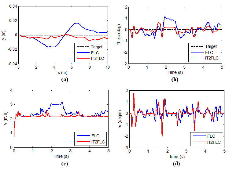
The first test is carried out on a straight line or  and
and  . Thus, according to equation (19)
  is obtained. The test results can be seen in Fig. 7.
Based on the test results, it appears that IT2FLC produces better performance than FLC. Fig. 7(a) shows the movement of the robot when it is on a straight trajectory where IT2FLC produces a smaller deviation than ordinary FLC. Fig. 7(b) is the resulting robot heading angle where the deviation from IT2FLC is also smaller when compared to FLC. Fig. 7(c) is the translational speed of the robot. It can be seen that IT2FLC produces robot speed with smaller oscillation than FLC. Fig. 7(d) shows the rotational speed of the robot when moving on a trajectory where IT2FLC produces an oscillation frequency lower than FLC.
The second test is done using a curved trajectory. The desired trajectory is described as and  with resulted heading angel
  . The test result for this trajectory is depicted in Fig. 8.
In the second scenario testing, IT2FLC also produces better control performance than ordinary FLC. Fig. 8(a) shows the movement of the robot where IT2FLC produces a smaller deviation than ordinary FLC when the system is disturbed. Fig. 8(b) shows the resulting robot heading angle on the second scenario testing. Fig. 8(c) shows the translational speed of the robot where IT2FLC produces robot speed with smaller oscillation. Fig. 8(d) shows the rotational speed of the robot where IT2FLC produces a lower oscillation frequency in the last simulation time.
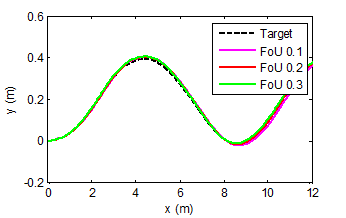
The last testing is carried out using a sinusoidal trajectory. The desired trajectory is generated as and  with heading angel
  . The test result is depicted in Fig. 9. The last scenario testing result shows that IT2FLC also produces better control performance. Fig. 9(a) shows the movement of the robot on the reference frame, where IT2FLC produces a smaller deviation significantly. Fig. 9(b) shows the comparison of the robot heading angle between FLC and IT2FLC. Fig. 9(c) is the translational speed of the robot where IT2FLC gives the best response if compared with FLC. Fig. 9(d) is the rotational speed of the robot where IT2FLC also gives the smallest oscillation.
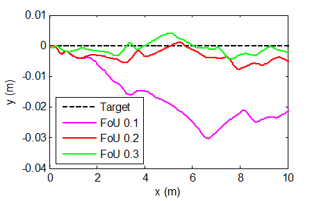
In the last section, a test was conducted on IT2FLC with different FoU. The test aims to see the effect of the FoU width on the input membership function on control performance. The test is carried out by changing the value of FoU 0.2 to be smaller (0.1) and larger (0.3) with a range of values for each FoU can be seen in Table 4. Then, the response of the robot’s movement and the heading angle of the robot are observed and the error values are compared for each FoU.
Sets | FoU = 0.1 | FoU = 0.3 |
N | Upper = [-1 -1 -0.15 1] Lower = [-1 -1 -0.25 1] | Upper = [-1 -1 -0.05 1] Lower = [-1 -1 -0.35 1] |
Z | Upper = [-0.85 0 0.85 1] Lower = [-0.75 0 0.75 1] | Upper = [-0.95 0 0.95 1] Lower = [-0.65 0 0.65 1] |
P | Upper = [0.15 1 1 1] Lower = [0.25 1 1 1] | Upper = [0.05 1 1 1] Lower = [0.35 1 1 1] |
The test result of the robot's movement and its heading angle for three scenarios testing with different FoU is shown in Fig. 10. Based on the test results, it can be seen that FoU = 0.3 produces better control performance than FoU = 0.2 and FoU = 0.1. This can be seen from the smaller robot deviation at FoU = 0.3 when given a disturbance.
(a) | (b) |
(c) | |
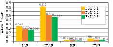
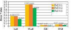
To prove it, the error integral calculation is repeated in all test scenarios. The results are shown in Fig. 11. The result of the comparison of integral error with different FoU for each trajectory scenario shows that the wider the FoU, the better the robustness of the response. This means that the FoU on IT2FLC represents a range of uncertainty, one of which is caused by measurement noise. However, this result cannot be proven mathematically. In addition, the reliability of the computing device needs to be considered since IT2FLC has a wide FoU, and iterations on the type reduction algorithm are quite complex.
(a) |
(b) |
(c) |
Trajectory tracking control for the TWMR kinematics model using IT2FLC has been successfully designed and tested. Three different FoU values were tested in three robotic trajectory scenarios. The results show that IT2FLC has better robustness when compared to ordinary FLC when the robot is given noise parameters. Furthermore, the larger the FoU width on IT2FLC results in better control performance where the resulting integral error is smaller. In further research, optimization of FoU selection can be applied so that a response that is considered optimal can be produced.
Mochammad Dekcy Akmal, Trajectory Tracking Control Design for Mobile Robot Using Interval Type-2 Fuzzy Logic