Journal of Fuzzy Systems and Control, Vol. 2, No 2, 2024 |
Wind Power Generation for Isolated Loads with IoT-based Smart Load Controller
Arunava Chatterjee
Department of Electrical Engineering, Raghunathpur Government Polytechnic, Purulia, W.B., India
Email: arunava7.ju@gmail.com
Abstract— This study presents an investigation of combining a microgrid structure for the generation of power with a wind energy conversion system. The chief purpose of the study is to provide a smart controller for such a hybrid system with a dump load for controlling the generated voltage. The smart load controller is used which is unique and it is controlled using Internet-of-Things (IoT) for easier and flexible control. Only the dump load is controlled using the IoT-based controller in a way to keeps the bus voltage at a steady value. With the proposed control, the load voltage regulation becomes better with reduced transients. The generation system can be modeled and installed in any isolated place with optimized use of renewable sources with stable power output. Simulations and experimental observations on a laboratory setup for load control authenticate the proposed method.
Keywords—Dump Load; Induction Generator; Internet-of-Things; Smart Load Controller; Wind
The bulk of the energy essential to create electricity comes from using fossil fuels viz., oil, coal, and natural gas. Combustion of fossil fuels releases a large amount of toxic gases into the environment. Besides, their supply is also limited in nature. As a result, the demand for sustainable, clean energy sources never goes away. Wind is one such clean, limitless renewable energy source [1]. Wind turbines coupled to generators are by far the most often used device for the conversion of wind energy to electricity. It is theoretically possible to place a wind turbine coupled to a generator to generate power. Grid-compatible electric power may still be necessary even if the generator simply generates variable amplitude and frequency direct current or alternating current. Fortunately, this need may presently be met by connecting proper converters.
The induction generator (IG) is a good candidate for many electrical generations from renewable sources because of its dependability, low upkeep requirement, and control ease [2]. Because of their resilience, convenience of use, and small size per kilowatt generated, IGs are endorsed for the generation of electricity from wind. Furthermore, even in the absence of an external grid source, IGs have the potential to generate an excitation magnetic field using static capacitors. As such, they can be applied in grid-secluded areas [3]–[5]. With the advent of power converters, which make it easier to supervise the voltage output of IGs, the primary drawbacks of IGs remain to be reactive power requirement and inferior voltage regulation at changing speeds and loads [6][7].
Because it does not require a separate source of power for magnetic field generation, for wind-harnessed electric generation, the self-excited induction generator (SEIG) is a good choice. SEIG is a particularly better performer in places with varying wind speeds and in seclusion. The SEIG arrangement was considered more than eighty years ago, however, in recent years, a lot of research has focused further on the study and applications of SEIGs [8]–[11]. It is because over the past thirty years, breakthroughs in voltage and frequency control techniques have been made, and there is now a global emphasis on developing and modifying renewable energy sources [12]-[16].
The chief functioning problem with the SEIG for wind generation is its incapability to regulate voltage and frequency at different operation conditions. An alteration in the load has an immediate consequence on the machine excitation. The excitation capacitors' reactive power is shared by the load and the induction generator. As a result, inadequate voltage control results in the voltage dropping at generator terminals as the load is increased. In contrast, even when the prime mover's speed remains constant, the induction generator's slip increases with increasing load, producing a frequency that is dependent on the load. Thus, along with wind energy, often photovoltaic (PV) panels are used as a hybrid source as both sources complement each other in diverse weather situations [17]-[20].
Isolated loads are frequently supplied by renewable energy from hybrid sources of production [21][22]. For independent or secluded generations, different sources such as wind-PV [23] and hydro-PV [24] are employed to provide distant and grid-inaccessible loads. They do, however, raise the upfront and ongoing operating costs of the system. Therefore, in addition to technical research, an economic study is equally crucial. Control strategies founded on maximum power point tracking (MPPT) are frequently used for both wind and PV. Grid-connected generation can be more easily controlled using MPPT technologies [25]. Isolated generation is often done without MPPT to minimize system cost and intricacy. However, sustaining a steady generation becomes critical since separate generations are often used to supply critical loads [26]. Due to the IG’s significant dynamic slip variations and the encounters of making a smooth adjustable reactive power source at a cheap rate, the control of speed and voltage does not often produce a proper generation output. Electronic load controllers (ELC) are also quite common nowadays which helps to maintain the generated power at a constant value from a SEIG. To maintain the stability of electricity generated by a SEIG on the demand side, an ELC redirects excess power to a dump load or storage [27]. The ELC is a tested approach for load control however, these controllers are not always flexible in operation and have problems with the requirement of extra hardware.
The proposed study mainly focuses on providing a solution to these problems for supplying isolated and critical loads. In this study, a smart load controller is used for maintaining the generated voltage from the IG. Previously, smart ELC-based dump load control was not attempted, and this adds to the control flexibility and better regulation of voltage than simple ELC. The main idea behind the use of a dump load with a load controller is to consume the balance power output. The balanced power output is the difference between the generated power from the induction generator and the actual consumed load power. This will maintain the generated power at a constant level. A smart, IoT-based load control strategy makes easier and more flexible control of the dump load. Such IoT-based control is also used for controlling different loads remotely allowing flexible and quicker load management [28][29]. The system cost is marginally increased with automated load management and control advantages. The proposed system is described in Section 2 along with the technical details and software-based cost assessment. Section 3 describes the smart control of the dump load. The results are shown in Section 4. Finally, the conclusions are provided in Section 5.
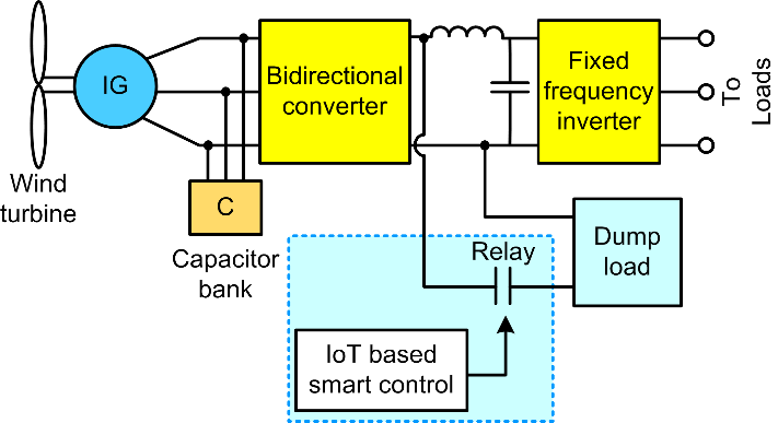
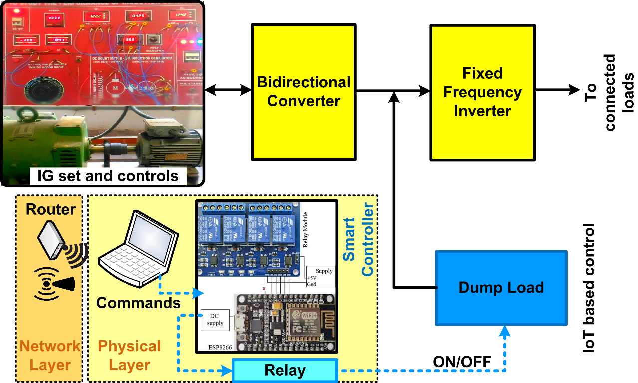
In the proposed generating system, a wind turbine is coupled to a three-phase induction machine for wind-power generation. For supplying the initial reactive power, the stator windings of the induction machine are linked to a capacitor bank. Balancing reactive power is employed to calculate the preliminary excitation [2]. To enhance and assist generation, the IG can also be connected to a backup photovoltaic panel with an associated storage unit. The loads on the system are also connected to a smart dump load. As mentioned, the isolated IGs frequently suffer from delinquent voltage regulation. The dump load can be used in such cases to provide proper voltage regulation of the IG. The load is controlled using an Internet-of-things (IoT)-based controller. Fig. 1 shows the block diagram of the entire scheme.
The proposed scheme has a dump load setup connected to the DC bus. The dump load controller works on the basis of consuming the difference between the linked consumer load's power consumption and the generator's constant output power. The generated power from the IG is maintained at a constant value and is taken as the summation of the load power and the power expended in the dump load. This dump load is connected to the DC bus and has another advantage of taking fewer components for connection and easier and more flexible control using the smart IoT-based controller. The consumer loads are connected to an inverter operated at a fixed frequency. The inverter is operated at a frequency of 50Hz to supply consumer loads.
The IoT-based smart load controller is realized using an ESP8266-based controller. The controller is powered using an external supply. The dump load is connected to the DC bus via a relay-based electronic switch. The switch is operated using the IoT-based controller. The IoT controller is operated using a closed-loop voltage control scheme. Here, the bus voltage is detected and equated with a reference voltage. The bus voltage error is sensed, and this signal is used to operate the smart controller for operating the dump load. In order to offset any decrease in consumer power, the generator's power output is maintained constant by raising the dump load power.
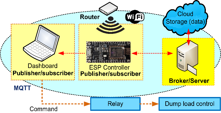
The IoT-based controller is controlled using a visual dashboard from a laptop computer. However, the same can also be controlled using an Android mobile. The IoT-based controller uses communication with servers as regards the condition of the bus voltage and current. This communication is maintained using the popular Message Queuing Telemetry Transport (MQTT) protocol [30]. MQTT is a machine-to-machine (M2M) network protocol that is lightweight and uses a publish-subscribe model for message queuing [31]. Fig.2 shows the MQTT protocol representation.
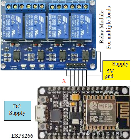
Because the relay coil is connected to switch loads, the circuit performs better under a range of loading and wind speed situations. The controller uses an ESP8266 Wi-Fi enabled board which is also capable of controlling the loads remotely. The dump load can be turned ON or OFF remotely using the controller allowing flexible control. The controller is also suitable for multiple load control. For the same, a relay module may be used instead of a single relay for control of a single dump load. The smart load controller then can be used to control several loads ON or OFF depending on the requirement and load power available. The ESP controller configuration along with a relay module is shown in Fig. 3. The physical layer of the IoT is made up of hardware elements such as relay switches, loads, voltage and current sensors, etc., while the network layer is made up of routers and other signals. The IoT smart control structure, which is utilized for load control, includes both of these levels and thus it can be thought of as a hierarchical structure-based control.
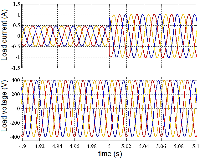
The IG is simulated using the MATLAB/Simulink-based model. The 3-phase IG used for the simulation is rated at 2kW, 415V, 50Hz, and 4-poles. A similar rated machine is used for experimental setup. For simulation purposes, a wind turbine is connected to the IG shaft for power generation. The setup also uses excitation capacitors of 36μF, and 400V, and are connected in star configuration in the stator windings. A DC motor prime mover driven at a closed loop that mimics the features of a wind turbine powers the IG system. A speed controller that receives data from wind turbines helps with this. Using closed-loop control, the controller modifies the speed based on the speed of the shaft. Both the fixed frequency inverter and bidirectional converter are designed with K2611 MOSFETS rated at 900V, 11A. An LV-25-P voltage sensor detects the voltage of the DC bus. Using the simulation setup, at first, the load voltage variation as obtained with a change in load current from half-rated to rated load is obtained at rated speed as shown in Fig. 4.
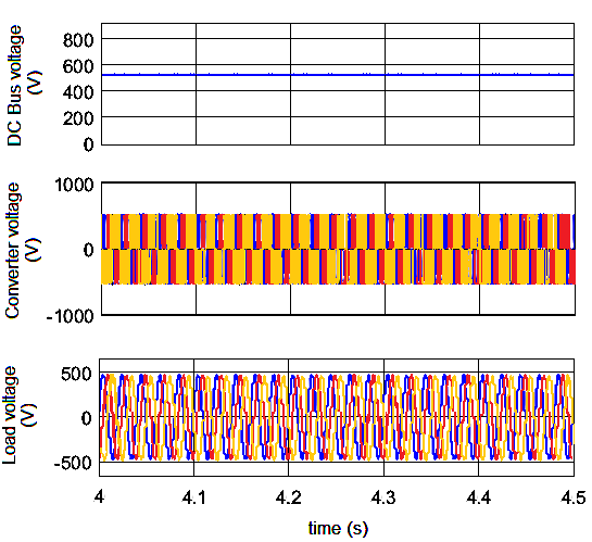
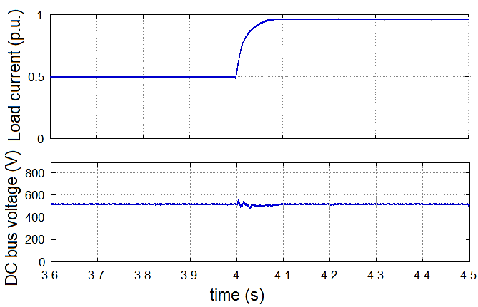
The load voltage is sustained at a fairly constant value as seen from the figure using the proposed control. The DC bus voltage, bidirectional converter voltage, and load voltage during steady state are shown next in Fig. 5. As perceived from the simulation, the voltages are maintained at stable values. Next, the voltage of DC bus variation with a step alteration in load from 0.5 p.u. to rated load is depicted in Fig. 6. It is observed that the DC bus voltage becomes steady within a few milliseconds using the proposed smart dump load control. The transient time is minimal.
The experimental setup is shown in Fig. 7. As already mentioned, the hierarchical layer is used for the MQTT protocol. This protocol is used for communication between the controller and the load. Both these layers are part of the IoT smart control structure that is used for dump load control. The different loads can be controlled using a visual controller dashboard which can be installed in a laptop computer or in an Android mobile.
The fixed frequency inverter is run at a fixed frequency of 50Hz using an Atmega microcontroller for supplying different consumer loads. This will allow the consumer loads to be always operated at the rated supply frequency of 50Hz. The three-phase induction machine parameters are provided in Table 1.
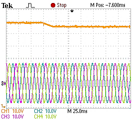
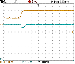
Additionally, other sources of renewable energy for instance solar-photovoltaic sources can be added to the DC bus for increased reliability of the generation system. This will also aid the system in supplying grid-isolated critical consumer or commercial loads. The load voltage waveform from the experimental laboratory setup obtained is shown in Fig. 8. From the figure, it is observed that with the reduction in speed of about 200 rpm, the load voltage remains steady with the planned control. The operation of the IoT-based smart dump load controller with a change in load is shown in Fig. 9. The DC bus voltage condition is also shown. It is observed that with a step increase in load from half-rated to rated load, the DC bus voltage is decreasing which is set stable after the dump load is turned ON. The voltage transients are also quite minimal and typically die within a few milliseconds. This is also an advantage of the proposed control. Although separate control schemes are available to reduce these transients [9], the proposed scheme is less complex and thus simpler for IG control with better load transient response. The load is thus sustained with an increase in load current as the voltage is kept at a steady value using the planned control.
Parameters | Values/phase |
Stator circuit resistance | 6.44 Ω |
Rotor circuit resistance | 6.57 Ω |
Stator and rotor leakage inductance | 8.55mH |
Magnetising inductance | 276.55mH |
Inertia constant | 0.142kg.m2 |
This paper offers a three-phase wind generation scheme with a smart IoT-based dump load controller for controlling and keeping the generated power steady. As observed from the control, the generated power is kept at a constant value with changing loads. With the smart IoT-based dump load controller, the control strategy is flexible and requires fewer connecting components than a regular electronic load controller. The control can be realized from an isolated setting also and thus it is suitable even for grid-connected applications. In future studies, the control may be applied for grid-connected applications and for supplying critical loads that require stable input voltage. Furthermore, testing of the smart load controller will be done with different wind speeds and load situations in the future.
Arunava Chatterjee, Wind Power Generation for Isolated Loads with IoT-based Smart Load Controller