Journal of Fuzzy Systems and Control, Vol. 2, No 3, 2024 |
|
Experiment Ball Levitation with Fuzzy PID and PID Implementation
Hoang-Thuat Nguyen 1,*, Anh-Quan Dao 2, Van-Phu-Quy Hoang 3, Quyen-Anh Nguyen 4, Truong-Phu Dang 5,
Minh-Nam Tang 6, Vu-Huy Le 7, The-Nam-Vuong Bui 8, Tien-Dung Nguyen 9, Thi-Hong-Lam Le 10
1 Bosch Vietnam, Dong Nai Province, Vietnam
1, 2, 3, 4, 5, 6, 7, 8, 9, 10 Ho Chi Minh City University of Technology and Education (HCMUTE), Vietnam
Email: 1 fixed-term.thuat.nguyenhoang@vn.bosch.com, 2 18151108@student.hcmute.edu.vn,
3 20151409@student.hcmute.edu.vn, 4 20151332@student.hcmute.edu.vn, 5 20151310@student.hcmute.edu.vn,
6 20151304@student.hcmute.edu.vn, 7 20142337@student.hcmute.edu.vn, 8 20151110@student.hcmute.edu.vn,
9 20151343@student.hcmute.edu.vn, 10 lamlth@hcmute.edu.vn
*Corresponding Author
Abstract—The “Ball Levitation” experiment can be easily recognized, like iFly in Singapore, and is greatly integrated into industrial fields such as flow control systems, aerodynamic testing, the oil and gas industry, HVAC systems, etc. Therefore, it is utilized in university laboratories for student exploration of non-linear control technology. The main objective of this experiment is through the position of the ball which is measured by an ultrasonic sensor to execute the PWM of the blower fan in order to control the speed of one so that the ball can be stabilized consistently at a specific height. Despite its uncomplicated model, the challenge of this model is from non-linear effects on the ball and the intricate physics governing its movement. Moreover, the ball is highly responsive to external influences from the blower fan. Consequently, conventional mathematical control methods struggle to handle it, making the simulation and comparison of control algorithms challenging. A Fuzzy-PID controller is meticulously designed to automatically stabilize the ball's position by considering the PID parameters with pre-defined fuzzy rules due to the actual showcase of the model. This setup allows us to experimentally compare the traditional PID controller with the Fuzzy-PID controller. The results reveal notable differences in the performance characteristics of these controllers.
Keywords—Ball Levitation; Fuzzy PID; PID; Genetic Algorithm; Non-linear
Introduction
The "Ball Levitation" experiment, akin to iFly in Singapore, has emerged as a hallmark for both academic exploration and industrial innovation. Initially conceived for student engagement and research in nonlinear control technology within university laboratories, its potential impact extends far beyond academia [1]-[3]. This experiment, with its ingenious simplicity, offers profound insights into the complexities of nonlinear systems and their applications across various industrial domains.
The experiment mainly focuses on comparing two controllers to evaluate their effectiveness [4]-[6]. At its core, the experiment revolves around the precise control of a levitating ball's position using ultrasonic sensors and PWM-controlled blower fans [7]. The overarching goal is to stabilize the ball at a specific height by dynamically adjusting the fan speed. However, beneath this seemingly straightforward objective lies a multitude of challenges stemming from the nonlinear dynamics governing the ball's behavior and its susceptibility to external influences from the blower fan.
When the ball is positioned at the top of the tube and the voltage is slowly decreased, it can be moved to a midpoint within the tube. At this stage, the ball's behavior becomes erratic, exhibiting instances of wobbling, floating, and spinning along both vertical and horizontal axes. The rotational movement of the ball is attributed to the principles of Bernoulli and the Coanda effect. Traditional mathematical control methods often fall short of adequately addressing these challenges, underscoring the need for more advanced control strategies.
PID method [8] is a classical linear method that was applied well to this model [9][10]. And, the fuzzy method is a classical intelligent method that was applied successfully to this model [11][12]. In response, the integration of Fuzzy-PID [1][7][13] Controllers have emerged as a promising solution. By leveraging fuzzy logic to tailor PID parameters [9][14] Based on predefined rules derived from actual model behavior, Fuzzy-PID controllers offer enhanced stability and performance in controlling the levitating ball. This paper presents a comprehensive exploration of the integration of the "Ball Levitation" experiment into various industrial fields, including Flow Control Systems, Aerodynamic Testing, the Oil and Gas Industry, and HVAC Systems, among others. Through experimental comparisons between traditional PID controllers and Fuzzy-PID controllers [5][15], we elucidate the remarkable differences in their performance characteristics, highlighting the transformative potential of advanced control technologies in industrial applications.
By bridging the gap between academic research and industrial practice, this study not only advances our understanding of nonlinear control technology but also paves the way for its widespread adoption and integration into real-world industrial processes.
RESEARCH METHOD
Mathematical Model of BBRW
The dynamic equation for an air levitation system (Fig. 1) is derived from Newton's second law of motion. Previous research [1] has extensively examined aerodynamic lift. The air levitation system comprises a ping-pong ball with mass , positioned beneath a fan at a distance
  within a plexiglass enclosure. The fan, when supplied with current, generates airflow to attract the ball. The resultant force, balancing the airflow force and gravitational force, induces upward or downward motion of the ball. An ultrasonic sensor measures the distance between the pipe bottom and the ball, providing positional information.

- Scheme of air levitation physical forces
Thus, the system's dynamic equations are formulated with Second Newton’s Law as follows [16]:

| (1) |
where:  ;
;  ;
;  ;
;  – Air density; m – Mass of the ball; g – Gravitational acceleration;
  – Volume of the ball;
  – Drag coefficient.
The study investigates the dynamic characteristics and control strategies of an air levitation system, renowned for its inherent instability and nonlinear behavior. The airflow force, crucial for system operation, is determined by three pivotal parameters: fan speed, fan coefficient (encompassing shapes, blade configurations, and radius), and the moment of inertia delay. Operating within a single-input single-output (SISO) framework, this system utilizes the airflow force generated by the fan as its input signal, while the output is represented by the distance between the sensor and the top of the levitated ball. The system's dynamic equations exhibit nonlinearity, primarily attributed to the nonlinear description of the airflow governed by Bernoulli's equation, which provides significant insights into the pressure-velocity relationship of an ideal moving fluid.

| (2) |
where:  ,
,  – the air's static pressure at the cross-sectional area, known as pressure energy; – density of flowing air;
  ,
,  – the distance between the ultrasonic sensor and the ball;
  ,
,  – mean velocity of fluid flow at cross-section
Air levitation operates based on Bernoulli's principle: increased air velocity leads to lower static pressure and higher dynamic pressure. In experiments, one side of ping-pong balls experiences low pressure due to airflow, creating a pressure gradient that pushes the ball toward the low-pressure area. Placing the ball inside a tube allows for greater elevation, as the tube accumulates air, increasing airflow speed around the ball and enabling higher ascent. When air is expelled from the fan, high-speed airflow creates a low-pressure area above the pipe, while the still air around the ball, at higher pressure, keeps it suspended.
Exploiting net force between the airflow force and gravitational force with the transformation of calculation (1), depending on [2], we obtain the following formula

| (3) |
Based on this mathematical and physical foundation, the system's mathematical equation is described by the following transfer function:

| (4) |
Where: - Sensitivity of the Relationship Between Input Voltage and Steady-State Wind Speed;
  - Time Constant of the Fan;
  - Time Delay.
PID Control for Ball Levitation
PID Control is a common, easy, and effective way to control any kind of system, just modify 3 parameters  ,
,  , and
, and  then we can take control and track our system greatly. The main concept is closed-loop control with the back signal measured value to modify output continuously in order to control the system to the desired set point smoothly.

| (5) |
where  ,
,  and
and  represent the gain constants.
Throwback to this system, PID control is used to generate the PWM of the blower fan based on the measured value from the height sensor in order to let the system back to its ideal response with 3 defined parameters , and . Through an uninterrupted calculation, the target of PID control is to drive the voltage by modifying PWM continuously.
This is a “try and error” process to find a showcase of 3 parameters. We have some tricks in order to minimize time consumption presented in Table 1.
- PID parameter rules references
Close-loop response | Peak time | POT (%) | Settling time | steady-state error |
| Decrease | Increase | Minor change | Decrease |
| Decrease | Increase | Increase | Eliminate |
| Minor change | Decrease | Decrease | Minor change |
Fuzzy PID Control for Ball Levitation
Fuzzy PID Controller is a combination of a conventional PID and a Fuzzy Control. Therefore, the fusion combination between the strong theoretical basis of PID control within the adaptability of fuzzy logic controllers by the rules which are set up by the designer. The 3 parameters of PID are added with  , which is shown in formulated equation (6), equation (7), and equation (8).
In this system “Ball Levitation”, the input of the fuzzy rules uses 2 variables: error in the position of the ball and the velocity of position error change of the ball. After categorizing these inputs into linguistic groups, they are subjected to a process of "fuzzification" to ascertain their level of association within each category. Subsequently, the resulting "fuzzy inputs" undergo evaluation utilizing a linguistic rule base and fuzzy logic operations, aiming to generate a suitable output as a of , and and change with a corresponding degree of membership due to each showcase of pre-defined rules that are set by the designer.
With 3 linguistic terms for each input, the integration of Fuzzy with conventional PID is created in order to satisfy user requirements. Based on the set rules with 2 inputs, the calculation of output continuously generates new 3 parameters of PID
where , and represent initial PID parameters.
In terms of satisfying user requirements, 2 inputs of the system are combined to develop a list of rules to have a showcase of system response shown in Table 2, Table 3, and Table 4.
- Fuzzy rules for

| Decrease | Balance | Increase |
Negative | Low | Low | Medium |
Zero | Low | Medium | Fast |
Positive | Medium | Fast | Fast |
- Fuzzy rules for
| Decrease | Balance | Increase |
Negative | Fast | Medium | Low |
Zero | Medium | Medium | Low |
Positive | Low | Low | Fast |
- Fuzzy rules for
| Decrease | Balance | Increase |
Negative | Fast | Medium | Low |
Zero | Medium | Medium | Low |
Positive | Low | Low | Fast |
Furthermore, parameter controls overshoot of the system, while is used to manage settling time and is used to control steady-state error.
The rule is set in the same format such as:


| (9) |
The remaining rules remain unchanged.
Genetic Algorithm (GA) for Optimizing Pre-processing and Post-processing in Fuzzy PID Control for Ball Levitation
Utilization of Fuzzy PID in a ball levitation system offers a promising approach for precise and efficient control. The flow chart is shown in Fig. 2.

- Flow chart of GA process
However, achieving optimal performance requires careful tuning of pre-processing and post-processing stages. In this context, the application of GA emerges as a powerful optimization tool to fine-tune these stages and enhance the overall control system's performance. This paper presents a novel approach utilizing GA to optimize pre-processing and post-processing in Fuzzy PID control for ball levitation, aiming to achieve superior stability and responsiveness in the levitation system and save time for the “try and error” process to find out the showcase of pre-processing and post-processing. The picture below shows the code which is based on Error! Reference source not found.] and generate new own code.
Diagram and Flow chart
“Ball in tube system” flow is shown in Fig. 3. This flowchart outlines the primary steps in controlling the position of a ball within a tube using a PID controller.

- Ball Levitation Flow Chart
The process involves initializing the system, reading sensor data, calculating the error, using the PID controller to determine the control signal, generate control signal of blower fan to levitate the ball. All processes are in close-loop and measured by an ultrasonic sensor. The electronic structure is shown in Fig. 4.
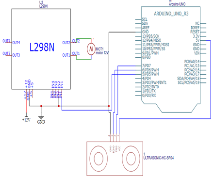
- Wire Diagram
This professional schematic diagram serves as a comprehensive guide for assembling and understanding the electronic circuit of the ‘ball levitation’ experiment. The integration between an Arduino UNO R3 microcontroller board, an L298N motor driver module, and an HC-SR04 ultrasonic ranging module is used in this experiment.
RESULT AND DISCUSSION
Simulation Results
Based on this mathematical and physical foundation equation (1), equation (2), and equation (4), the transfer function variables would like to be rooted in [2] which is illustrated in Table 5.
- Parameter choosing for variables in the transfer function
These variables are used for conducting research through this simulation for the ‘Ball Levitation’ experiment. According to Table 4, the transfer function would be finalized as the mathematics:

| (10) |
With the specific transfer function above, a “Ball Levitation” would like to be built as the Fig. 5. The PID structure in Fig. 6 is applied for the fuzzy PID embedded program in Fig. 7.

- Overall Ball Levitation Simulink Model

- PID Control Block

- Fuzzy PID Control Block
With set up parameters: simulation time 100 (s) and sample time 0.01 (s), the pre-processing and post-processing block as the result of the GA process like the Table 6.
- Pre and Post Processing of GA Simulation Result
K1 | K2 | K3 | K4 | K5 | K6 |
66.83 | 89.19 | 1.12 | 0.37 | 8.12 | 0.48 |
The PID parameter is also shown in Table 7.
- PID parameter
Comparison between PID and Fuzzy PID Control shown in Fig. 8.

- Comparison between PID and Fuzzy PID Control
Experimental Results
In this experiment, Arduino Uno is the core micro-processor and PWM is modified by L298N to control signal to a 12VDC Blower Fan to balance the desired set point of the ball through the value measured from ultrasonic sensor HC SR04. The “Ball Levitation” model component’s parameter as the Table 8.
- Component Parameters
No. | Component’s name | Specifications |
1 | Blower Fan | 12VDC |
2 | Arduino Uno | 5VDC |
3 | L298N | 12VDC |
4 | Ultrasonic HC SR04 sensor | 5VDC; Range: 20mm–500mm |
5 | Acrylic tube | Height: 500 mm; Radius: 50mm |
According to the conduction throughout the experiment, a comparison between controllers PID and Fuzzy PID can be easily recognized through Fig. 9. The quality of the system is shown in Table 9.

- Experimental Result Compare 2 Controllers
- The comparison between 2 controllers
Parameter | PID | Fuzzy PID |
% POT | 52.7 | 16.23 |
Settling Time | 223.79s | ~30.51 s |
Peak Time | ~170.7 s | 5.96 s |
Steady-State Error | 0.4563 | 0.2733 |
As indicated by the figure above, the experiment has been highly successful in demonstrating that integrating Fuzzy logic into a PID controller yields better results than the traditional ‘try and error’ method. Furthermore, the collaboration between GA and Fuzzy PID for optimizing the six pre- and post-processing parameters has proven to be superb in enhancing control within this model.
As easily seen at the desired set point Fuzzy PID can lessen POT, decrease steady-state error consistently, fall peak time, and settle time of this model significantly. However, when using a Fuzzy PID controller, the PWM at first is up and down sharply due to the rules of then this phenomenon disappearance in a short period of time and then this happening doesn’t matter much to the system as a result.
Based on the table above, the conduction of changing PID parameters to determine and ensure the truth of the rules that are used to define PID parameters at first. There are 6 cases to conduct research.
After the test, it can be easily realized that when rises steady-state (in Fig. 10) error is down steadily and the time for reaching the peak also decreases a little bit. In contrast, POT is a little bit when the decrease to 0.1 (in Fig. 11).
Through experimentation of changing Ki (in Fig. 12 and Fig. 13), the steady-state error is nearly eliminated completely, the ball keeps at a desired height and just small chattering.
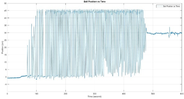
- Increase to 2
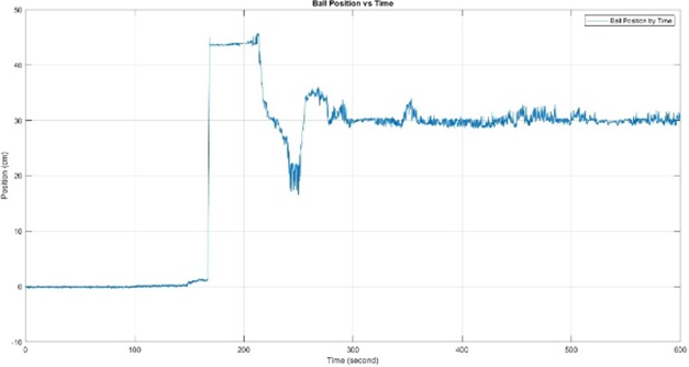
- Decrease to 0.1

- Increase to 1

- Decrease to 0.01
The final pilot study, in Fig. 14 and Fig. 15 play a crucial role in decreasing settle time and decreasing POT (%) steady-state error and peak time does not change sharply when modifying this parameter.

- Increase
 to 1
to 1

- Decrease to 0.01
conclusion
Both controllers work well with this model, despite its relatively simple design. The experiment on “Ball Levitating” was successfully built and designed. The results indicate that the Fuzzy PID controller exhibits better robustness compared to the ordinary PID controller. Investigating the pre-and post-processing blocks in the Fuzzy PID controller contributed significantly to this improvement. In future research, it would be beneficial to refine the fuzzy rules for specific cases and explore other types of fuzzy control, such as Mamdani, to further evaluate this model. For example, defining rules with the expertise of the designer and comparing Fuzzy PID with other control methods like Neural Fuzzy PID and Sliding Model, PSO Fuzzy PID would provide a more comprehensive understanding of this model. Moreover, with new integration of STM32F4 will bring better efficiency to the blower fan due to its effective PWM control.
Acknowledgment
We extend our heartfelt gratitude to Dr. Van-Dong-Hai Nguyen from HCMUTE for leading our research team and successfully concluding the project. The videos demonstrating the model's functionality can be viewed on the link:
- PID: https://www.youtube.com/shorts/ka5MkWKRDuQ
- Fuzzy-PID: https://www.youtube.com/shorts/xe4Ys2fwZHk
References
- Reza Masoudi et al, “Position control of two balls in two interconnected vertical tubes using controlled DC fans and sliding mode control,” 2014 International Conference on Mechatronics and Control (ICMC), pp 1629 – 1633, 2014, https://doi.org/10.1109/ICMC.2014.7231835.
- Ewelina Chołodowicz, and Przemyslaw Orlowski, “Low-cost air levitation laboratory stand using MATLAB/Simulink and Arduino,” Phil. Trans. Roy. Soc. London, vol. A247, pp. 529–551, 1955, https://doi.org/10.14313/PAR_226/33.
- Tomáš Tkáˇcik et al, “Design of Aerodynamic Ball Levitation Laboratory Plant,” Processes, vol. 9, no. 11, 1950, https://doi.org/10.3390/pr9111950.
- C. B. Kadu and C.Y. Patilb, “Design and Implementation of Stable PID Controller for Interacting Level Control System,” Procedia Computer Science, vol. 79, pp. 737-746, 2016, https://doi.org/10.1016/j.procs.2016.03.097.
- Liang Xiaoyin and Qu Beimin, “Fuzzy-PID controller,” IEEE Region 10 International Conference on Computers, Communications and Automation, pp. 296-299 vol. 4, 1993, https://doi.org/10.1109/TENCON.1993.320491.
- Ouyang Ziwei et al, "The experiment “Ball-in-tube” with Fuzzy-PID controller based on dspace," IEEE International Conference on Systems, Man and Cybernetics, pp. 877-881, 2007, https://doi.org/10.1109/ICSMC.2007.4413729.
- Jie Ma et al, "Parameters self-adjusting fuzzy PID control in magnetic levitation system," 2008 2nd International Symposium on Systems and Control in Aerospace and Astronautics, pp. 1-5, 2008, https://doi.org/10.1109/ISSCAA.2008.4776264.
- B.-H. Nguyen et al, “Application of Genetic Algorithm for Optimizing Continuous and Discrete PID to Control Antenna Azimuth Position”, JFSC, vol. 2, no. 1, pp. 1–5, 2024, https://doi.org/10.59247/jfsc.v2i1.154.
- S. N. Vassilyev, A. Y. Kelina, Y. I. Kudinov, and F. F. Pashchenko, “Intelligent control systems,” Procedia Computer Science, vol. 103, pp. 623-628, 2017, https://doi.org/10.1016/j.procs.2017.01.088.
- L. Q. Tran, Y. Sun, R. Guan, J. Saeed, L. Wang and P. J. Radcliffe, "Development and Outcomes of Teaching PID Control in Classroom with Hands on Learning Experience," 2019 IEEE International Conference on Industrial Technology (ICIT), pp. 1041-1047, 2019, https://doi.org/10.1109/ICIT.2019.8755227.
- R. P. Pratama, A. Rusdinar and I. P. D. Wibawa, "Floating Robot Control System for Monitoring Water Quality Levels in Citarum River," 2019 IEEE International Conference on Internet of Things and Intelligence System (IoTaIS), pp. 206-211, 2019, https://doi.org/10.1109/IoTaIS47347.2019.8980393.
- A. Kumar et al, "Designing of an interval type-2 fuzzy logic controller for Magnetic Levitation System with reduced rule base," 2012 Third International Conference on Computing, Communication and Networking Technologies (ICCCNT'12), pp. 1-8, India, 2012, https://doi.org/10.1109/ICCCNT.2012.6395883.
- N. Magaji and J. L. Sumaila, "Fuzzy logic controller for magnetic lévitation system," 2014 IEEE 6th International Conference on Adaptive Science & Technology (ICAST), pp. 1-5, 2014, https://doi.org/10.1109/ICASTECH.2014.7068112.
- M. K. A. A. Khan et al, "PID Controller design for a Magnetic Levitation system," 2018 IEEE 4th International Symposium in Robotics and Manufacturing Automation (ROMA), pp. 1-5, 2018, https://doi.org/10.1109/ROMA46407.2018.8986710.
- K. Poomani et al, "Implementation of CDM based PID Controller for Magnetic Ball Levitation System", 14th IEEE India Council International Conference, pp. 1-5, 2017, https://doi.org/10.1109/INDICON.2017.8487235.
- Amirreza Tootchi et al, " Modeling and Control of an Air Levitation Ball and Pipe Laboratory Setup," International Conference on Robotics and Mechatronics (ICRoM 2019), pp. 29-34, 2019, https://doi.org/10.1109/ICRoM48714.2019.9071827.
Hoang-Thuat Nguyen, Experiment Ball Levitation with Fuzzy PID and PID Implementation


