,
,  , and
, and  based on the transient phase reaction, it included a closed loop and an open loop through which the basics, process gain (), process time constant (
 ), dead time (
 ) are obtained using the
  tuning method using different rules.
 Journal of Fuzzy Systems and Control, Vol. 2, No 3, 2024 |
Fuzzy Logic-based PI Controller with PWM for Buck-Boost Converter
Zainab Ameer Al-Dabbagh 1, Salam Waley Shneen 2,*, Abduljabbar O. Hanfesh 3
1 Department of Construction and Projects, Ministry of Higher Education and Scientific Research, Baghdad, Iraq.
2 Energy and Renewable Energies Technology Centre, University of Technology-Iraq, Baghdad
3 Electromechanical Engineering Department, University of Technology-Iraq, Baghdad
Email: 1 zainabameer1971@gmail.com, 2 salam.w.shneen@uotechnology.edu.iq,
3 abduljabbar.o.hanfesh@uotechnology.edu.iq
*Corresponding Author
Abstract—Electronic power converters have emerged and been widely used as a result of the use of direct current systems, and one of their most important uses is renewable energy such as solar energy. When electrical energy is generated from primary sources such as solar energy, converters can be added to convert to a higher or lower value using a buck-boost converter. If the converter is used and operated within an open-loop system, which is the first proposed test case, it is possible to verify the ability of the converter to convert with a constant current rate according to its function, but it turns out that the conversion, in this case, is in a state of instability, which requires work to add feedback and make the system operate in a system Closed loop is the second test case to reach and ensure a stable state for the system. To ensure the scheduled effort, work is being done to improve the system by adding traditional and expert controllers. Thus, by adjusting the parameters of the controller, acceptable performance can be obtained. It represents a transformer with a controller that maximizes results with accuracy and stability. The controller works to track errors through a sensor. It shows the output value with the appropriate reference value for the transformer output, in addition to the presence of a comparator that detects the error to be an input for the controller, which works according to a working algorithm to implement a compensation state, treat the error and instability, get rid of the deviation, and return to the stable state. Various control methods are implemented to improve performance, including traditional PI and expert Fuzzy, with the best being determined by comparing the system output results, as the simulation showed the superiority of fuzzy logic over traditional in terms of response speed time, rise time, and under and over bypass rates.
Keywords—Buck-boost DC-DC Converter; Pulse Width Modulation (PWM); Proportional-Integral (PI); Tuned Proportional-Integral; Fuzzy Logic Control (FLC)
Power electronic converters are used in many different types of applications [1]-[4]. It includes the inverter, which is the converter that works to convert direct current (DC) into alternating current (AC) [5]-[7]. Also, there is another type that works to convert alternating current into direct current (AC-DC) [8]-[10], as well as other converters such as the (AC-AC) type converter, in which the converter input has a fixed value with change the output value [11]-[13]. In addition to converters of the type (DC-DC), the converter's input value is fixed as the output value changes. Some converters are single-phase and others are three-phase [14]-[16]. Among them are step-up converters and there is a type called step-down converters. A buck-boost converter is a combination of a basic buck and boost converter. They are known as step-up and step-down converters, where the output voltage is lowered/raised to a specific level and according to what is required, higher or lower than the input. Since the diode in the converter is in the opposite direction, the polarity of the output voltage is opposite to the input voltage. The regulators were used to detect the output voltage and adjust the power transmission phase. The control process is done using a feedback loop to maintain that regulation. When the circuit can function as a buck converter or boost converter, it can be used in applications where the source voltage is variable [17]-[19]. The buck-boost converter is implemented in various fields such as grid-connected photovoltaic systems and motor drives. The researchers studied some types of DC-DC converters to increase the efficiency of converters and voltage gain for widespread use in solar energy applications. The outages in the transformers were analyzed and a new compensation technique was used to find solutions during changes in the transmission conditions [20][21].
In [22], a new converter was proposed that represents an alternative in solar energy applications with multiple points and depends on the associated inductances, possibly increasing or decreasing the voltage between any two points via direct current. In [23][24], researchers presented a time-average model in a proposed converter, and a non-inverting converter with high efficiency was proposed to provide system voltage that can be used in a wide range of electronic applications using an easy-to-use control method. In [25], [26], direct current converters were designed and simulated, including equations for the basic parameters in the circuit and conducting theoretical derivations by performing simulations of buck, boost, and buck-boost converters and changing the values of inductance, capacitance, and switching frequency to monitor changes in the output voltage and performing a study of the output voltages with variable the parameters.
A buck-boost converter with proportional-integral (PI); and fuzzy logic (FLC). controllers are provided and the circuit is simulated using MATLAB to prove the circuit's functionality. In section III, how to design the buck-boost converter circuit was carried out to choose the parameters in the circuit. In section IV, the simulation of the Controller for a non-linear was carried out using the open loop and the closed loop. In section V, the results of simulations and comparisons were made in the closed-circuit case for the proportional control unit and the fuzzy logic unit. In section VI, the conclusion is presented for the MATLAB program. In addition to another section (section VII), the conclusion.
Proportional Integral Derivative (PID) controllers, due to the simplicity and ease of the PID controller, have been used in industrial control applications when the speed of movement of the controlling system is not essential to the system’s operation. The total output consists of the elements (proportionality, integration, and differentiation), and t these elements depend in their work on the existence of the error value e between the input and the output. The concept of controlling the average value of switching variables in each cycle and PI control is used in some battery-operated systems, because a large change in the input voltage may occur, starting from a full charge and decreasing until the input voltage drops below the level required by the circuit. Therefore, it is better to find an alternative, which is a boost regulator. Some researchers have suggested that many industrial processes have gradual responses [27]-[29].
In [30][31], it was proposed to perform the gain conversion process using artificial intelligence, it observed the process of converting a DC-DC buck-boost to a direct current motor load using fuzzy logic and integral differential (PID) controls to determine ideal duty cycles so that wasted energy can be reduced.
Tuning PID parameters requires obtaining the circuit configuration to perform the adjustment process, as the control units depend on the transfer function variables. The researchers presented methods like Ziegler and Nichols, Cohen-Coon and Åström and Hägglund.
The first method represents the adjustment proposed by Ziegler and Nichols, which is basic and widely known. They presented multiple studies and rules for calculating the values , , and based on the transient phase reaction, it included a closed loop and an open loop through which the basics, process gain (), process time constant (), dead time () are obtained using the tuning method using different rules.
The second method is tuning Cohen-Coon: which used the technique and PID controller parameters from, First Order plus Time Delay (FOLPD) proposed to eliminate load disturbance.
In the third method, researchers Åström and Hägglund used gain and phase. Compared to the test, this method is easy to use and represents an improvement for automatic loop tuners. The variable relative gain was replaced by a non-linear function, in addition to the gain and phase approach to obtain specific points on the Nyquist curve, which contributed to helping the control unit tuning parameters by reducing errors, and also helped to change the point critical on the Nyquist curve.
Also, other researchers proposed modifications to adjustment methods. Åström and Hägglund proposed an improved Ziegler and Nichols tuning method for loop configuration, and the Hrones and Reswick (CHR) technique was created from the original Open Loop technique. This technique responds faster without overshooting [32]-[35].
Fuzzy Logic Controller, the fuzzy logic controller technology has been applied in many electronic devices and computers, which include artificial intelligence, and to further improve its performance, a genetic algorithm was used to organize the design of the fuzzy controller, so it is considered an alternative to contemporary control systems with a fast and stable system response. Three stages are involved in using fuzzy logic to build a control system: fuzzification, rule evaluation, and defuzzification, and each stage has an impact on the system's response. Fuzzy logic has been applied to microcontroller robots, which make decisions about how to apply Particle Parameter Swarm Optimization (PSO) in a given situation based on behavior, in addition to its applications in controlling load lifting using fuzzy logic commands by adding commands to tune the communication between controllers and motion. Lever and cap are widely used in ambiguous controllers for physical computing platforms due to their ease of application. It is in addition to other applications, which include the stabilization mode in the movement of limbs and clamps to lift classified parts such as variable loads (small, medium, large) and the method of controlling and controlling their movement. After that, other researchers proposed many methods using the fuzzy logic control unit for robots, which they used to lift parts with Different loads. Determining the parameter values in the input, specifically, the sensitivity to the types of loads of the models, will enable the controllers to deal smoothly and flexibly with nonlinear and dynamic systems. Researchers illustrate through their studies the difficulties of optimizing fuzzy sets and rules with dynamic network changes [36]-[38].
When exploring some semiconductors, specifically transistors, and thyristors, due to their high switching speed when used as electronic switches, in addition to their thermal stability and low resistance, they are therefore used in the construction of electronic power converters, providing the possibility of obtaining a highly efficient, lightweight transformer and an effective model of quality and high performance. By developing appropriate design and testing of DC/DC buck-boost converters [39]-[42]. Pulse Width Modulation (PWM) technology can be used with electronic transformers such as the Buck-Boost transformer, providing the ability to switch according to the load, i.e. according to operating conditions, and to obtain an improvement in the performance of the electronic power converters [45]-[47]. Power electronic transformers are used in various applications because of their advantages over conventional transformers in terms of cost, efficiency, losses, and size. It is one of the widely used converters in industrial applications with electric motors because it provides high performance at low speeds and gives higher dynamic response and reliability. The proposed PWM converter is described as a converter whose function is to change the voltage value from a fixed voltage to a variable voltage while providing both switching states, which raises or lowers the output value from the value associated with the power supply of the converter on the input side [48]-[50]. It consists of a group of active elements, such as semiconductors such as transistors and thyristors, and others that are inactive or inactive, such as the conductor and coil, which are included in the design of the converter. The transformer is chosen to boost low converter input to high output or high to low voltage depending on the desired level of transformer output [51]-[54].
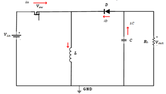
The buck-boost converter circuit includes (an inductor, a switch, a diode, and a capacitor) these are considered necessary for controlling the flow of current, the voltage of output is determined by determining the input voltage, the duty cycle ( ), and the switching time interval. The duty cycle affects significant and direct voltage output. The pulse width modulation PWM controls the operation of the opening and closing switch, the MOSFET, or the transistor, and this will affect the amount of power transferred to the output efficiently [55]-[57].
The buck-boost converter operates in two states, which depend on the value of this duty cycle. The first case is to be in a state of raising the voltage value, where an output voltage is obtained with a value greater than the value of the input voltage. The second case is in which the value of the output current is intended to be less than the input current. The step-down converter works in the opposite direction to the circuit of the step-up converter, which means that the output voltage is less than the input voltage used, so the output current is greater than the input current [58]-[61]. The circuit can be reorganized by combining the two modes and redesigning the circuit. To obtain a converter that can use a wide range of input voltage in the case of higher or lower than the output voltage depending on the work requirements. As shown in Fig. 1, the parameters of the two circuits are linked with the addition of a module The controller senses the amount of input voltage to ensure proper operation of the integrated circuit [43].
Fig. 2 shows a typical Buck-Boost converter circuit, The transition states of the back-post converter circuit are fast and depend on the cases that the circuit is going through, and the value of the duty cycle has a significant impact on changing states and work in the circuit, as shown in Fig. 3 [44].
It is similar in configuration to a flyback converter but uses one inductor instead of a transformer. These converts are easy to build. The Converter works in two states: In the first state switch is on and conducting, and the diode is off. They analyzed steady-state operation for this mode using KVL :
| (1) |
| (2) |
| (3) |
Since Switch is closed for a time Ton = DT, it can be said that: Δt = DT.
| (4) |
The second is when the switch is off and the diode is on.
The analysis in steady-state operation
| (5) |
| (6) |
| (7) |
Because Switch open for a time
| (8) |
It can see the rate of the change in the inductor current
| (9) |
| (10) |
| (11) |
| (12) |
From the equations above, it is clear that the duty cycle controls the output voltage and can be calculated for the buck-boost converter according to the following formulas:
When the duty cycle exceeds 0.5, it can be seen that the value of the output voltage is greater than the source voltage. Still, when the duty cycle falls below 0.5, it can be seen that the value of the output voltage is less than the source voltage, and if the value of the duty cycle is equal to 0.5, the source and output voltages are equal.
Choosing the appropriate value for the inductance in the circuit is necessary because it affects the number of ripples occurring in the output voltage, in addition, it shows the state of conduction. The equations below represent the basic elements for calculating the amount of inductance in the circuit.
The operation of the capacitor in the circuit is necessary for the stability of the voltage, as well as reducing the amount of interference at high frequencies. It also indicates the state of ripples in the input and output voltages, so choosing the appropriate value is very important.
To design a Buck-boost Converter: the input voltage (18volt), output voltage (12volt), frequency switch(40khz), output resistance (10 Ω), and ripple output voltage (1%), it can calculate the parameters:
Duty cycle
| (13) |
| (14) |
The rate value of the Duty cycle is:
|
Minimum inductor:
| (15) |
The rate value of the Minimum inductor is:
|
Minimum capacitor:
| (16) |
The rate value of the Minimum capacitor is:
|
Inductor current:
| (17) |
| (18) |
Rate value of inductor current
|
Rate of change inductor current:
| (19) |
Rate value of change inductor current:
|
Minimum inductor current:
| (20) |
The rate value of the Minimum inductor current is:
|
In a single-switch buck-boost (SSBB) converter, there are three important types of electronic power converters for converting constant value direct current to variable value, including buck, boost, and buck-boost.
Suggested tests First, the system state when it is an open loop system, in which the voltage is converted from 18 volts to 12 volts to identify the system behavior and determine the performance measures by displaying the results in a form and table, as will be stated later in the following paragraphs. The second test case is to operate the system in another different state by adding feedback specifying a reference value for the specified voltage with a sensor for the output value and a comparator that shows the state of the error as a result of the system disturbance, it can be returned to the stable state by adding the traditional controller to provide the appropriate response speed. Among the other test cases, an expert controller can be chosen as a result of the change required by the transformer's operation in different operating states, which are considered a nonlinear system, such as converting the voltage from 18 to 12 or 25, which will be simulated now in the next step below:
The current test is an open loop system test for the available input voltage converter 18 and the required output voltage is 12 volts. The change in the oscillation value can be observed between a slightly lower or higher value which is explained in the mathematical calculations in the model design.
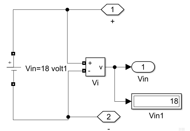
A simulation model of a Buck Boost-type power converter with a load and a power source is being built and designed. The source voltage is 18 volts with a load of 10 ohms. The required test is to test the behavior of the system when the output of the converter is higher than its input, for example, the output is 25 volts. Another test case is to be lower than the input, for example, 12 volts. A third test case is to have half of the operating period less than the input and the other half higher than the input of the converter, i.e. 25 volts and 12 volts.
Table 1 shows the basic values of the buck-boost converter's parameters. The simulation is performed on the circuit using pulse width modulation (PWM) as shown in Fig. 4. The waveforms are shown in Fig. 5. The simulation result is shown in Table 2.
The proposed tests can be performed with a choice of open loop and closed loop system, conventional controller at one time and expert controller at another time, as will be detailed later. The proposed tests require system modeling and mathematical calculations based on the input and output of the converter to determine the appropriate system parameters such as capacitance and inductance.
The first test uses model number one as in Fig. 4 which represents the system operation in the open loop state, i.e. without feedback and without a reference value, and its behavior depends on the parameter values, and therefore we may not get the best performance. In the second test after identifying the system behavior for the first case, work is underway to develop other test cases to develop the model and improve performance through measurement criteria such as stability, response speed, rise time, and overshoot and undershoot rates. What improves performance is adding feedback and a control unit, as the test included two cases, the first with a traditional control unit (PID) and the second with an expert control unit (fuzzy logic).
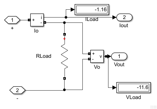
In the simulation response Buck-Boost converter by MATLAB Simulink open loop using (PWM), Vin=18v, Vout= -11.6v, Iout= -1.14amp, Pout= 13.45watt that show the Output voltage, current, and power of the open loop circuit.
(a) A single-switch buck-boost converter |
(b) subsystem of DC Source |
(c) subsystem of Buck-Boost Converter |
(d) subsystem of Load |
Parameters | Symbol | Value |
Input voltage |
| 18v |
Output voltage |
| 12v |
Output resistance |
| 10Ω |
Switching frequency |
| 40khz |
Ripple of output voltage |
| 0.01 |
Duty cycle |
| 0.4 |
Minimum inductor |
| 45µH |
Minimum capacitor |
| 100 |
Inductor current |
| 2amp |
Rate of change inductor current |
| 2.67 amp |
Minimum inductor current |
| 0.67 amp |
(a) Waveforms of output voltage, current, and power of the open loop circuit at the time (0-0.05) |
(b) Waveforms of Output voltage, current, and power of the open loop circuit at time (0.2250-0.2256). |
Details | Output Voltage | Output Current | Output Power | |
Rise time | --- | 83.42 | 33.650 | |
Slew time | --- | 1.138 | 283.555 | |
Fall time(µsec) | 117.376 | 6720 | 1.033 | |
Slew rate(/ms) | -75.973 | -1.475 | -9.234 | |
Preshoot% | --- | 18.452 | 10421 | |
Overshoot% | --- | 0.595 | 138.653 | |
Unedshoot% | --- | 0.595 | 1.542 | |
Setting time(ms) | --- | --- | --- | |
Preshoot% | 4.630 | 0.595 | 144.64 | |
Overshoot% | 0.013 | 0.471 | 4.772 | |
Unedshoot% | 80.556 | 18.452 | 4.285 | |
Setting time(ms) | 2173 | --- | --- | |
The PI control unit represents a closed-loop system, so it does not require manual input, it provides a faster response time than I-only control due to the addition of the proportional action. It is a set of devices and commands that regulate the process variable to obtain a constant and desired output voltage without distortions and ripples. Fig. 6 shows how the PI control unit works in a closed circuit, starting by using the output signal as feedback for modification and correction, then comparing it with the signal that is entered, which crosses a reference, and by comparing the two signals, a signal called error is created, which is entered into the control unit for adjustment and correction, includes the terms proportional (Kp) and integral (Ki). Control o/p u is the sum of proportional and integral gains [29][44], the equation below represents the PIC:
| (21) |
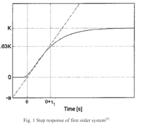
Fig. 7 shows the buck-boost converter is controlled from the PI controller techniques [29]. The existent types of adaptive techniques are classified based on the variety of process dynamics. The controller should solve these variations by adapting their parameters. There are two types of process dynamics variations, predictable and unpredictable. These are caused by nonlinearities and can be handled using a gain schedule, which means that the controller parameters are found for different operating conditions with an auto-tuning procedure that is employed thereafter to build a schedule. Most classical techniques make assumptions about the plant model and try to derive the controller settings for these general models. To determine the dynamics of these systems, the step response of the systems is obtained. This response is characterized by different equations, using which different classical methods have been developed. The researchers propose that many industrial processes have step response. Where  is the static gain, θ the dead time, and τ1 the time constant. The parameter a is determined by the intercept of the line (tangent to the graph) with the y-axis and θ the x-intercept. fluctuations that may occur due to its ability to restore and adjust the system [44][62], as shown in Fig. 8.
| (22) |
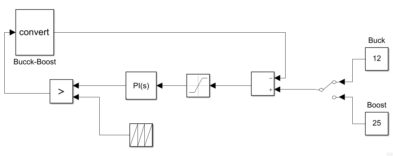
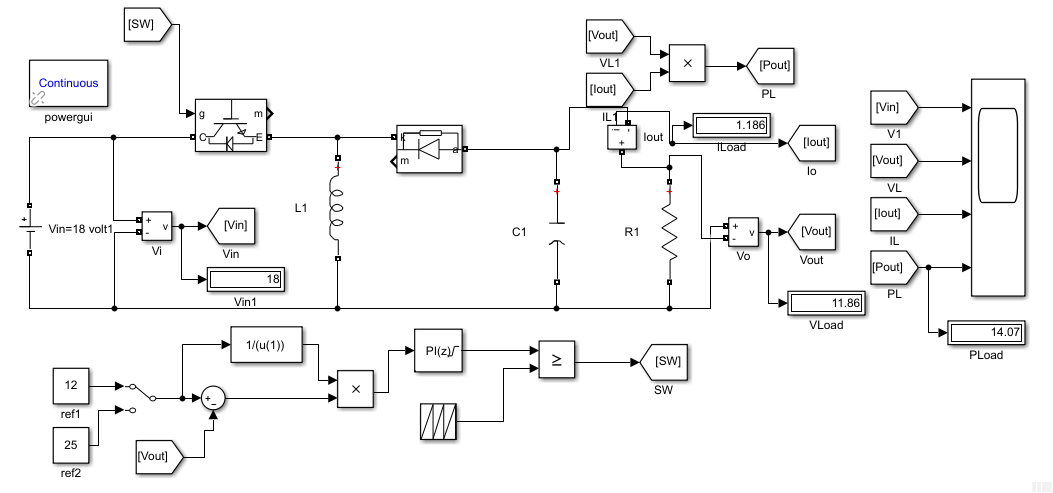
Test No. 2 System status closed loop converter input 18 volts and required output 12 The model is designed with the addition of feedback and a conventional control unit as in the simulation model in Fig. 9 (a).
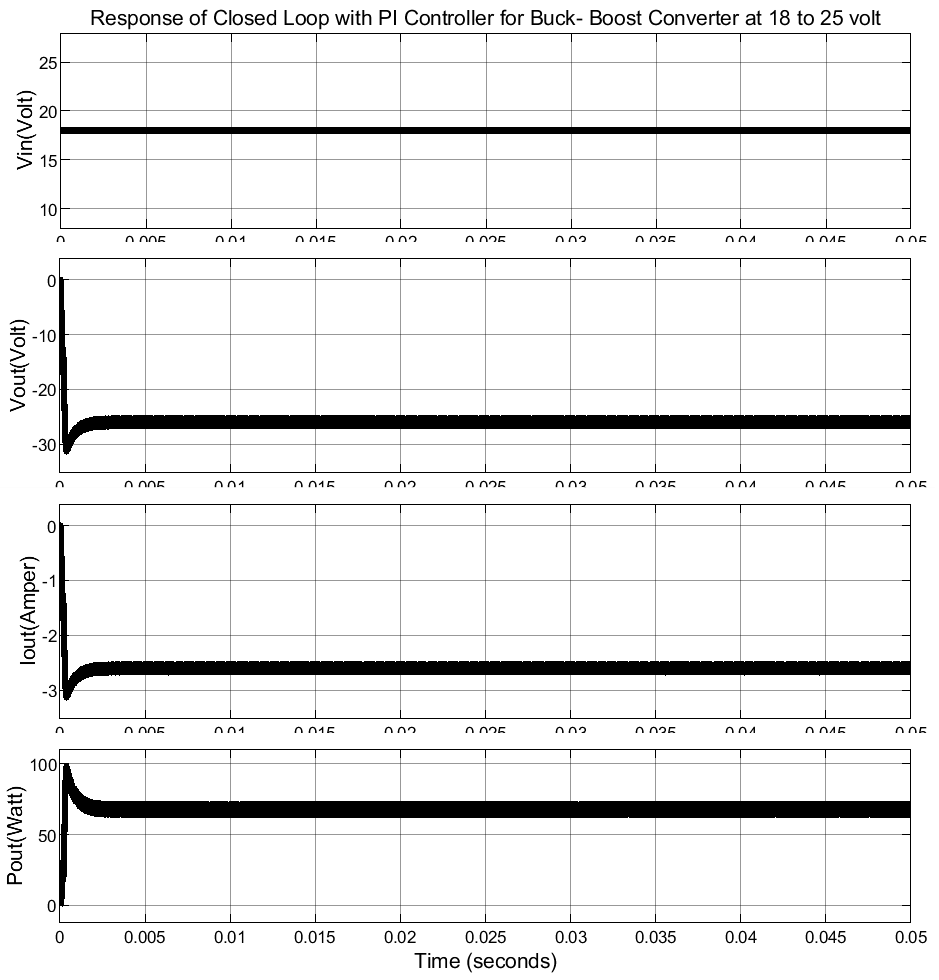
Test No. 3 System status closed-loop converter input 18 volts and required output 25 The model is designed with the addition of feedback and a conventional control unit as in the simulation model in Fig. 9 (b).
Test No. 4 System status closed-loop converter input 18 volts and required output 12 for half the period and 25 for the other half with the addition of feedback and a conventional control unit as in the simulation model in Fig. 9 (c).
For the load regulation of the buck-boost converter. The duty cycle (input ) determines the percentage of the pulse period that the output ( ) is on Switching frequency 40khz, and zero sample time. That is shown in Fig. 9 and the waveforms are shown in Fig. 10 (a), and Fig. 10 (b). The result of the simulation is shown in Table 3 and Fig. 11 to Fig. 13.
Details | Output Voltage | Output current | Output power |
Rise time(ns) | --- | --- | 816.904 |
Slew time | --- | --- | 351.081 |
Fall time(ms) | 2.002 | 2.002 | 9.529e-03 |
Slew rate(/ms) | -3.739 | -3.739 | -30.098 |
high | -3.051e+00 | -3.051e-01 | 1.518e+01 |
low | -1.241e+01 | -1.241e+00 | 1.482e+01 |
Amplitude | 9.357e+00 | 9.357e-01 | 3.585e-01 |
Signal statistics | |||
Max | 5.273e-03 in time (2.00e-05)sec | 5.273e-04 in time (2.00e-05)sec | 1.55e+01 in time (0.042s) |
Min | -1.247e+01 in time ( 0.036)sec | -1.247e+00 in time ( 0.036)sec | 1.482e+01 in time (0.027s) |
Peak to Peak | 1.248e+01 | 1.248e+00 | 7.316e-01 |
Mean | -1.183e+01 | -1.183e+00 | 1.518e+01 |
Median | -1.230e+01 | -1.230e+00 | 1.518e+01 |
RMS | 1.198e+01 | 1.198e+00 | 1.518e+01 |
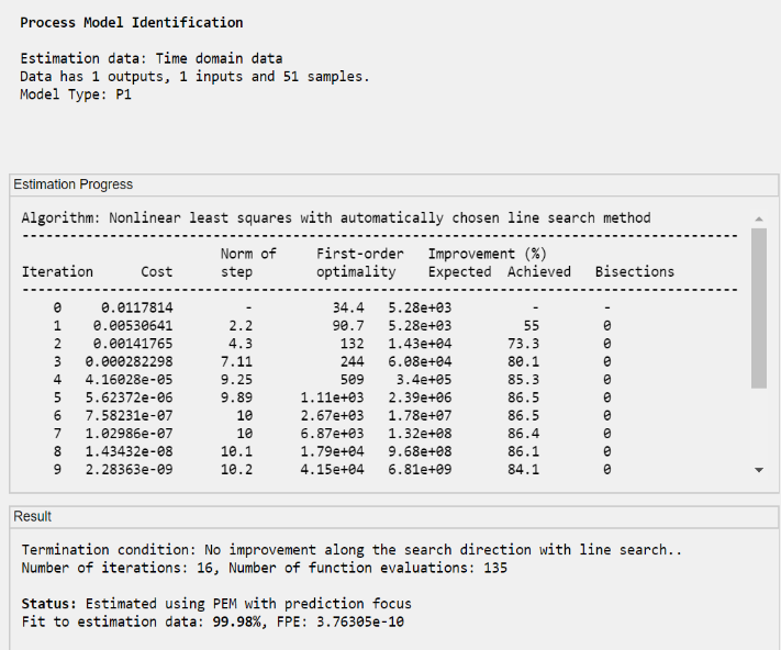
The tuning state in the PID controller is widely used in the closed-loop state. It is necessary to maintain and stabilize the resulting output value and set it at a specific point, which represents the lowest value of the tuning requirements. Therefore, it can be shown that the control unit is operating in a steady state by using the tuning method by adjusting the circuit as shown in Fig. 14 to Fig. 16 of the simulation models and wave diagrams of the results, which show the values through which appropriate and satisfactory results were obtained for operating the circuit.
(a) Closed loop 18 t0 12 volt |
(b) Closed loop 18 t0 12&25 volt |
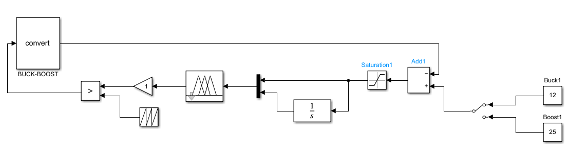
Fuzzy Logic Controller (FLC): This unit is considered one of the most widely used in the control system, as fuzzy logical reasoning is used in applications that replace digital systems where the function is used with fuzzy sets. The base system contains four parts, as shown in the general structure of the FLC in Fig. 17, and Fig. 18, where it consists of four parts (complexity, rules, fuzzy dissimilarity, and fuzziness removal) [29].
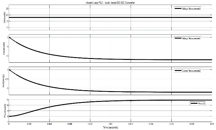
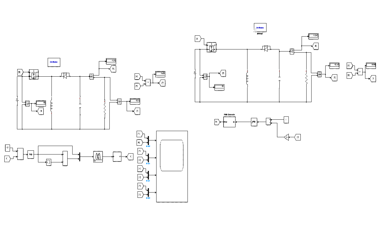
Fig. 19, Fig. 20, and Table 4 show a buck-boost converter circuit using controlled fuzzy logic with waveforms for the output voltage, current, and power.
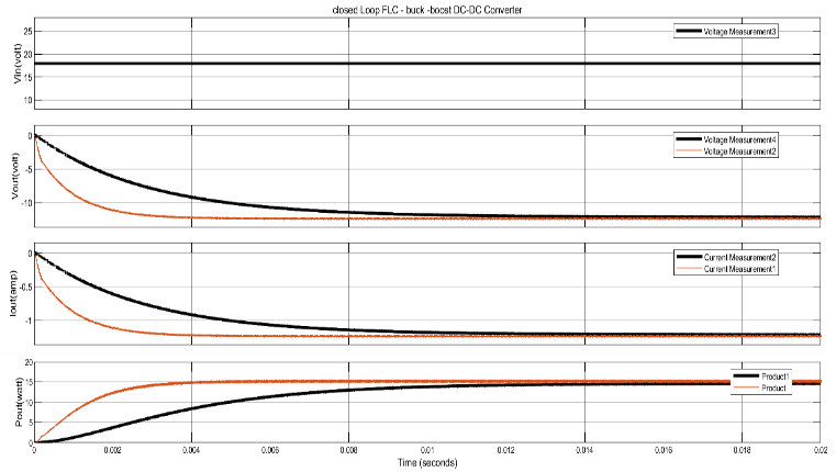
It was observed that the ability and superiority of the controlling fuzzy logic in working and adjusting the output voltage was achieved from the change in the output voltage referring to increase and decrease as follows (40 volts, 25 volts, and 10 volts). The output voltage value remains stable at 12 volts, as shown in Fig. 21, and the resulting waves in Fig. 22. In Fig. 23, the two circuits are drawn in the two cases: PI controller, and FL controller. Also, their waves are combined as in Fig. 24 (a), and Fig. 24 (b) to show the differences between the circuits for the two cases. As shown, the superiority of the fuzzy logic over the integral derivative circuit.
(a) The time (0- 0.02) sec |
(b) The time (0.0075-0.011) sec |
Details | Output Voltage | Output Current | Output Power |
Rise time(ns) | --- | --- | 7.096 |
Slew time | --- | --- | 1.632 |
Fall time(ms) | 5.962 | --- | --- |
Slew rate(/ms) | -1.201 | --- | --- |
high | -3.083e+00 | 1.800e+01 | 1.455e+01 |
low | -1.203e+01 | 1.800e+01 | 7.310e+01 |
Amplitude | 8.948e+00 | --- | 1.447e+01 |
Signal statistics | |||
Max | 4.250e-04 in time (1.25e-05s) | 4.250e-05 in time (1.25e-05s) | 1.462e+01in time (0.020s) |
Min | -1.209e+01in time (0.02s) | -1.209e+00in time (0.02s) | 1.273e-35 in time (000e+00s) |
Peak to Peak | 1.209e+01 | 1.209e+00 | 1.462e+01 |
Mean | 1.209e+01 | 1.209e+00 | 1.141e+01 |
Median | -1.175e+01 | -1.175e+00 | 1.381e+01 |
RMS | 1.068e+01 | 1.068e+00 | 1.223e+01 |
(a) The time (0.002-0.02) sec |
(b) The time (0.004-0.016) sec |
(c) The time(0.005-0.0085) sec |
A buck-boost converter circuit was selected and the output voltage, current, and external power were implemented. The simulation was conducted using MATLAB software accordingly and based on the parameters shown in Table 1, after implementing the buck-boost circuit design in three cases, a signal with a frequency of 40 kHz and an input voltage of 18 V DC. The results obtained were noted:
In the case of an open loop, the results showed that the output voltage reaches a value close to the required voltage with a negative value and stabilizes at a value of (-11.74 volts) as shown in Fig. 4, and Fig. 5, still, there are ripples in the output voltage, response time, and stability time. In the closed-loop case, the PI controller was used before and after tuning the wave to obtain results in the output voltage close to the required value, the output reaches (-12.19 volts) as shown in Fig. 7 to Fig. 16. In the case of the FL controller, the output voltage reached (-12.09 volts), but with a shorter and different response time and stability time, as the output voltage wave begins to fluctuate slightly until it stabilizes at a value of (-12.09 volts) and the current reaches (-1.209 amps) as shown in Fig. 19, and Fig. 20. The two waves were drawn together in both cases as shown in Fig. 23. Fig. 24 (a), Fig. 24 (b), Fig. 24 (c) to show the extent of the change in the waves (voltage, current, and power) to illustrate the importance of this system and its modification through the controller and sensor, as well as getting rid of excess and unwanted current and oscillation conditions, which resulted from the simulation. Some parameters for the circuit were chosen by changing the output value, then conducting simulations and monitoring the changes that occur in the output result through the graph, where it was proven to obtain the same required output parameter, which represents. (12 volts) as shown in Fig. 21, and Fig. 22.
The results demonstrated the ability and superiority of the fuzzy logic controller, it is possible to check other parameters in the circuit. This is shown in Effective working faster orders, adapting power, and improving the network. A buck-boost converter provides an output voltage that may be less than or greater than the input voltage. In this study, a DC-DC buck-boost converter was used in two states, open circuit and closed circuit improving the operation of the converter. The load demand was regulated and the overshoot and settling time were reduced with a faster response. The converter was used in a feedback loop to maintain regulation and indicate the status of the output voltage. The tuning of the power transfer state. This led to exploring different characteristics of converters by connecting the traditional proportional integral controller (PIC) and the fuzzy logic controller (FLC). The results obtained were compared, which showed the efficiency and adaptability of the fuzzy logic controller, its response speed, and its ability to improve. Adaptation by modifying the structure of the system, its rules, and how to deal with all cases. In addition, the control case was carried out for the results were reached through the traditional proportional-integral control unit (PIC). Finally, the results were presented for each case using the MATLAB/Simulink program, and then the performance of those cases was evaluated.
After conducting the proposed tests, the effectiveness of the system and the possibility of obtaining the required output for changing the load at the specified voltage with the appropriate design were verified. It was also found that the used transformer has high efficiency and is suitable for different applications similar to its operating specifications, such as electric vehicles, computers, elevators, satellites, engines, trains, water pumps, etc.
From the test results, a model with high quality, improved performance, and high-level efficiency could be designed. The results showed that the fuzzy logic circuit was compatible, resulting in a low time error in the average rise. The time to reach the steady state was faster than the PI control and was slightly wavy while the PI control took a long time.
The possibility of raising or lowering the output value was verified according to the test results. The effectiveness of the model and the possibility of designing suitable transformers for different applications were verified. The possibility of improving performance using conventional and expert control systems was verified.
Zainab Ameer Al-Dabbagh, Fuzzy Logic-based PI Controller with PWM for Buck-Boost Converter