(1)

(2)

(3)

(4)
Journal of Fuzzy Systems and Control, Vol. 1, No 1, 2023 |
Adaptive Fuzzy-PI for Induction Motor Speed Control
Hari Maghfiroh 1*, Joko Slamet Saputro 2, Fahmizal 3, Muhammad Ahmad Baballe 4
1, 2 Department of Electrical Engineering, Universitas Sebelas Maret, Surakarta, Indonesia
3 Department of Electrical Engineering and Informatics, Vocational College, Universitas Gadjah Mada, Yogyakarta, Indonesia
4 Department of Computer Engineering Technology, Kano State Polytechnic, Kano State, Nigeria
Email: 1 hari.maghfiroh@gmail.com, 2 jssaputro89@staff.uns.ac.id, 3 fahmizal@ugm.ac.id, 4 mbaballe@kanopoly.edu.ng
*Corresponding Author
Abstract — An induction motor (IM) is one type of AC motor which widely used. IM is chosen due to its simplicity, reliability, efficiency, and low cost. There are many methods proposed to control the speed of IM which is known as variable speed drive (VFD). In this study, the DTC method is used since it is more robust to the parameter’s changes. The combination of the Fuzzy and PI method is used in speed control. PID performances decrease when the system condition changes. Therefore, fuzzy is used as an adaptive algorithm to vary the PID gain. It was superior in terms of settling time, overshoot/ undershoot, and IAE compared to the PI method. It has lower IAE in both speed tracking and loaded conditions by 44.98% and 4.47%, respectively.
Keywords—induction motor, speed control, PID, fuzzy
An induction motor (IM) is one type of AC motor which widely used. It can be found in an industrial or electric vehicle as a traction motor [1]. According to [2], IM is chosen due to its simplicity, reliability, efficiency, and low cost. There are many methods proposed to control the speed of IM which is known as variable speed drive (VFD). Fig. 1 shows the resume of the method of VFD. It is classified as a sensor less and sensored method. In this study, sensored control is chosen since it is simple and easy to implement.
Scalar control and vector control are two subcategories of the sensored approach. Scalar control has a straightforward architecture and poor precision [3, 4]. Vector control, on the other hand, is intricate and provides excellent performance [5-7]. This is the rationale behind using vector control in this investigation. There are two classes of vector control: Direct Torque Control (DTC) and Field Oriented Control (FOC) (DTC). Faster reactions and high efficiency characterize FOC. The approach is highly sensitive to changes in the parameter, though. DTC, on the other hand, provides good performance and consideration for parameter variation [8].
Because the FOC and DTC only regulate torque, additional control methods are required to control IM's speed. Proportional Integral Derivative (PID), Fuzzy Logic Control (FLC), Sliding Mode Control (SMC), Artificial Neural Network (ANN), Linear Quadratic Gaussian (LQG), and also a combination of conventional and artificial method as in [14, 15] are just a few of the speed control methods for IM that have been proposed by researchers.
In this study, the DTC method is used since it is more robust to the parameter’s changes. The combination of the Fuzzy and PI method is used in speed control. According to [16], PID performances decrease when the system condition changes. Therefore, fuzzy is used as an adaptive algorithm to vary the PID gain. This article is organized as follows. In Section II, the DTC and Fuzzy-PI are reviewed. Results and discussion are presented in Section III. The last Section IV concludes this study.
In the DTC method, the primary controlled variable is the stator flux vector as in (1) – (4). Where λs, vs, rs, ares stator flux, stator voltage, stator resistance, and stator current respectively. While subscript qs and ds in the flux and current means the results from DQ-transformation. With the right choice of a voltage reference, the magnitude and angle can be adjusted because vs can be controlled by it.
| (1) |
| (2) |
| (3) |
| (4) |
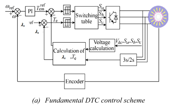
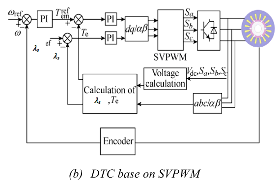
DTC additionally dissociates flux and torque for improved FOC performance. Without current control, it does, however, directly regulate the torque and flux. A PWM generator receives the output of the flux and torque control system. A switching table is used by the basic DTC to produce PWM. The disadvantage of this method is that it performs poorly at low speeds because of variable switching frequency [17]. As a result, in this study, we employ the SVPWM technique to obtain the switching signal. The block diagram of the DTC method for speed control using basic DTC and DTC-SVPWM is shown in Fig. 2. Only the PWM generation technique differs.
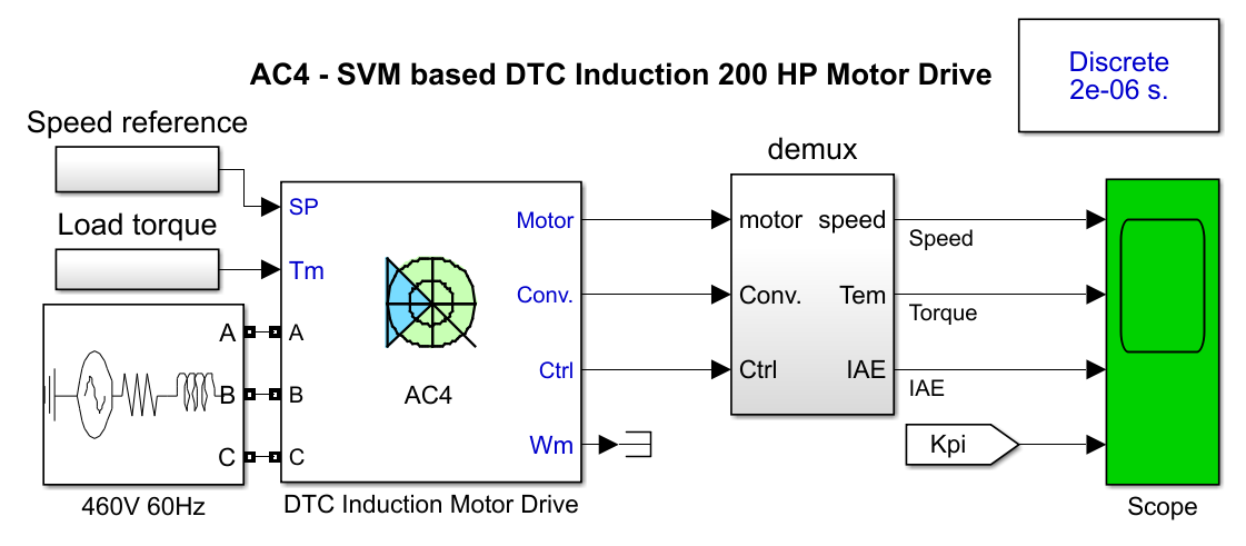
Fig. 3 shows the Simulink model of the IM speed control using DTC. The IM is inside the DTC Induction Motor Drive block. The parameters of the IM used are listed in Table 1. The input is speed references and load torque. The power supply used is AC three phase 460V 60Hz. Whereas simulation output for analysis is speed, torque, IAE, and Kp and Ki gain changes.
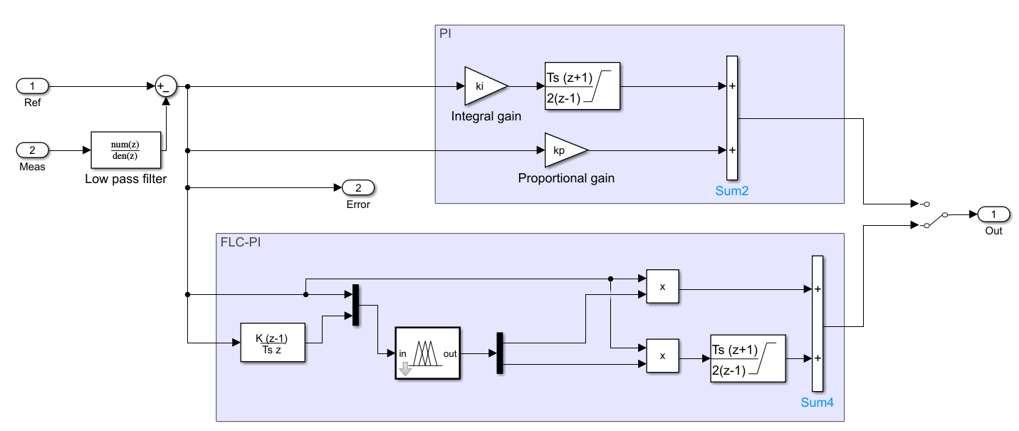
The proposed method block diagram of Simulink is shown in Fig. 4. There are two different control blocks which is PI and FLC-PI which can be selected using the switch in the output. The FLC in FLC-PI is used to vary the Kp and Ki based on the speed error and error changes. The fuzzy rule used for output Kp and Ki is the same and is listed in Table 2. The fuzzy Mamdani type with triangle membership is used in this design.
Parameters | Value |
Power, kVA | 149.2 |
Voltage, Vrms | 460 |
Frequency, Hz | 60 |
Inertia (J), kgm2 | 3.1 |
Friction factor, Nms | 0.08 |
Pole pair | 2 |
E/CE | N | Z | P |
N | M | M | M |
Z | Z | Z | Z |
P | B | B | B |
There are two tests used to prove the performance of the proposed method which are the no-load and loaded test. The tolerance of the speed control is ± 1%. The integral absolute of error (IAE) is used to compare the performance besides settling time and overshoot or undershoot. The IAE value is calculated as accumulative from the beginning until the end of the simulation.
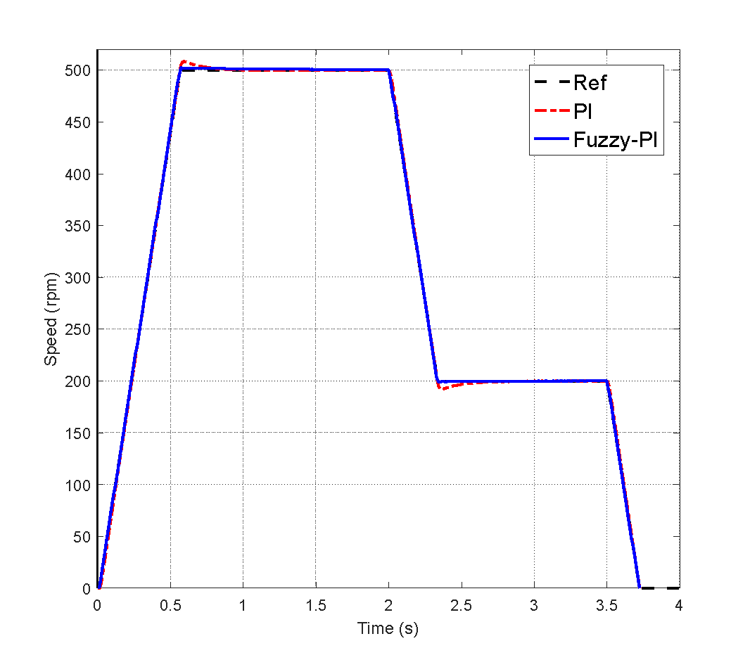
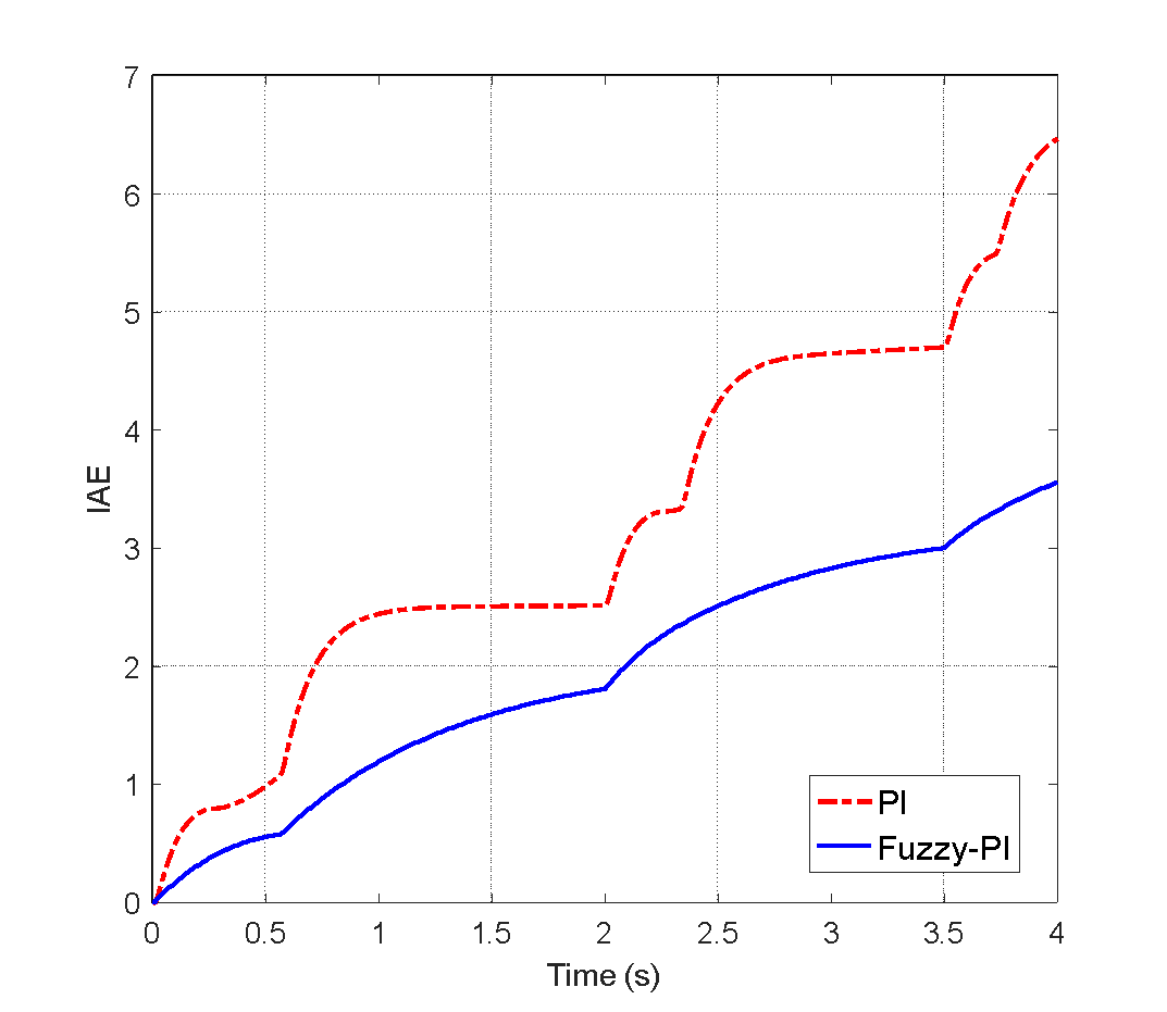
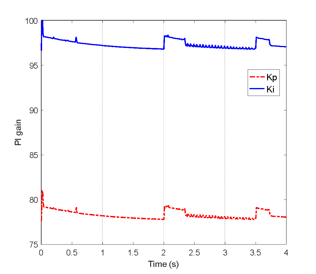
In the no-load test, only speed tracking is performed. There are two set-point speeds used in one cycle which are 500rpm and 200rpm. This represents the increasing and decreasing speed respectively. Fig. 5 shows the no-load test which consists of speed, IAE, and Kp/Ki graph. It can be seen that method can track the speed reference well. However, there are small overshoot and undershoot found in the PI responses. This makes the PI method has higher IAE compared to Fuzzy-PI as shown in Fig. 5(b). Whereas Fig. 5(c) depicts the Kp and Ki of the Fuzzy-PI method which varied based on the error (E) and error changes (CE). It shows that when there are speed changes, both E and CE will have a high value that makes both Kp and Ki increase.
In more detail, the quantitative value of performance parameters is resumed in Table 3. In the first set-point, Fuzzy-PI is superior compared to PI in terms of settling time and overshoot. The proposed method has a faster settled time of 12.31% compared with the PI method. In the second test, the result is identical with Fuzzy-PI being the best. It has a better settling time of 38.18% faster. The settling time of the second set-point is measured from the time simulation of 2s. The minus sign in OS/US means it is an undershoot. In the end, the exact IAE value of Fuzzy-PI and PI is 3.56 and 6.47, respectively. This means the proposed method has better IAE compared to PI by 44.98%. The percentage of IAE may differ if the simulation time is extended.
Control method | Settling time (s) | OS/ US (%) | IAE |
Set-point-1: 500rpm | |||
Fuzzy-PI | 0.57 | < 1 | |
PI | 0.65 | 1.7 | |
Set-point-2: 200rpm | |||
Fuzzy-PI | 0.34 | < -1 | 3.56 |
PI | 0.55 | - 2.4 | 6.47 |
(a)
(b)
(c)
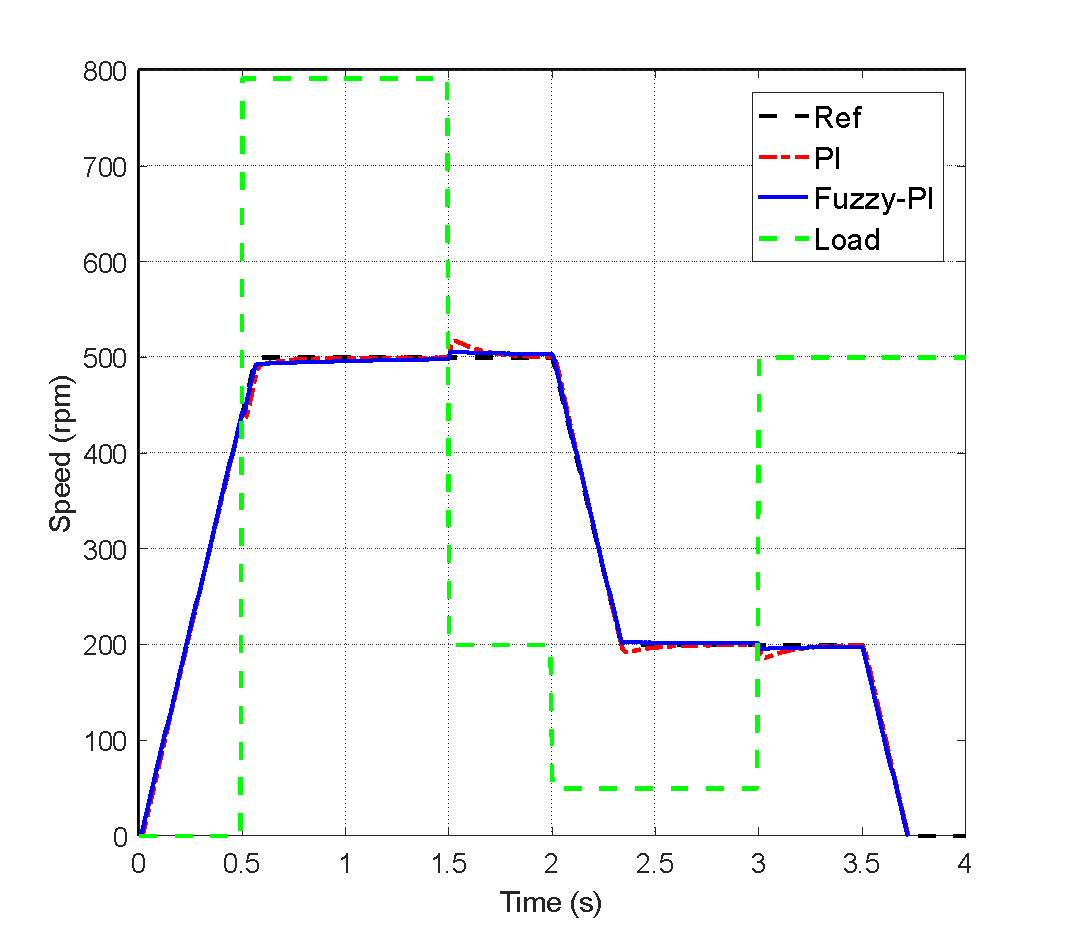
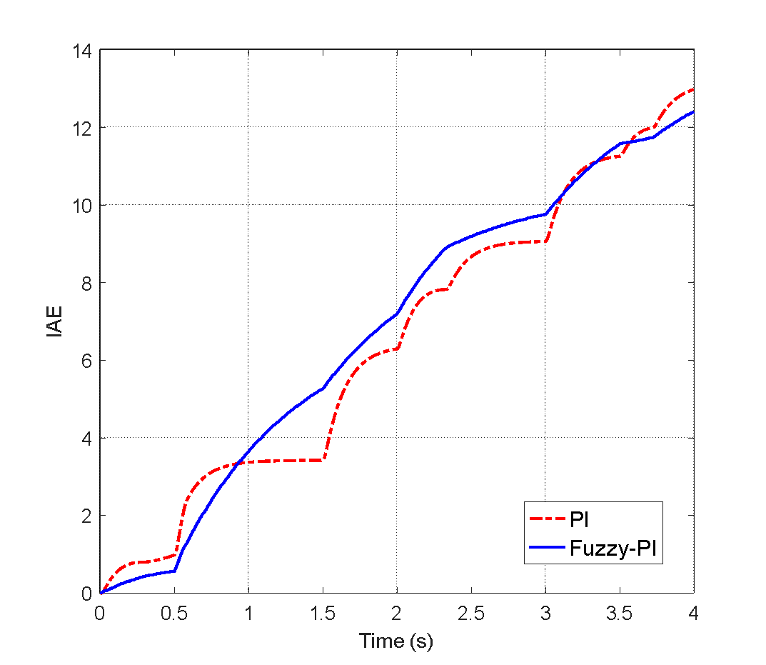
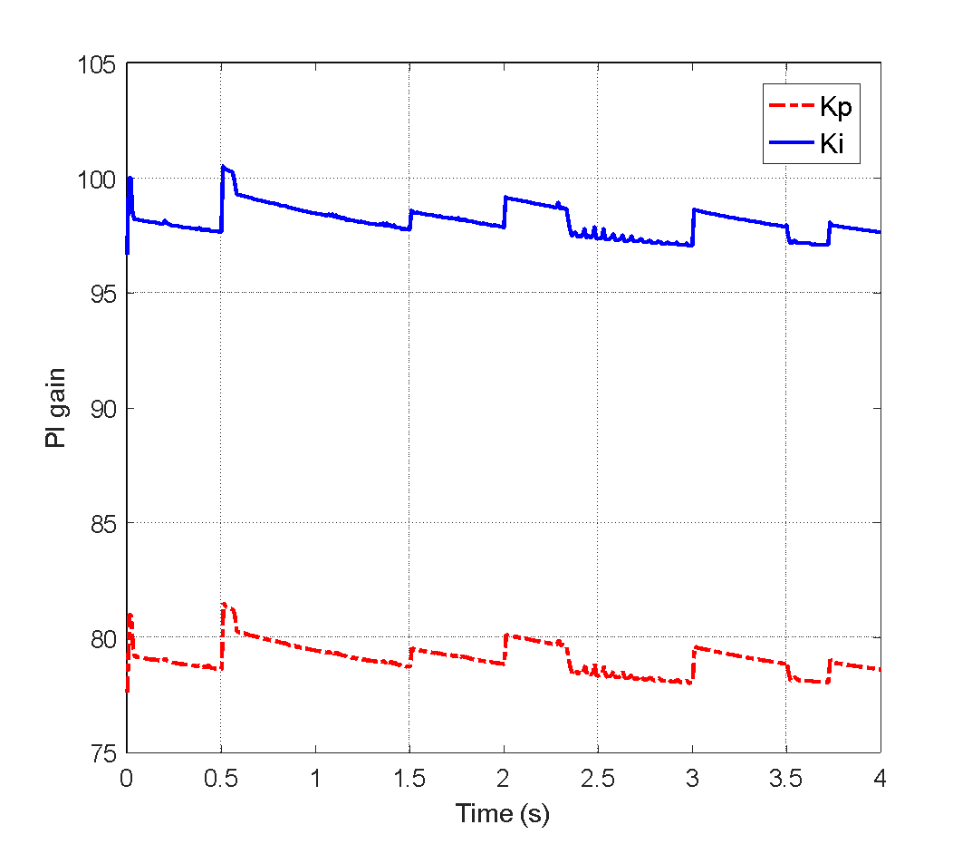
The loaded test is to prove the performance of the speed control when load changes are given. The load is in the form of torque applied to the motor shaft. Fig. 6 shows the loaded test. In terms of speed tracking under loaded conditions, the result is in Fig. 6 (a). It is seen that there is speed fluctuation when the load changes. For example, at time 1.5s, when the load decreases, the speed increases. On the other side, at time 3s when the load increases, the speed decreases. Overall, both control methods can perform speed tracking under loaded conditions well. In terms of IAE, the loaded condition has a higher IAE value. The IAE of PI is nearly close to the Fuzzy-PI one since the load can reduce the overshoot of PI responses. The Kp and Ki value of Fuzzy-PI, it has more variation since the controller wants to maintain the speed under load variation.
The quantitative result of the loaded test is listed in Table 4. In seeing that, in the first set-point, PI is superior to Fuzzy-PI since it is faster to reach the speed references by 37.5%. Whereas in terms of overshoot, the proposed method is still superior to PI. In the second set-point, the proposed method dominated both settling time and undershooting. It is faster by 39.29% than the PI response. The overshoot/undershoot of the loaded test is higher than the no-load test. The last, in terms of IAE, the proposed method is superior with lower IAE compared to the PI method by 4.47%.
Control method | Settling time (s) | OS/ US (%) | IAE |
Set-point-1: 500rpm | |||
Fuzzy-PI | 0.88 | 1.1 | |
PI | 0.64 | 3.49 | |
Set-point-2: 200rpm | |||
Fuzzy-PI | 0.34 | -2.37 | 12.41 |
PI | 0.56 | -6.73 | 12.99 |
The speed control of the induction motor based on DTC has been carried out successfully in the simulation environment. The speed tracking with two conditions, no-load and loaded, the condition was performed. The proposed Fuzzy-PI results are compared to the PI method to identify the improvement. The simulation results prove that the proposed method can perform well in speed tracking and loaded condition. It is superior in terms of settling time, overshoot/ undershoot, and IAE compared to the PI method. It has lower IAE in both speed tracking and loaded conditions by 44.98% and 4.47%, respectively. The fuzzy rules in this study are determined based on experience. In the future, to get the optimal result, the fuzzy rules can be generated from the optimization method.
(a)
(b)
(c)
[1] | H. Maghfiroh, O. Wahyunggoro, A. I. Cahyadi, K. L. Lian, and B. R. Ke, “Speed control of a single Taipei mass rapid transit system train by using a single input fuzzy logic controller,” Int. J. Electr. Comput. Eng., vol. 6, no. 2, pp. 621–629, 2016, https://doi.org/10.11591/ijece.v6i2.8123. |
[2] | H. Maghfiroh, J. S. Saputro, F. Adriyanto, A. Sujono, and R. L. Lambang, “Performance Evaluation of Fuzzy-PID in Speed Control of Three Phase Induction Motor,” IOP Conf. Ser. Mater. Sci. Eng., vol. 1096, no. 1, p. 012071, 2021, https://doi.org/10.1088/1757-899X/1096/1/012071. |
[3] | S. Allirani, V. Jagannathan, “Direct torque control technique in induction motor drives – a review, ” Journal of Theoretical and Applied Information Technology, vol. 60, no. 3, pp. 452-475, 2014, http://www.jatit.org/volumes/sixtyth_3_2014. |
[4] | H. Sarhan, “Efficiency optimization of vector-controlled induction motor drive,” International Journal of Advances in Engineering & Technology, vol. 7, no. 3, pp. 666-674, 2014, https://d1wqtxts1xzle7.cloudfront.net/34120400/3I21-IJAET0721239 |
[5] | M. Demirtas, “DSP-based sliding mode speed control of induction motor using neuro-genetic structure,” Expert Systems with Applications, vol. 36, no. 3, pp. 5533-5540, 2009, https://doi.org/10.1016/j.eswa.2008.06.086. |
[6] | R. Hedjar, P. Boucher, D. Dumur, “Robust nonlinear receding-horizon control of induction motors,” International Journal of Electrical Power & Energy Systems, vol. 46, pp. 353-365, 2013, https://doi.org/10.1016/j.ijepes.2012.10.007. |
[7] | T. Sutikno, N. R. N. Idris, A. Jidin, “A review of direct torque control of induction motors for sustainable reliability and energy efficient drives,” Renewable Sustainable Energy Review, vol. 32, pp. 548-58, 2014, https://doi.org/10.1016/j.rser.2014.01.040. |
[8] | N. E. Ouanjli, A. Derouich, A. E. Ghzizal, S. Motahhir, A. Chebabhi, Y. E. Mourabit, M. Taoussi, “Modern improvement techniques of direct torque control for induction motor drives-a review,” Protection and Control of Modern Power Systems, vol. 4, no. 1, pp. 1-12, 2019, https://doi.org/10.1186/s41601-019-0125-5. |
[9] | A. Alwadie, “A concise review of control techniques for reliable and efficient control of induction motor,” International journal of power electronics and drive systems, vol. 9, no. 3, p. 1124, 2018, http://doi.org/10.11591/ijpeds.v9.i3.pp1124-1139. |
[10] | M. A. Hannan, J. A. Ali, A. Mohamed, A. Hussain, “Optimization techniques to enhance the performance of induction motor drives: A review,” Renewable and Sustainable Energy Reviews, vol. 81, pp. 1611-1626, 2018, https://doi.org/10.1016/j.rser.2017.05.240. |
[11] | A. J. Fattah and I. Abdel-Qader, “Performance and comparison analysis of speed control of induction motors using improved hybrid PID-fuzzy controller,” 2015 IEEE International Conference on Electro/Information Technology (EIT), pp. 575-580, 2015, https://doi.org/10.1109/EIT.2015.7293400. |
[12] | C. K. Lin, “Radial basis function neural network-based adaptive critic control of induction motors,” Applied Soft Computing, vol 11, no. 3, pp. 3066-3074, 2011, https://doi.org/10.1016/j.asoc.2010.12.007. |
[13] | H. Maghfiroh, I. Iftadi, and A. Sujono, “Speed control of induction motor using LQG,” J. Robot. Control, vol. 2, no. 6, pp. 565–570, 2021, https://doi.org/10.18196/jrc.26138. |
[14] | J. Abd Ali, M. A. Hannan, and A. Mohamed, “IMPROVED INDIRECT FIELD-ORIENTED CONTROL OF INDUCTION MOTOR DRIVE BASED PSO ALGORITHM”, Jurnal Teknologi, vol. 78, no. 6-2, 2016, https://doi.org/10.11113/jt.v78.8888. |
[15] | J. A. Ali, M. A. Hannan, A. Mohamed, “Gravitational search algorithm based tuning of a PI speed controller for an induction motor drive,” In IOP Conference Series: Earth and Environmental Science, vol. 32, no. 1, p 012001, 2016, https://doi.org/10.1088/1755-1315/32/1/012001. |
[16] | A. Balestrino, A. Caiti, V. Calabro, E. Crisostomi, and A. Landi, “From Basic to Advanced PI Controllers: A Complexity vs. Performance Comparison,” Advances in PID Control, no. 1, pp. 85-100, 2011, https://doi.org/10.5772/19390. |
[17] | C. Liu and Y. Luo, “Overview of advanced control strategies for electric machines,” in Chinese Journal of Electrical Engineering, vol. 3, no. 2, pp. 53-61, 2017, https://doi.org/10.23919/CJEE.2017.8048412. |
Hari Maghfiroh, Adaptive Fuzzy-PI for Induction Motor Speed Control