Journal of Fuzzy Systems and Control, Vol. 1, No 1, 2023 |
Implementation of Fuzzy Logic Control on a Tower Copter
Fahmizal 1*, Daffa Yanu Kharisma 2, Subuh Pramono 3,4
1,2 Department of Electrical Engineering and Informatics, Vocational College, Universitas Gadjah Mada, Yogyakarta, Indonesia
3 Department of Electrical Engineering, Universitas Sebelas Maret, Surakarta, Indonesia
4 Graduate School of Science and Engineering, Chiba University, Japan
Email: 1 fahmizal@ugm.ac.id, 2 daffa.y@mail.ugm.ac.id, 3 subuhpramono@gmail.com
*Corresponding Author
Abstract — Air transport has become a major attraction for scientists in the last decade, to carry out developments in the fields of firefighting, military, and commercial purposes. A quadcopter is a helicopter with four rotors. There are four arms connected to the main control and each arm has a motor with a rotor. In this study, the position control of a tower control is presented. A Fuzzy Logic Controller (FLC) is proposed, and it performance is compared with PID control. The hardware implementation test shows that FLC is superior to PID. The hardware testing shows that the settling time of the FLC control response is 0.5s while the PID control response is 1.2s. That means FLC settling time is faster by 58.33% compared to PID.
Keywords — tower copter, position control, FLC, PID
In recent years, significant developments have been seen in the field of robotics. Several industries, such as automotive, medical, manufacturing, and Antarctica, use robots as substitutes for workers to avoid dangerous situations. Air transport has become a major attraction for scientists in the last decade, to carry out developments in the fields of firefighting, military, and commercial purposes. While the helicopter itself became the center of attention in the early 20th century. The helicopter was first made using 4 rotors by Debothezat in 1921 or called a quadrotor [1].
A quadcopter is a helicopter with four rotors. There are four arms connected to the main control and each arm has a motor with a rotor. The quadcopter relates to electronic speed control (ESC). ESC is a component that controls the motor speed of the main propulsion [2]. There is a lot of control method for a quadrotor proposed by the researcher. Some of them are PID [3, 4], LQR control [5, 6], sliding mode control (SMC) [7], model predictive control (MPC) [8, 9], and Fuzzy Logic Control (FLC) [10, 11].
A fuzzy logic controller (FLC) is a control method that uses a rule-based that converts linguistic rules into control action [12]. The development of fuzzy logic experienced very rapid development in the field of control techniques, more precisely in non-linear problems and complex calculation problems. The non-linear problems in question are problems that contain elements of uncertainty, imprecise, and noise [13]. Various studies apply fuzzy logic control such as motor control [14], battery charging [15], robotic [16, 17], PV system [18], and energy management of hybrid vehicles [19]. The FLC does not require precise mathematical models of the system [20]. Therefore, it is suitable for quadrotor which has complex mathematical model.
This study implements the tower copter robot by utilizing fuzzy logic control to control the robot's position. The results will be compared to the PID controller to know the improvement achieved by the proposed control method. It is hoped that this simulation can be useful for further research or as a reference for other studies.
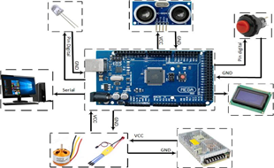
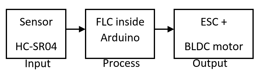
The implementation stage of the tower copter control system uses the driving output in the form of a BLDC motor and the input in the form of the HC-SR04 sensor. The HC-SR04 sensor is a distance sensor based on ultrasonic waves. The tower copter robot work system can be shown in the block diagram of Fig. 1.
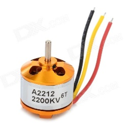
A BLDC motor is a motor that does not use a brush to change the magnetic field but is done electronically. As with direct current permanent magnet (DCMP) motors, BLDC motors have two main parts, namely the rotor and the stator. In a BLDC motor, the rotor is a permanent magnet, and the stator is an electric coil. This motor has a type of rotor, namely the outer rotor and inner rotor, which differs in the location of the rotor on the outside of the stator and vice versa. The working principle of a BLDC motor is the same as that of a DCMP motor, which utilizes the properties of magnets and electromagnetic fields, but in its use to build a quadrotor, BLDC motors are preferred over DCMP motors. This is done because there are several advantages possessed by BLDC motors when compared to DCMP motors such as high efficiency, high torque, and speed, small noise, and volume [21]. The appearance of a brushless motor used is shown in Fig. 2.
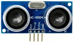
The HC-SR04 is an ultrasonic sensor that has two elements, namely an ultrasonic wave detection element and an ultrasonic wave generator element. Ultrasonic sensors are devices that can detect ultrasonic waves, which are sound waves with ultrasonic frequencies or frequencies that are higher than those that are audible to humans. The HC-SR04 Sensor hardware is shown in Fig. 3.
Prof. Lutfi A. Zadeh, a computer science researcher from California University, first proposed fuzzy logic in 1965 [22]. Professor Zadeh develops a fuzzy logic that can reflect any situation or human mind since he believes that right-false logic (firm logic) cannot capture every human thought. The membership of the items in a set is where assertive logic and fuzzy logic diverge. In strict logic, an element can either be in the set or have a value of one, which indicates that it is true, or it can be out of the set or have a value of zero, which indicates that it is incorrect. In contrast, element membership in fuzzy logic is between 0 and 1.
In this study, Sugeno type fuzzy which has a single value output known as a singleton is used. To obtain fuzzy logic output, 4 stages are needed, including (1) Formation of fuzzy sets (fuzzification). (2) Implication function. The implications used are min, in general, it can be written as in equation (1). (3) Fuzzy rules. In doing fuzzy inference the max (maximum) method is used. In general, it can be written as in equation (2). (4) The defuzzification process uses the center of the area (COA) method. This method is method that is often used in the defuzzification stage. In general, it can be written as in equation (3).
| (1) |
| (2) |
| (3) |
Where:
| : the membership value of error to Xi |
| : the membership value of derror to Xii |
| : membership value of fuzzy solution rule to i |
| : membership value of the fuzzy consequent rule to i |
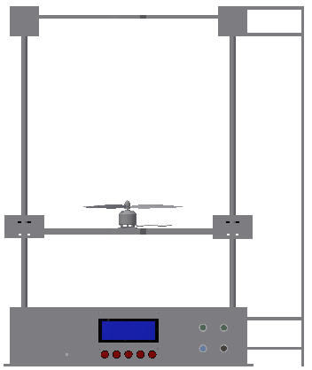
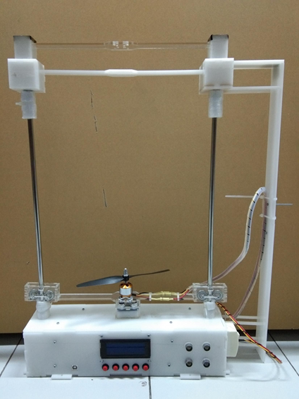
The design of the tower copter in CAD form is presented in Fig. 4. and the finished tower copter is presented in Fig. 5. In the electronic design of the tower copter, consists of a device from the HC-SR04 sensor, a setpoint input module with a push button, the Arduino Uno device, and the BLDC motor as the main driving actuator of the tower copter. Because the tests carried out are static for altitude control, the electricity supply is from the power supply, not the battery. The overall block diagram of the tower copter design electronic system in this study is presented in Fig. 6.
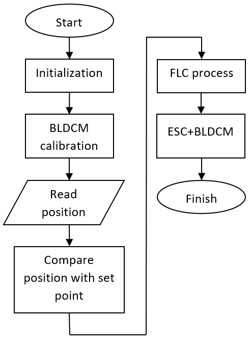
The fuzzy logic implemented in the tower copter control system is embedded in the Arduino Uno with the term embedded fuzzy, meaning that all fuzzy stages are computed on a chip. Fig. 7. is the flow diagram of the fuzzy control system implemented on the tower copter.
The control system workflow starts with the initialization and declaration of variables and constants. Followed by BLDC motor calibration. Then the altitude information from the ultrasonic sensor is processed through a filter so that the readings are more accurate. Altitude readings are compared to a given set point. The difference in the height of the set point and the sensor generates an-error signal which is processed by the FLC. The FLC provides a control signal output to the ESC to control the BLDC motor speed.
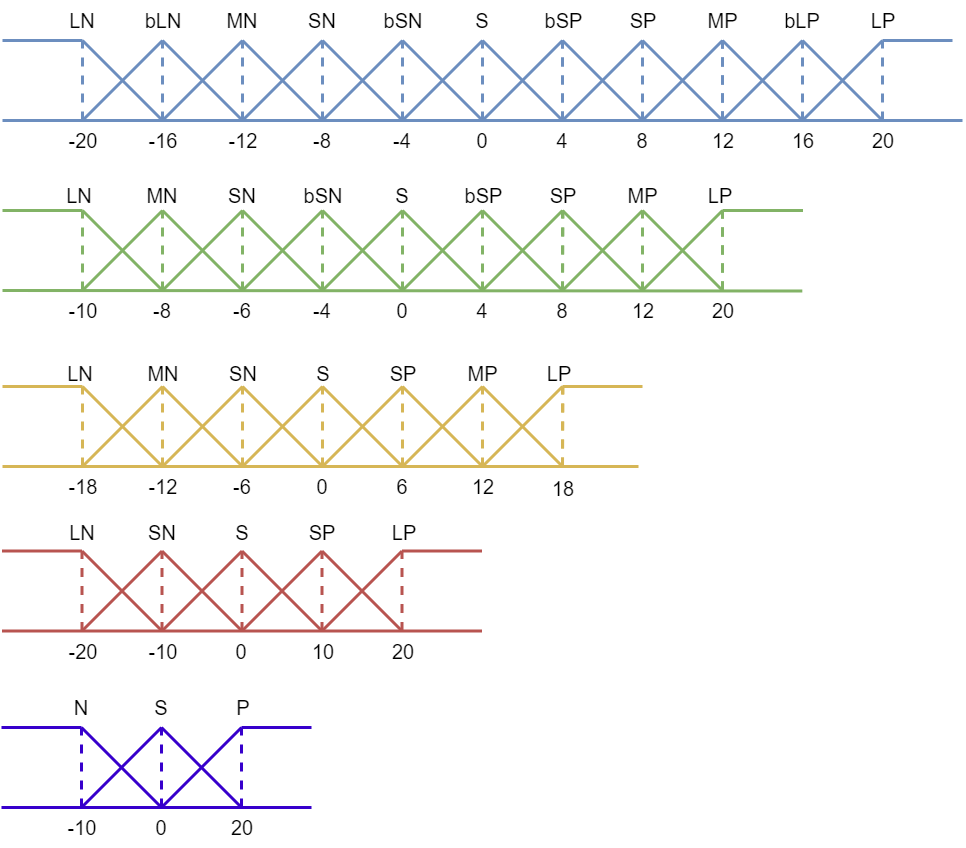
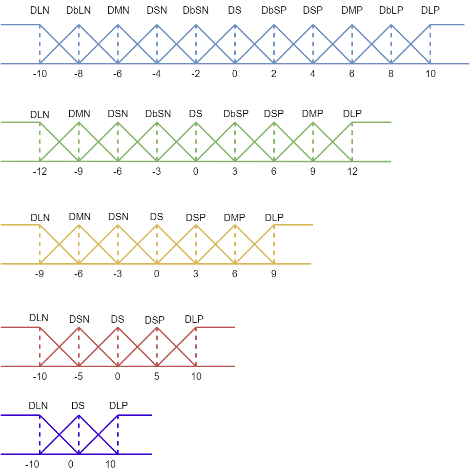
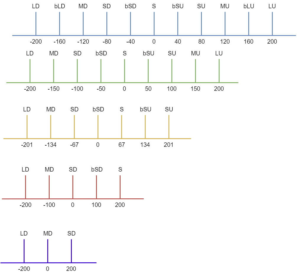
In the testing, the error membership function values have a range of -20 to 20, and the delta error(derror) membership functions with a range of -10 to 10. Whereas the output defuzzification membership function values from -200 to 200. Fig. 8. is a display of the input and output membership functions. Explanation of the membership function as follows: large negative (LN), bit-large negative (bLN), medium negative (MN), small negative (SN), bot-small negative (bSN), zero (S), bit-small positive (bSP), small positive (SP), medium positive (MP), bit-large positive (bLP), large positive (LP). Member with initial D is for derror.
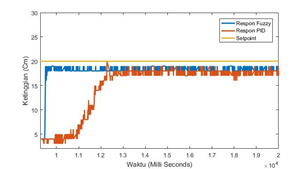
After testing, the results of the graphic response are shown in Fig. 9. Based on the graph, it can be concluded that the fuzzy logic control system is faster than the PID control. This is because the settling time of the fuzzy logic control response is 0.5 seconds while the PID control response reaches 1.2 seconds. That means FLC settling time is faster by 58.33% compared to PID. Video implementation results of this paper [Online] is live at https://youtu.be/I2aUIh_EOaU
LN | bLN | MN | SN | bSN | S | bSP | SP | MP | bLP | LP | |
DLN | LD | LD | bLD | bLD | MD | MD | SD | SD | bSD | bSD | S |
DbLN | LD | bLD | bLD | MD | MD | SD | SD | bSD | bSD | S | bSU |
DMN | bLD | bLD | MD | MD | SD | SD | bSD | bSD | S | bSU | bSU |
DSN | bLD | MD | MD | SD | SD | bSD | bSD | S | bSU | bSU | SU |
DbSN | MD | MD | SD | SD | bSD | bSD | S | bSU | bSU | SU | SU |
DS | MD | SD | SD | bSD | bSD | S | bSU | bSU | SU | SU | MU |
DbSP | SD | SD | bSD | bSD | S | bSU | bSU | SU | SU | MU | MU |
DSP | SD | bSD | bSD | S | bSU | bSU | SU | SU | MU | MU | bLU |
DMP | bSD | bSD | S | bSU | bSU | SU | SU | MU | MU | bLU | bLU |
DbLP | bSD | S | bSU | bSU | SU | SU | MU | MU | bLU | bLU | LU |
DLP | S | bSU | bSU | SU | SU | MU | MU | bLU | bLU | LU | L |
From a series of tests and analyses that have been carried out on the implementation of the fuzzy logic control system on the copter tower, the design of tower copter system has been successfully designed and implemented with a fuzzy logic control system. Based on the graph of the response comparison of fuzzy logic and PID controls, it is found that the fuzzy logic response reaches the setpoint faster and is more stable. FLC settling time is faster by 58.33% compared to PID. When testing for a long time, the tower copter using the ESC 30A will overheat after operating for 20 minutes.
[1] | E. Abbasi, “Development and Implementation of a Adaptive Fuzzy Control System for a VTOL Vehicle in Hovering Mode,” Int. J. Control Theory Comput. Model., vol. 7, no. 1/2, pp. 1–14, 2017, https://doi.org/10.5121/ijctcm.2017.7201. |
[2] | M. B. Hurd, “Control of a quadcopter aerial robot using optic flow sensing,” scholarworks, 2013, http://hdl.handle.net/11714/3256. |
[3] | Li, X., Chen, Y., & Chen, “Quadrotor Tracking Control Based on PID Algorithm,” Computer Measurement and Control, vol. 24, no. 7, pp. 109-112, 2016, https://www.oriprobe.com/journals/jsjzdclykz/2016_7.html |
[4] | F. Rinaldi, A. Gargioli, F. Quagliotti, “PID and LQ regulation of a multirotor attitude: Mathematical modelling, simulations and experimental results,” Journal of Intelligent & Robotic Systems, vol. 73, pp. 33-50, 2014, https://doi.org/10.1007/s10846-013-9911-x. |
[5] | N. K. Tran, E. Bulka and M. Nahon, “Quadrotor control in a wind field,” 2015 International Conference on Unmanned Aircraft Systems (ICUAS), pp. 320-328, 2015, https://doi.org/10.1109/ICUAS.2015.7152306. |
[6] | B. Panomrattanarug, K. Higuchi and F. Mora-Camino, “Attitude control of a quadrotor aircraft using LQR state feedback controller with full order state observer,” The SICE Annual Conference 2013, pp. 2041-2046, 2013, https://ieeexplore.ieee.org/document/6736320. |
[7] | K. Runcharoon and V. Srichatrapimuk, “Sliding Mode Control of quadrotor,” 2013 The International Conference on Technological Advances in Electrical, Electronics and Computer Engineering (TAEECE), pp. 552-557, 2013, https://doi.org/10.1109/TAEECE.2013.6557334. |
[8] | J. Dentler, S. Kannan, M. A. O. Mendez and H. Voos, “A real-time model predictive position control with collision avoidance for commercial low-cost quadrotors,”2016 IEEE Conference on Control Applications (CCA), pp. 519-525, 2016, https://doi.org/10.1109/CCA.2016.7587882. |
[9] | M. Bangura, R. Mahony, “Real-time model predictive control for quadrotors,” IFAC Proceedings Volumes, vol. 47, no. 3, pp. 11773-11780, 2014, https://doi.org/10.3182/20140824-6-ZA-1003.00203. |
[10] | E. Yazid, M. Garratt, F. Santoso, “Position control of a quadcopter drone using evolutionary algorithms-based self-tuning for first-order Takagi–Sugeno–Kang fuzzy logic autopilots,” Applied Soft Computing, vol. 78, pp. 373-392, 2019, https://doi.org/10.1016/j.asoc.2019.02.023. |
[11] | N. M. Raharja, Iswanto, O. Wahyunggoro and A. I. Cahyadi, “Altitude control for quadrotor with mamdani fuzzy model,” 2015 International Conference on Science in Information Technology (ICSITech), pp. 309-314, 2015, https://doi.org/10.1109/ICSITech.2015.7407823. |
[12] | H. Maghfiroh, C. Hermanu, M. H. Ibrahim, M. Anwar, A. Ramelan, “Hybrid fuzzy-PID like optimal control to reduce energy consumption,” TELKOMNIKA (Telecommunication Computing Electronics and Control), vol. 18, no. 4, pp. 2053-2061, 2020, http://doi.org/10.12928/telkomnika.v18i4.14535. |
[13] | A. Saelan, “Logika Fuzzy,” Strukt. Disk., vol. 1, no. 13508029, pp. 1–5, 2009, https://d1wqtxts1xzle7.cloudfront. |
[14] | H. Maghfiroh, O. Wahyunggoro, A. I. Cahyadi, K. L. Lian, B. R. Ke, “Speed Control of a Single Taipei Mass Rapid Transit System Train by Using a Single Input Fuzzy Logic Controller,” International Journal of Electrical and Computer Engineering, vol. 6, no. 2, p. 621, 2016, http://doi.org/10.11591/ijece.v6i2.pp621-629. |
[15] | M. Nizam, H. Maghfiroh, A. Ubaidilah, Inayati, and F. Adriyanto, “Constant current-fuzzy logic algorithm for lithium-ion battery charging,” Int. J. Power Electron. Drive Syst., vol. 13, no. 2, pp. 926–937, 2022, http://doi.org/10.11591/ijpeds.v13.i2.pp926-937. |
[16] | T. Dewi, S. Nurmaini, P. Risma, Y. Oktarina, M. Roriz, “Inverse kinematic analysis of 4 DOF pick and place arm robot manipulator using fuzzy logic controller,” International Journal of Electrical & Computer Engineering, vol. 10, no. 2, pp. 2088-8708, 2020, http://doi.org/10.11591/ijece.v10i2.pp1376-1386. |
[17] | M. Soliman, A. T. Azar, M. A. Saleh, H. H. Ammar, “Path planning control for 3-omni fighting robot using PID and fuzzy logic controller,” The International Conference on Advanced Machine Learning Technologies and Applications (AMLTA2019) 4, vol. 921, pp. 442-452, 2020, https://doi.org/10.1007/978-3-030-14118-9_45. |
[18] | M. Errouha, A. Derouich, S. Motahhir, O. Zamzoum, N. E Ouanjli, A. E. Ghzizal, “Optimization and control of water pumping PV systems using fuzzy logic controller,” Energy Reports, vol. 5, pp. 853-865, 2019, https://doi.org/10.1016/j.egyr.2019.07.001. |
[19] | C. Lin, W. Luo, H. Lan, and C. Hu, “Research on Multi-Objective Compound Energy Management Strategy Based on Fuzzy Control for FCHEV,” Energies, vol. 15, no. 5, p. 1721, 2022, https://doi.org/10.3390/en15051721. |
[20] | M. M. Shaker and Y. M. B. I. Al-khashab, “Design and implementation of fuzzy logic system for DC motor speed control,” 2010 1st International Conference on Energy, Power and Control (EPC-IQ), pp. 123-130, 2010, https://ieeexplore.ieee.org/abstract/document/5767298. |
[21] | M. A. Ibrahim, A. K. Mahmood, and N. S. Sultan, “Optimal PID controller of a brushless DC motor using genetic algorithm,” Int. J. Power Electron. Drive Syst., vol. 10, no. 2, pp. 822–830, 2019, http://doi.org/10.11591/ijpeds.v10.i2.pp822-830. |
[22] | M. M. Gupta, “Forty-five years of fuzzy sets and fuzzy logic-A tribute to Professor Lotfi A. Zadeh (the father of fuzzy logic),” Scientia Iranica, vol. 18, no. 3, p. 685, 2011, https://doi.org/10.1016/j.scient.2011.04.023. |
Fahmizal, Implementation of Fuzzy Logic Control on a Tower Copter