(1)

(2)

(3)

(4)
Journal of Fuzzy Systems and Control, Vol. 2, No 3, 2024 |
An Application of STM32F4-Embedded ANFIS-Fuzzy Controller for Tower Crane
Ngoc-Truong-Son Nguyen 1, Quang-Hai Dang 2, Dang-Khang Nguyen 3, Duc-Quan Lam 4, Vo-Hoai-Nam Nguyen 5,
Nguyen-Phap-Tri Le 6, Nguyen-Khang Tran 7, Van-The-Hieu Bui 8, Thai-Hoa Nguyen 9, Thi-Hong-Lam Le 10,*
1, 2, 3, 4, 5, 6, 10 Faculty of Electrical and Electronics Engineering, Ho Chi Minh City University of Technology and Education (HCMUTE), Vietnam
7, 8, 9 Faculty of International Education, Ho Chi Minh City University of Technology and Education (HCMUTE), Vietnam
Email: 1 19151024@student.hcmute.edu.vn, 2 21145629@student.hcmute.edu.vn, 3 21161324@student.hcmute.edu.vn,
4 21161351@student.hcmute.edu.vn, 5 21145212@student.hcmute.edu.vn, 6 20151070@student.hcmute.edu.vn,
7 19161002@student.hcmute.edu.vn, 8 19161055@student.hcmute.edu.vn, 9 20151276@student.hcmute.edu.vn,
*Corresponding Author
Abstract—In this paper, we examine tower crane – a MIMO under-actuated system- which is popular in both academia and industry. From a successful PID controller for this model, we design a fuzzy controller that is generated by the ANFIS toolbox from MATLAB. The proposed controller is shown to be viable based on both the simulation and experimental results obtained. In experiments, the angle of load vibrates a maximum of 10 degrees around the set angle and the settling error is a maximum of 1 degree. Also, the settling time of the trolley is a maximum of 12 sec. These results are acceptable. This control method controls positions and decreases the fluctuation of this model. In the hardware platform, STM32F4 Discovery is used as a control board, and it is well-embedded by fuzzy blocks to prove its ability in future intelligent control.
Keywords—Tower Crane; STM32F4; Fuzzy Control; ANFIS; MIMO Under-Actuated
In control engineering, standard models, such as pendulous [1] and ball and beam [2], are used to examine control algorithms in laboratories. However, the requirement of researching models which are popular in both academia and industry exists. Therefore, kinds of models, such as cranes [3], anti-vibration model to protect buildings from earthquake [4] are more interested due to their uses in real life. Tower crane is a popular model in construction and transferring goods [5]. It is also a standard model in the control laboratory by the company INTECO. With this standard model, LQR control [6], fuzzy control [7] and sliding mode control [8] are tested well on this experimental model. However, the price of this educational model is high. Thence, self-made real-time models are developed in [9]. In that model, a fuzzy controller is developed from structure of 81-rule fuzzy blocks for two separated SIMO systems. In that research, the control board is DSP TMS320F28335 which is also expensive. Its ability to widen the hardware platform for students is low.
Arduino is a much cheaper and more popular control board than DSP. It is supported by a large community [10]. However, only linear control algorithms, such as PID and LQR can be embedded well to control simple models, such as a ball in the tube [11] or heating oven [12]. If being used to control complex models, such as tower cranes, it cannot be used due to its low-velocity operation. Arduino is not suitable for intelligent control for MIMO under-actuated models, such as tower cranes.
STM32F4 can be MATLAB-embedded to control SIMO systems as a high-order inverted pendulum system in nonlinear and intelligent control [13]. Also, for MIMO under-actuated, in [14], PID control structure is applied well for tower crane in both simulation and experiment. In the experiment, those authors embedded successfully MATLAB/Simulink blocks which imitate the PID structure to control positions and anti-fluctuation well. The control board in that research is still STM32F4, which is much cheaper than DSP TMS320F28335. Actually, to control a black-box or grey-box model, such as a reality complex tower crane, intelligent control is a solution. Therefore, a survey of using fuzzy controllers in embedding for STM32F4 is necessary to prove the ability to develop hybrid controllers and intelligent controllers for this model.
In this study, depending on a former PID control structure in [14], we use the ANFIS toolbox to generate a fuzzy controller. This intelligent controller will be examined in simulation before transferring to an embedded program for the real-time model. We prove that embedded intelligent blocks can be applied well to an experimental model.
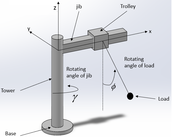
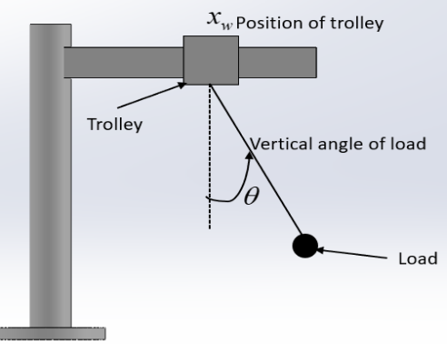
The dynamic equations of a complex real model, such as the crane in the experiment of this paper can be obtained through the identification method as in [15] or using neural networks as in [16] to make simulation close to the experiment. However, the structure of the resistor sensors, which will be presented in the experiment of this paper, makes uncertain noise in signals. Thence, collected data may include noise to make the dynamic equations not exact. Moreover, in this paper, we need to examine the ability of a fuzzy controller on the crane. Thence, if the fuzzy method is good in simulation, it is possible in a real model. The total exactness of the simulation model to a real model can be accepted. A popular and simple mathematical model in [17] of tower cranes can be obtained. In that research, only simulation is shown. However, the dynamic equations are shown adequately in that research. The system parameters, variables, and their values can be referred to in Table 1 and Table 2. The mathematical model can be seen in Fig. 1 and Fig. 2 for considering variables. From [17], dynamic equations of the tower crane are shown in (1)-(4).
| (1) |
| (2) |
| (3) |
| (4) |
where
|
Symbol | Description | Unit |
| Position of trolley | m |
θ | The angle of load by direction of the trolley | rad |
ϕ | Fluctuation angle of load | rad |
γ | Angle of tower | rad |
| The moment that affects the tower | Nm |
| The force which affects the trolley | N |
Symbol | Description | Value | Unit |
m | Mass of load | 0.32 | kg |
g | Gravitational acceleration | 9.8 | m/s2 |
L | Length of string | 0.32 | m |
M | Mass of trolley | 0.7 | kg |
| Coefficient of motor A | 5.58 | NA |
| Coefficient of motor B | 11.91 | NA |
| The voltage applied for motor A | NA | V |
| The voltage applied for motor B | NA | V |
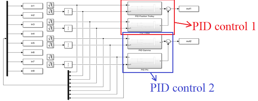
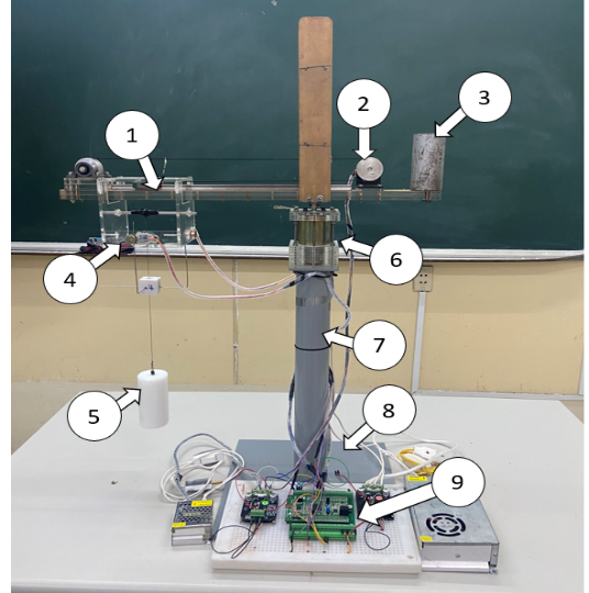
In [17], PID controller is used well. In that research, a structure of two PID blocks is used for controlling x and θ (PID control 1). These variables belong to the trolley and the angle of load following the trolley’s direction. Another structure of two PID blocks is used for controlling ϕ and γ (PID control 2). These variables belong to the tower and the angle of load following the rotating direction of the tower. Thence, four blocks are used in the PID structure in [17]. To create an ANFIS block for controlling the model, a collecting program to obtain input-output data of the PID controller is designed in Fig. 3.
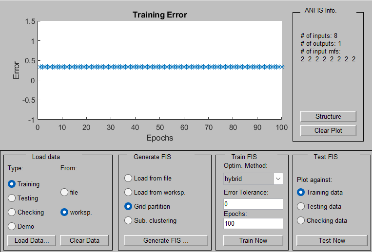
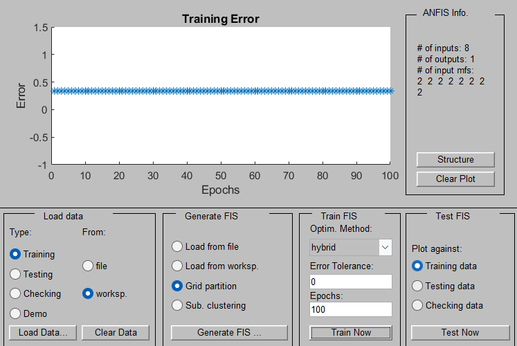
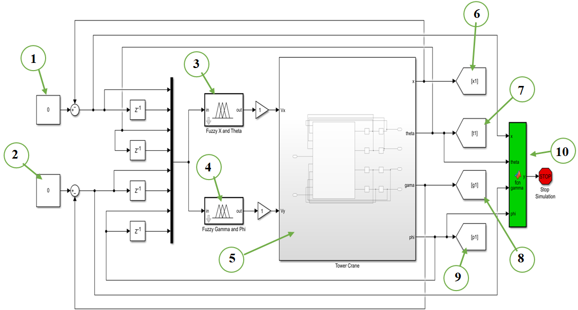
Eight random signals (from input 1 to input 8) are given to inputs of the PID structure. Two outputs (output 1 and output 2) are outputs of the PID controller. The data of these outputs are collected to identify the PID controller. The IDENT toolbox of MATLAB software collects data on inputs and outputs for each PID control and trains fuzzy blocks to imitate each PID control as in Fig. 4 and Fig. 5. After being trained, two fuzzy blocks are obtained. They replace PID controls 1 and 2 from the simulation program from [17]. So, we obtain a new fuzzy-ANFIS control program of simulation in Fig. 6.
Description of blocks in Error! Reference source not found. is listed as,
|
|
The initial values of the system are chosen as
| (5) |
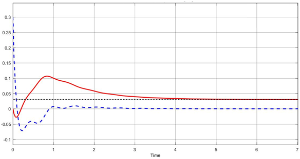
The system is controlled under a fuzzy controller as in Fig. 6. Simulation results are shown in Fig. 7 and Fig. 8. In Fig. 7, the angle of load takes only 2 seconds to be stable. This angle vibrates about 0.07 rad. The trolley needs 4 sec to be exactly at the expected position. The settling error is zero. Fuzzy control 1 (number 3 of Fig. 6) can control the trolley well and the angle of load in the trolley’s direction.
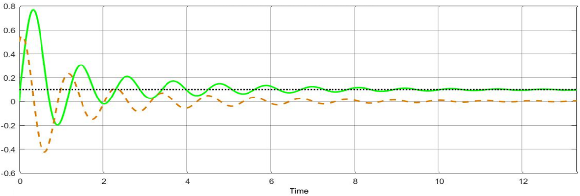
In Fig. 8, angle of load vibrates from -0.4 rad to 0.6 rad and takes 6 sec to be stable. The tower rotates from -0.2 rad to 0.6 rad and takes about 6 sec to be stable at the set point.
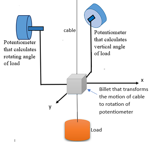
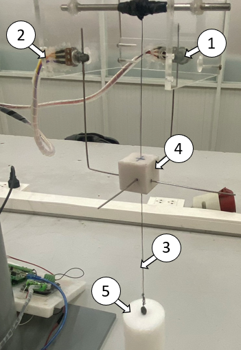
To measure angles of load, a structure of resistors is shown in Fig. 10 and Fig. 11.
Description of components in Fig. 11 is:
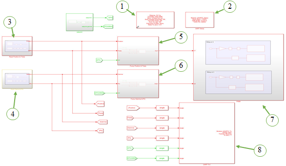
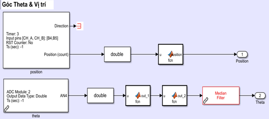
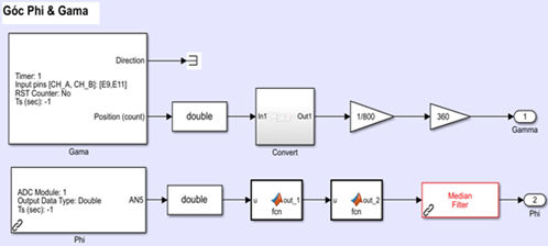
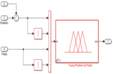
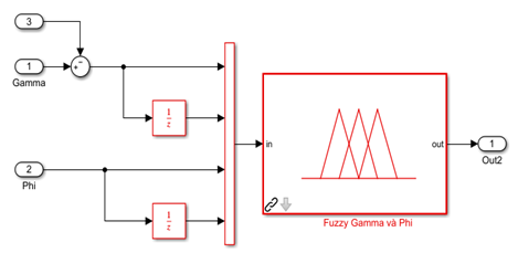
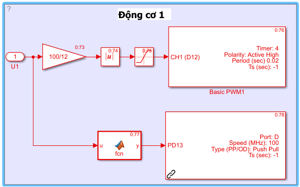
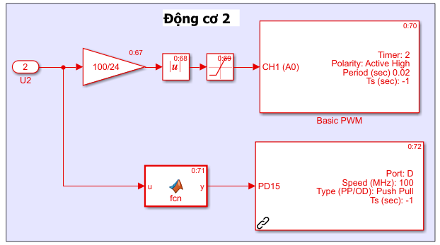
An embedded program to operate the fuzzy-ANFIS controller for the experimental model is shown in Fig. 12.
Description of blocks in Fig. 12 is:
 of tower and angle φ of load. Components inside this block are shown in Fig. 14. of tower and angle φ. Components inside this block are shown in Fig. 16.
In this experiment, the set-point is all zeros. The initial values of the system are selected as
| (6) |
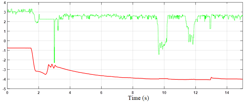
The response of the system is shown in Fig. 19 and Fig. 20. In Fig. 19, the trolley moves from -13 cm to 23 cm before being stable at the 4th second. The settling error of the position of the trolley is 1 cm. The angle of load vibrates from -12 degrees to 1 degree before settling at 3rd second. The settling error is 1 degree. This error is created by the uncertainty of the structure of the sensor in Fig. 10 and Fig. 11. The hole inside the plastic hole is the cause of this error. In order to decrease this error, this hole can be made tighter. However, the so-tight hole will make the motion of the string difficult, and the load is impossible to move.
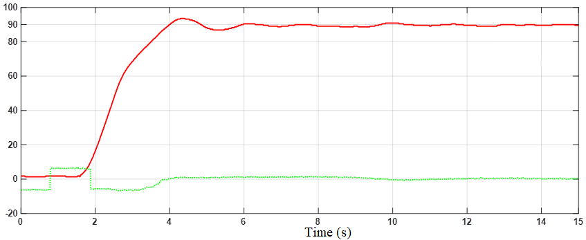
In Fig. 20, tower fluctuates from -3 degrees to 8 degrees. The settling time of motion of the tower is 2 sec. The settling error of this angle is about 1 degree. This settling error is created by the friction force of the tower. This factor is not regarded in dynamic equations from (1)-(4). The angle of load vibrates from -15 degrees to 4 degrees and settles after 2 sec.
When set points are zeros, the trolley, tower, and load terminate the vibration fast, and the initial positions of the tower and trolley are kept well.
The set points are chosen as:
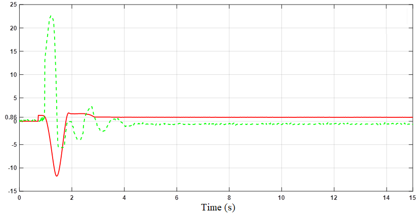
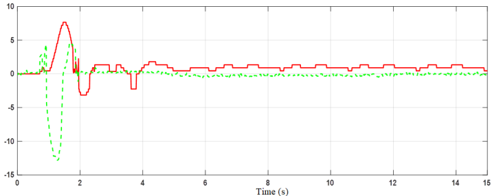
Experimental results are shown in Fig. 21 and Fig. 22.
In Fig. 21, setting time of motion of the trolley is 12s. The vibration of the angle is from -1 degrees to 2 degrees and settling error of nearly 2 degrees. The big settling error is caused by mechanical structure (disadvantages of structure of resistors). Due to the structure of the resistors, the vibration of load by the direction of the trolley is not big and not fluent. However, the survey of the angle of load still describes the features of the system. Besides, the encoder sensor of the trolley works well and the survey of motion of the trolley is good in this case. The signal of motion of the trolley moves fluently and this variable is controlled well
In Fig. 22, the tower needs 4 sec to move to the set-angle. The settling error in this case is nearly zero. Its vibration is small. Also, the vibration of the angle of load terminates just in 4 sec and the settling error is zero. In this case, the vibration of the angle of load through the tower axis is more fluent than the vibration of the angle of load through the trolley’s direction (in Fig. 21). The structure in Fig. 11 supports better the angle of load under the rotation of the tower than under the trolley’s direction. Through this experiment, from Fig. 21 and Fig. 22, when set-points are not zeros, the system still works well under fuzzy –ANFIS controller.
From this research, from a former PID control platform for tower cranes, we utilize the ANFIS toolbox to create a fuzzy control structure. This controller imitates the PID controller to follow the idea that intelligent control learns from the experiences of experts. This controller is proven to control well the position of the trolley and the angle of the tower in both zero set-point and expected non-zero set-point. Moreover, the vibration of the load is terminated through operation. From this study, it is obvious that intelligent control can be utilized for STM32F4 to control the MIMO under-actuated model which is presented by tower crane in this case. Furthermore, this research confirms the ability of the fuzzy control method to imitate the control ability of the expert- PID controller in this case- for MIMO under-actuated models. Also, the tower crane, through this paper, can be a standard model for research and training in laboratories of universities for intelligent control besides linear control. However, the disadvantage of sensor structure (in Fig. 11) is shown due to the vibration of signals. A replacement for this structure is necessary. A solution of using two MPU6050 sensors to measure the angle of each direction can be used in the future.
This paper belongs to the project which is funded by HCMUTE for students of HCMUTE in the year 2025. It is developed from the Bachelor thesis of Mr. Ngoc-Truong-Son Nguyen with the cooperation of Mr. Trung-Dung Nguyen under the supervision of Ms. Eng. Thi-Hong-Lam Le. We also want to give thanks to the PhD. Van-Dong-Hai Nguyen (HCMUTE) in his help in operating this hardware. We, the authors, appreciate this support.
Ngoc-Truong-Son Nguyen, An Application of STM32F4-Embedded ANFIS-Fuzzy Controller for Tower Crane