Journal of Fuzzy Systems and Control, Vol. 1, No 1, 2023 |
|
Mecanum 4 Omni Wheel Directional Robot Design System Using PID Method
Muhamad Alfiyan 1, Riky Dwi Puriyanto 2,*
1, 2 Department of Electrical Engineering, Universitas Ahmad Dahlan, Yogyakarta, Indonesia
Email: 2 rikydp@ee.uad.ac.id
*Corresponding Author
Abstract— Robot or Artificial Intelligence (AI) can be interpreted as a machine with some computer intelligence and controlled by a computer, and has physical abilities like humans. One of the drives of robots that is often used is a DC motor, a DC motor is a motor with an electronic device that converts electrical energy into kinetic energy or motion. However, DC motors often experience a decrease due to the existing load, so that the speed becomes not constant, so it is necessary to design a controller. The controller used is Proportional Integral Derivative (PID). In the PID there are several parameters such as  ,
,  , and
, and  which are selected or determined so that the plant characteristics match the desired criteria. The general parameters are rise-time, settling-time, maximum, overshoot, and steady-state error for a given input. From the results of the DC motor speed control test using the PID method which was carried out by trial and error testing of the four DC motors, the best PID value was obtained with
  ;
;  ;
;  ; and with the Rise Time system message: 14.7452; Overshoots: 0.6667; Settling Time: 52.0100; Undershot: 0; Settling Min: 136; Peaks: 151; Settling Max : 151; and Peak Time: 65.
Keywords—mecanum robot; omni wheel; mecanum wheel; mobile robot.
Introduction
In the current era of technological development that is increasingly developing, especially in developed countries such as Japan, China, Korea, and the United States, it is very dominating for the development of robotics technology. Where this developed country always makes innovations in terms of robot technology [1][2]. Robots are one part of the field of Artificial Intelligence (AI). A robot is defined as a machine with some computer intelligence and controlled by a computer, and has human-like physical abilities [3][4].
Some robots usually output from their movements often using DC motors. DC motor is a motor that is easy to apply. Because of its convenience, at this time DC motors are often used for various purposes, such as industrial and household equipment. However, in its application, the speed of the DC motor often decreases due to the load, so that the speed is not constant so it is necessary to design a controller [5][6] [7][8].
To overcome this, it is necessary to design a DC motor speed control system so that the DC motor can run according to the desired speed. In order for the DC motor speed control system to be better, a controller is needed that can control the system. The controller used to overcome this is with the Proportional Integral Derivative (PID) controller [9][10][11]. The standard configuration of the PID controller has parameters , , and selected or determined so that the plant characteristics match the desired criteria. Common parameters in the design are rise-time, settling-time, maximum, overshoot, and error steady state against the given input [6][5].
There are various kinds and shapes and functions of robots that have been created, and also with a combination in the form of arms or wheels. In wheeled robots that use ordinary wheels, the directional movement of the robot is very limited so that it becomes an obstacle in the robot's function that requires maneuvering in various directions. However, by using omni-wheel and mecanum wheels, the direction of movement of the robot becomes unlimited and can maneuver in all directions [12][13][14].
Omni wheel or often interpreted as Omni Directional Wheel Mobile Robot (OMR) is a wheel consisting of a single wheel and around the core wheel there is an additional wheel [15][16][17][18]. The Mecanum wheel consists of small rollers mounted at a certain angle around a circular hub, using this construction it gives two degrees of freedom for the wheel to move in two perpendicular directions and increases maneuverability, this mecanum wheel itself has formed an angle of 45 degrees [19][20][21][22]. This also encourages researchers to participate in developing robot technology in Indonesia, taking the research title Mecanum 4 Omni Wheel Directional Robot Design System using the PID Method.
Research methods
In this study, the manufacture and design of a robot system with a mecanum chassis was carried out, using four driving wheels using omni-wheel wheels which can later navigate in all directions according to predetermined movements. The most important component in this study is the mecanum robot chassis. A DC motor is a motor with electronic devices that converts electrical energy into kinetic or motion energy. Depending on the name, DC motors are often also called DC motors. DC motors have two terminals and require direct current or direct voltage (direct current) to operate. Where later this DC motor will be used as a crust from a mecanum robot that is directly connected to the omni wheel or mecanum wheel, L298N driver motor, arduino mega 5260. Arduino Mega 2560 is a microcontroller used on the robot, this Arduino board uses the ATmega 2560 Microcontroller IC. The board has more I/O pins, 54 digital inputs/outputs, 15 of which can be used as PWM outputs, 16 input analog, and 4 UART [23], a built-in rotary encoder, and a battery as the power supply of the robot.
System Block Diagram Design
The design of the system block diagram broadly consists of three main parts including input, process, and output. In the input section itself there are six pushbuttons, the pushbutton has the characteristic that when there is no pressing, it is in a disconnected state (off) while when pressed it will be connected (on). Where each pushbutton has a different function, in this input there is also a rotary encoder sensor that functions to calculate the rotation of the DC motor used. For the controller section, it uses the Arduino Mega 2560 microcontroller which has quite a lot of input and output pins as shown in Fig. 1.
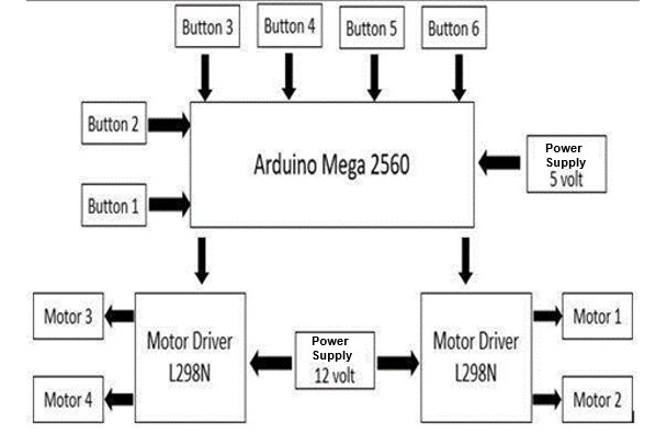
- System Block Diagram
Flowchart
A flowchart is a diagram that reveals the flow of a processing program that is related to processing (instruction) and other processing that usually uses certain symbols. In the flow chart to determine an input of a condition is obtained from experiments carried out when taking a test as shown in Fig. 2.

- Flowchart
Fig. 2 is a drawing of the flow chart in the tests that have been carried out, where this flowchart has six pushbutton inputs. Each pushbutton has a different function, if the input process has been obtained, then it will continue to the conditioning process where there are two conditions, namely the condition (Yes) it will continue, and if it is in the condition (No) it will return to the initial input condition.
From the conditioning process that has been carried out, if the conditions that are met are (Yes) then continue to the process of entering from the angular velocity of the four DC motors, then continue to calculate the error value from the four DC motors, then re-enter the PID calculation of the four DC motors, then process it again in the form of PWM values from each to the four DC motors and then produce output in the form of forward movement in line with the command on pushbutton one.
Likewise, with the other pushbuttons, pushbutton two functions for robots of reverse motion, pushbutton three functions for robots of motion in the right direction, pushbutton four functions for robots of movement in the left side, pushbutton five functions for robots of sliding motion to the right and the last one, namely pushbutton six, functions for robots of sliding motion to the left. Furthermore, if the output of the pushbutton has been fulfilled all the way then the continuation enters the condition that the motor turns off or stops.
Robot Design 3D Design
This robot design system uses Solidwork software. Solidwork software is software that is able to create 3D image designs which will later become a reference before making designs in real or real.
In this design, there are several main components that will later be used for the implementation of the robot manufacture, these components include the L298N motor driver, omni wheel wheels, batteries, DC motors, arduino mega 2560, frames, spacers, and connectors. With a 3D image of the robot as in Fig. 3. Component and function show in Table I.

- Robot 3D design
- Component and FUNCTION
No | Name | Function |
1 | Driver Motor L298N | Used to adjust the directional rotation of DC motors |
2 | Roda Omni Wheel | Used for propulsion from robots |
3 | Battery | Used for power supply or robotic voltage sources |
4 | Motor DC JGA 25-370 | Used for actuators or outputs of robotic programs |
5 | Arduino Mega 2560 | Used as a robotic microcontroller |
6 | First Frame | Used to place electrical components |
7 | Second Frame | Used for battery compartments |
8 | Spacer | Used as a space or pole separating the robot frame |
9 | Connector | Connecting between DC motor and Omni Wheel |
Result and Discussion
In this study, a test was carried out to find out the results of the movement of the robot that had been made in this test, so that various ways of testing the robot were carried out thoroughly. The test is carried out to find out whether the system is working properly. In the first test stage, it is to test the PID control system of each DC motor used using different , , constant values, according to the characteristics of each DC motor. Then the next stage is the second test by comparing the rpm value test that comes out of the serial monitor with the rpm value that has been inputted in the program, then it can be analyzed whether there is a difference or not in the resulting rpm value.
Then in the third test, namely testing the PWM value on each DC motor, this test is carried out in order to get the PWM value that matches what we want. Furthermore, in the fourth test by testing the movement of the robot by moving to a predetermined point and then observing the results of the movement of the robot, whether it has moved in line with what was ordered or not. The following are the results of the discussion on the tests that have been carried out.
Testing of the PID control system of each DC motor used
This test aims to determine the value of the PID control system that corresponds to a DC motor with different characteristics. With the following test results.
Testing of PID control system on motor 1
Testing of the control system using a PID controller with a parameter value of  ; ; ; varied to get a good chart. In the PWM test used, it is 255 or PWM max, with Rise Time: 15.9640; Settling Time: 49.0100; Settling Min: 137; Settling Max: 152; Overshoot: 1.3333; Undershoot: 0; Peak: 151; and Peak Time: 77; then a simulation graph is obtained as in Fig. 4.

- Graph simulation PID motor 1 with PWM 255
Testing of PID control systems on motors 2
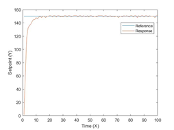
Testing of the control system using a PID controller with a parameter value of ; ; ; varied to get a good chart. In the test the rpm used is 255 or max rpm, with Rise Time: 14.7452; Settling Time: 52.0100; Settling Min: 136; Settling Max: 151; Overshoot: 0.6667; Undershoot: 0; Peak: 151; and Peak Time: 65; then a simulation graph is obtained as shown in Fig. 5.

- Graph simulation PID motor 2 with PWM 255
Testing of PID control system on motor 3
Testing the control system using a PID controller with a parameter value of ;  ; ; varied to get a good chart. In the rpm test used, it is 255 or PWM max, with Rise Time: 6.8135; Settling Time: 25.0100; Settling Min: 136; Settling Max: 151; Overshoot: 0.6667; Undershoot: 0; Peak: 151; and Peak Time: 34; then a simulation graph is obtained as in Fig. 6.
- Graph simulation PID motor 3 with PWM 255
Testing of PID control system on motor 4
Testing the control system using the PID controller, with the parameter value ; ; ; varied to get a good chart. In the PWM test used, it is 255 or PWM max, with Rise Time: 8.2889; Settling Time: 18.0200; Settling Min: 137; Settling Max: 151; Overshoot: 0.6667; Undershoot: 0; Peak: 151; and Peak Time: 31; then a simulation graph is obtained as in Fig. 7.

- Graph simulation PID motor 4 with PWM 255
Fig. 8 is a view of the four graphs of a simulated PID control system with different constant values.
- PID control system simulation graph
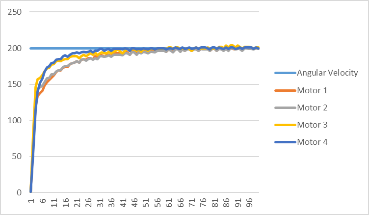
Testing with set-point 200 on motors 1, 2, 3 and 4
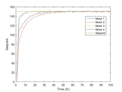
From the next test is the test with a setpoint value setting of 200, using the value ; ; ; as in the second test, namely in Fig. 4 with a near-perfect graph. The results of the PID control system applied to the motor can be seen in Table II which is the result of the PID control system of each motor using the same control system values. A graph of the test results of the four motors can be seen in Fig. 9.
- PID Control Test Results with Set-Point 200, ; ;

The following are the test charts of the four motors that have been carried out;

- Test graph results with set-point = 200, KP = 0.6; KI = 0.1; KD = 0.1
PWM testing on DC motors
The next test is a test by determining the different PWM values on each DC motor. In this test, four tests were carried out, namely with PWM values of 50, 100, 200, and 255. In this test, the DC motor uses a power supply of 12 volts with a minimum PWM value of 40 and a maximum value of 255, and if the PMW value is below 40, the DC motor cannot rotate just buzzing. However, if the PWM value given is more than 40, the greater the angular velocity generated from the DC motor.
Testing of DC motors with PWM 50
In the first test, it was testing from four DC motors using a PWM value of 50, using a power supply of 12 volts. We can observe in Fig. 10. From the tests that have been carried out using a PWM value of 50 and with a maximum angular velocity of 200, the graph on motor one begins to rise after entering the 11th time which previously started from zero, then constant at a value of 100 to the end.
- DC motor test chart results with PWM 50
Testing of DC motors with PWM 100
In the second test, namely testing of the DC motor valve using a PWM value of 100, using a power supply of 12 volts. From the tests that have been carried out using a PWM value of 100 and with a maximum angular velocity of 200, the graph displayed on motor one begins to rise after entering the 11th time which previously started from zero, then constant on the PWM value of 170 to the end. DC motor test chart results with PWM 100 show in Fig. 11.

- DC motor test chart results with PWM 100
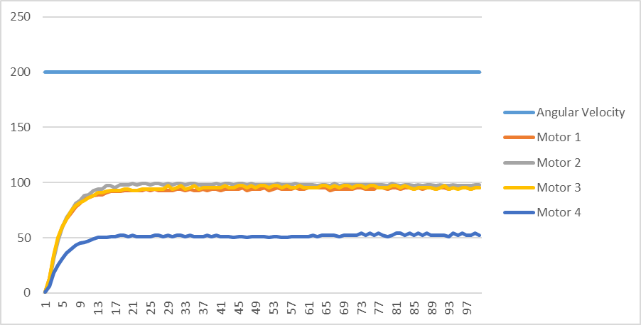
Testing of DC motors with PWM 200
In the third test, namely testing from the DC motor valve using a PWM value of 200, using a power supply of 12 volts. From the tests that have been carried out using a PWM value of 200 and with a maximum angular velocity of 200. The graphs shown on motor 1 and motor 2 experience a slight equation at the time of the initial surge, which is then constant at an angular velocity of 200. As for motor 3 and motor 4 also experience the same initial surge which is then constant also at an angular speed of 200. The following is a display of the test results at the PWM value of 200 as shown in Fig. 12.
- DC motor test chart results with PWM 200
Testing of DC motors with PWM 255
In the fourth test, it was tested from a DC motor using a PWM value of 255, using a power supply of 12 volts. From the tests that have been carried out using a PWM value of 255 and with a maximum angular velocity of 200. The graphs displayed on motor 1 and motor 2 also experience a slight equation as in the PWM 200 test, which is then constant at an angular velocity of 200. As for motor 3 and motor 4 also experience the same initial surge which is constant at an angular velocity of 200 as well. The following is a display of the test results at the PWM value of 200 as shown in Fig. 13.

- Testing of DC motors with PWM 255
Comparative testing of robot movements using omni wheel and mecanum wheel
This study was conducted to find out how the mecanum 4 omni wheel directional robot design system works. So that a thorough test was carried out on the robot. The test is carried out to find out whether the system is working properly. The test carried out is testing the movement of the robot by moving to a predetermined point and then observing the results of the movement whether it has moved well with the accuracy of the position that has a slight error or there is a difference in distance from the desired one. In this test, a comparison of the use of omni wheel and mecanum wheel was also carried out, where both have different wheel shape characteristics.
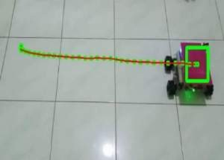
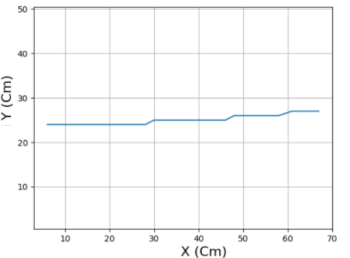
Forward motion testing using omni wheel
In the forward motion test using the omni wheel, tracking results were obtained and
plotting as in Fig. 14.

| 
|
(a) | (b) |
- The result of advanced movement tracking (a) The result of plotting forward movement (b)
From the results of the test of the error plotting value that has been carried out as in Fig. 14, it was found that the robot can move forward with a distance of 35cm then the robot experiences a change in the direction of motion until the robot stops.
Reverse motion testing using omni wheel
In the reverse motion test using the omni wheel, tracking results were obtained and plotting as in Fig. 15.

| 
|
(a) | (b) |
- The result of tracking the backward movement (a) The result of plotting the backward movement (b)
From the results of the test of the error plotting value that has been carried out as in Fig. 15, it is obtained that the robot can move backwards with many slips, but the movement of the robot is still on a straight line axis, with a plotting error of 5 cm.
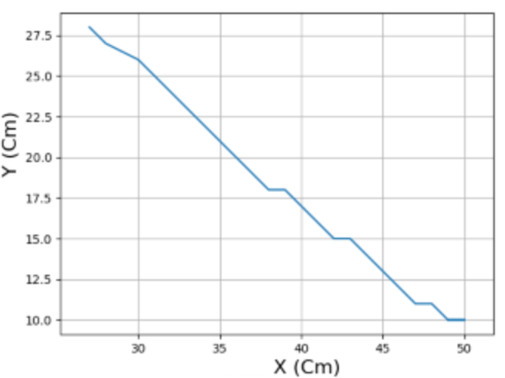
Testing oblique to the right using omni wheel
In the test to the right using the omni wheel, tracking and plotting results were obtained as shown in Fig. 16.

| 
|
(a) | (b) |
- The result of tracking oblique to the right (a) The result of plotting obliquely to the right (b)
From the results of the test of the error plotting value that has been carried out as in Fig. 16, the results were obtained that the robot can move obliquely to the right, by forming an angular arch of 45 degrees, but the oblique to the right in this test still uses omni wheel wheels which results in less than optimal movement. This happens because the omni wheel on the small wheel does not form a 45-degree angle.
Left-to-left cross-wheel testing using omni wheel
In the test to the left using the omni wheel, tracking and plotting results were obtained as shown in Fig. 17.

| 
|
(a) | (b) |
- The result of tracking oblique to the left (a) The result of plotting oblique to the left (b)
From the results of the test of the error plotting value that has been carried out as in Fig. 17, the results were obtained that the robot can move obliquely to the left, by forming an angular arch of 45 degrees, but the left oblique in this test still uses an omni wheel which results in less than optimal movement. This happens because the omni wheel on the small wheel does not form a 45-degree angle.
Swipe right and slide left testing using omni wheel
In the test, sliding right and sliding left the robot experienced problems where the robot could not move the wheels used using omni wheels. Likewise with the chassis used, namely the mecanum chassis, where this chassis on each of the driving wheels does not form a 45-degree angle.
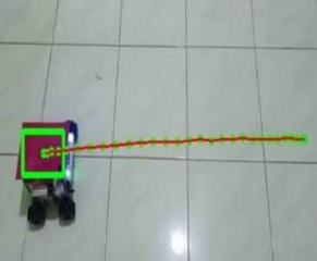
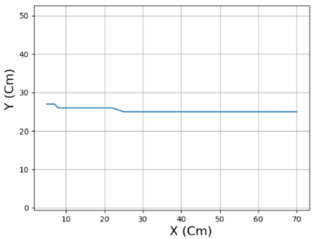
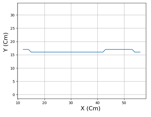
Forward motion testing using mecanum wheels
In the forward motion test using the mecanum wheel, tracking and plotting results were obtained as shown in Fig. 18.
| 
|
(a) | (b) |
- The result of advanced movement tracking (a) The result of plotting forward movement (b)
From the results of testing the value of the plotting error that has been carried out as in Fig. 18, the robot experienced an error of 3 cm, the error occurred after the robot traveled a distance of 55 cm which then resulted in a slight change at the end of the movement.
Backward motion testing using mecanum wheels
In the reverse motion test using the mecanum wheel, tracking and plotting results were obtained as shown in Fig. 19.

| 
|
(a) | (b) |
- The result of tracking the backward movement (a) The result of plotting the backward movement (b)
From the results of testing the value of the plotting error that has been carried out as shown in Fig. 19. Robot experienced an error of 4 cm, there was a change in direction after the robot traveled a distance 30 cm. Which resulted in at the end of the movement slightly changed.
Right-tilted test using mecanum wheelkan roda mecanum
In the test to the right using the mecanum wheel, tracking and plotting results were obtained as shown in Fig. 20.

| 
|
(a) | (b) |
- The result of tracking oblique to the right (a ) The result of plotting obliquely to the right (b)
From the test results of the error plotting value that has been done as shown in Fig. 20, the robot experienced a slight error when testing to the right. However, the movement of the robot is still a straight line with its axis, as well as the direction of the face of the robot is still the same as in the initial position of the test, different when compared to the previous test which used omni wheel wheels.
Left-to-left cross-wheel testing using mecanum wheel
In the test to the left using the mecanum wheel, tracking and plotting results were obtained as shown in Fig. 21.

| 
|
(a) | (b) |
- Figure 21. The result of tracking oblique to the left (a) The result of plotting oblique to the left (b)
From the test results of the error plotting value that has been carried out as shown in Fig. 21, the robot also still experienced a slight error when testing to the left. However, the movement of the robot is still a straight line with its axis, this test is also almost the same in the previous right-hand test. For the direction of the face of the robot itself, it is still the same as in the initial position of the test.
Sliding test to the right using the mecanum wheel
In the test of sliding to the left using the mecanum wheel, tracking and plotting results were obtained as shown in Fig. 22.
| 
|
(a) | (b) |
- Sliding right tracking results (a) Sliding right plotting results (b)
From the test results of the error plotting value that has been done as shown in Fig. 22, the robot still experienced a slight error when testing to slide left. At the beginning of the test, the sliding to the left of the robot slightly slipped so that the robot moved not straight, but at a distance of 20 cm, the robot moved straight again. The result is that the robot cannot slide left perfectly, but in this test it is quite good when compared to tests that use omni-wheel wheels.
Sliding test to the left using the mecanum wheel
In the test of sliding to the left using the mecanum wheel, tracking and plotting results were obtained as shown in Fig. 23.

| 
|
(a) | (b) |
- Sliding left tracking results (a ) Sliding left (b) plotting results
From the test results of the error plotting value that has been done as shown in Fig. 23, the robot still experienced a slight error when testing to slide left. At the beginning of the test, the sliding to the left of the robot slightly slipped so that the robot moved not straight, but at a distance of 20 cm, the robot moved straight again. The result is that the robot cannot slide left perfectly, but in this test it is quite good when compared to tests that use omni-wheel wheels.
Conclusion
Conclusions based on the results of tests conducted on this study. From the results of the DC motor speed control test using the PID method. By trial and error testing or trial and error from the four DC motors, the best PID value was obtained, namely with ; ; ; and with system response Rise Time: 14.7452, Overshoot: 0.6667; Settling Time: 52.0100, Undershoot: 0; Settling Min: 136; Peak: 151, Settling Max: 151; and Peak Time: 65.2.
From the results of movement testing using omni wheel wheels are still constrained by the movement of the oblique to the right and the oblique to the left which is still not optimal, and the test of sliding right and sliding left, the robot cannot navigate properly.
From the results of testing the movement of robots using mecanum wheels, the robot can navigate well, with testing on the oblique to the right and oblique to the left, the robot can move by forming a 45-degree angle perfectly and with the robot's unchanged direction. Likewise, with testing the movement to the right and the movement to the left, the robot can already navigate well.
References
[1] | A. Mukherjee, S. Misra, and N. S. Raghuwanshi, “A survey of unmanned aerial sensing solutions in precision agriculture,” Journal of Network and Computer Applications, vol. 148, p. 102461, 2019, https://doi.org/10.1016/j.jnca.2019.102461. |
[2] | T. P. Tunggal, L. A. Kirana, A. Z. Arfianto, E. T. Helmy, and F. Waseel, “The design of tachometer contact and non-contact using microcontroller,” Journal of Robotics and Control (JRC), vol. 1, no. 3, pp. 65-69, 2020, https://doi.org/10.18196/jrc.1315. |
[3] | C. Ye, Y. Du, S. Yu, Q. Zhao, and C. Jiang, “Design and performance analysis of an adaptive omnidirectional wheel for heavy payload robot,” Industrial Robot: the international journal of robotics research and application, vol. 49, no. 6, pp. 1144-1155, 2022, https://doi.org/10.1108/IR-01-2022-0024. |
[4] | Nitika, S. Kumari, V. Kumar and R. K. Behera, "Solar Powered Smart Home Design with IoT," 2020 IEEE-HYDCON, pp. 1-8, 2020, https://doi.org/10.1109/HYDCON48903.2020.9242901. |
[5] | J. Agarwal, G. Parmar, R. Gupta, and A. Sikander, “Analysis of grey wolf optimizer based fractional order PID controller in speed control of DC motor,” Microsystem Technologies, vol. 24, no. 12, pp. 4997-5006, 2018, https://doi.org/10.1007/s00542-018-3920-4. |
[6] | S. Ekinci, B. Hekimoğlu, and D. Izci, “Opposition based Henry gas solubility optimization as a novel algorithm for PID control of DC motor,” Engineering Science and Technology, an International Journal, vol. 24, no. 2, pp. 331-342, 2021, https://doi.org/10.1016/j.jestch.2020.08.011. |
[7] | M. Khairudin, Efendi, N. Purwatiningsih, and W. Irawan, “The implementation of silicon controlled rectifiers for DC motor control,” In AIP Conference Proceedings AIP Publishing LLC, vol. 1977, no. 1, p. 030035, 2018, https://doi.org/10.1063/1.5042955. |
[8] | Q. I. Fatimah, R. Marselino, and A. Asnil, “Web-Based DC Motor Speed Design and Control,” Motiv. J. Mech. Electr. Ind. Eng., vol. 3, no. 3, pp. 101–112, 2021, https://doi.org/10.46574/motivection.v3i3.99. |
[9] | M. Soliman, A. T. Azar, M. A. Saleh, and H. H. Ammar, “Path planning control for 3-omni fighting robot using PID and fuzzy logic controller,” In International Conference on Advanced Machine Learning Technologies and Applications, Springer, pp. 442-452, 2019, https://doi.org/10.1007/978-3-030-14118-9_45. |
[10] | J. Xu, et al., “Learning to fly: computational controller design for hybrid uavs with reinforcement learning,” ACM Transactions on Graphics (TOG), vol. 38, no. 4, pp. 1-12, 2019, https://doi.org/10.1145/3306346.3322940 . |
[11] | R. P. Borase, D. K. Maghade, S. Y. Sondkar, and S. N. Pawar, “A review of PID control, tuning methods and applications,” International Journal of Dynamics and Control, vol. 9, no. 2, pp. 818-827, 2021, https://doi.org/10.1007/s40435-020-00665-4. |
[12] | J. O. E. S. Keek, S. E. R. L. E. E. Loh, S. H. Chong, and S. Member, “Comprehensive Development and Control of a Path-Trackable Mecanum-Wheeled Robot,” IEEE Access, vol. 7, pp. 18368–18381, 2019, https://doi.org/10.1109/ACCESS.2019.2897013. |
[13] | X. Xu, Z. Wang and C. Feng, "Projector-Guided Non-Holonomic Mobile 3D Printing," 2021 IEEE International Conference on Robotics and Automation (ICRA), pp. 8039-8045, 2021, https://doi.org/10.1109/ICRA48506.2021.9561719. |
[14] | A. Bagade, A. Kulkarni, P. Nangare, P. Shinde, and S. Gudadhe, “Robotic Assistant for Medicine and Food Delivery in Healthcare,” In Cyber Security, Privacy and Networking, Springer, pp. 49-59, 2022, https://doi.org/10.1007/978-981-16-8664-1_5. |
[15] | L. Qiang, W. Heng, L. Huican, Q. Shuqi, D. Nanxun and L. Bing, "Formation control of multi robot based on UWB distance measurement," 2018 Chinese Control and Decision Conference (CCDC), pp. 2404-2408, 2018, https://doi.org/10.1109/CCDC.2018.8407528. |
[16] | M. R. Azizi, A. Rastegarpanah, and R. Stolkin, “Motion planning and control of an omnidirectional mobile robot in dynamic environments,” Robotics, vol. 10, no. 1, pp. 1–27, 2021, https://doi.org/10.3390/robotics10010048. |
[17] | L. Xie, C. Henkel, K. Stol, and W. Xu, “Power-minimization and energy-reduction autonomous navigation of an omnidirectional Mecanum robot via the dynamic window approach local trajectory planning,” International Journal of Advanced Robotic Systems, vol. 15, no. 1, pp. 1–12, 2018, https://doi.org/10.1177/1729881418754563. |
[18] | R. Zhang, H. Hu, and Y. Fu, “Trajectory tracking for omnidirectional mecanum robot with longitudinal slipping,” MATEC Web Conf., vol. 256, p. 02003, 2019, https://doi.org/10.1051/matecconf/201925602003.
|
[19] | Y. Li, S. Dai, L. Zhao, X. Yan, and Y. Shi, “Topological design methods for mecanum wheel configurations of an omnidirectional mobile robot,” Symmetry (Basel)., vol. 11, no. 10, 2019, https://doi.org/10.3390/sym11101268. |
[20] | M. Matli, “Development of a Mecanum-Wheeled Mobile Robot for Dynamic- and Static-Obstacle Avoidance Based on Laser Range Sensor,” International journal of fuzzy logic and intelligent systems, vol. 20, no. 3, pp. 188–200, 2020, https://doi.org/10.5391/IJFIS.2020.20.3.188. |
[21] | P. S. Yadav, V. Agrawal, J. C. Mohanta, and F. Ahmed, “A Theoretical Review of Mobile Robot Locomotion based on Mecanum Wheels,” Kyusu University Library, vol. 09, no. 02, pp. 393–400, 2022, https://doi.org/10.5109/4794163. |
[22] | A. Sofwan, H. R. Mulyana, H. Afrisal and A. Goni, "Development of Omni-Wheeled Mobile Robot Based-on Inverse Kinematics and Odometry," 2019 6th International Conference on Information Technology, Computer and Electrical Engineering (ICITACEE), pp. 1-6, 2019, https://doi.org/10.1109/ICITACEE.2019.8904418. |
[23] | A. S. Ismailov, “Study of arduino microcontroller board,” Sci. J., vol. 3, no. 3, pp. 172–179, 2022, http://openscience.uz/index.php/sciedu/article/view/2740 |
.
Muhammad Alfiyan, Mecanum 4 Omni Wheel Directional Robot Design System Using PID Method