(1)
Journal of Fuzzy Systems and Control, Vol. 3, No 1, 2025 |
Analysis of Linear and Intelligent Control for Balancing Pendubot System
Minh-Duy Tran 1, Diep-Thuy-Duong Le 2,*, Hong-Phuoc Phan 3, Hoang-Viet Vo 4, Dang-Quang-Tinh Ngo 5,
Ngoc-Duy Nguyen 6, Tan-Phat Nguyen 7, Nhat-Linh Tran 8, Thanh-An Vo 9, Thi-Thanh-Hoang Le 10
1, 6, 9 Faculty of Electrical and Electronics Engineering, Ho Chi Minh City University of Technology and Education (HCMUTE), Vietnam
2 Viet An Environment Technology JSC, Ho Chi Minh City, Vietnam
3, 4, 5, 7, 8 Faculty of International Training, Ho Chi Minh City University of Technology and Education (HCMUTE), Vietnam
Email: 1 21151087@student.hcmute.edu.vn; 2 lediepthuyduong@gmail.com; 3 21151430@student.hcmute.edu.vn;
4 21151436@student.hcmute.edu.vn; 5 21151056@student.hcmute.edu.vn; 6 20151345@student.hcmute.edu.vn;
7 21151041@student.hcmute.edu.vn; 8 21151031@student.hcmute.edu.vn; 9 20142275@student.hcmute.edu.vn;
*Corresponding Author
Abstract–Pendubot is a typical under-actuated SIMO control system, commonly used in research on control algorithms. Rather than focusing on analyzing a single control algorithm, this paper provides an overview of control efficiency as well as differences between algorithms through analytical assessments. In this study, the authors analyzed algorithms including feedback linearization (a linear algorithm), LQR – optimal control (a linear algorithm), and fuzzy control (an intelligent algorithm) to stabilize the model at the equilibrium position of the TOP position – where both bars of the system stand upright in the opposite direction to gravity. The genetic algorithm (GA) is used to optimize control parameters for the model. These algorithms are simulated in MATLAB/Simulink, and the simulation results are compared, concluding that the LQR control algorithm is the most optimal for balancing this model.
Keywords—Fuzzy Control; LQR Control; Intelligent Control; Linear Control Pendubot; SIMO System
Pendubot, fully named Pendulum Robot, is a classic system with significant importance in research and education within control automation laboratories. With Pendubot, researchers can explore fundamental concepts such as nonlinear dynamics, dynamic system theory, and control algorithms. Pendubot differs from previous mechatronic systems, such as Acrobot [1] and Furuta’s inverted pendulum [2]. Once the theories applied to standard models (such as the Pendubot or rotating inverted pendulum) are fully developed and scientists can apply similar algorithms to real-world systems. The study of this system can be further expanded by adding additional links to create higher-order systems [3]. However, this approach is not widely applicable in practice, which is why 2-link Pendubot remains the most frequently studied subject. In reference [4], the authors compared sliding and fuzzy sliding algorithms for Pendubot. However, these algorithms have complex structures and are difficult to widely implement for algorithm training purposes. In reference [5], fuzzy-ANFIS algorithm was applied to compare the LQR algorithm with the fuzzy control developed later, showing that the fuzzy-ANFIS algorithm developed from the original controller is equivalent. Nevertheless, a comparison between a non-ANFIS fuzzy controller and a separate LQR controller is necessary. A controller based on the LQR algorithm is introduced in reference [6]. Interestingly, in this study, the controller is embedded in a PLC, which is widely used in industrial applications but not common in small-scale balancing robot control. However, no further comparisons with other algorithms for LQR controllers are provided in this research. The potential of intelligent controllers is substantial [7]. Additionally, the sliding mode control algorithm has also been applied to Pendubot, as mentioned in the reference [8]. However, regarding control quality, further comparisons between linear and intelligent algorithms are needed to provide a comprehensive assessment. Once balancing algorithms have stabilized the system, performing Swing-Up control becomes easier. Several studies have shown that combining algorithms for Swing-Up control is entirely feasible, including sliding mode control [9], energy-based methods [10], and even Fuzzy logic [11].
As mentioned above, there are many studies on balancing Pendubot, but no paper has yet compared and analyzed different balancing control methods with each other. Most focus on a single control algorithm. Recognizing this, in this paper, the authors selected one representative controller from each of the three most common control methods (linear, nonlinear, and intelligent) for a general comparison. From simulation results for balancing Pendubot in the TOP position using Feedback Linearization (linear control algorithm), Fuzzy (intelligent control algorithm), and LQR (linear control algorithm) methods, the research team concludes that the LQR algorithm is the optimal balancing control for Pendubot.
This paper is organized as follows: Section 2 describes the dynamic mathematical equations and control algorithms of the Pendubot system. The simulation results are presented in Section 3, and conclusions are provided in Section 4.
The dynamic equations of the system based on the Euler-Lagrange formulation are as follows [12]:
| (1) |
where:
| (2) |
| (3) |
| (4) |
| (5) |
The external torque is converted to the input voltage value as follows:
| (6) |
With:
| (7) |
Solving equation Error! Reference source not found., we obtain:
| (8) |
| (9) |
In this paper, the authors focus on examining the Pendubot system at the TOP position.  and
and  correspond to the angular deviations of link 1 and link 2 relative to the Oy axis, respectively.
  and
and  are the angular velocities of link 1 and link 2, respectively. The state variables are redefined as follows:
| (10) |
Feedback linearization control is an approach used to design controllers for nonlinear systems, where the control signal appears linearly in the state equations. This technique transforms a nonlinear system into a linear one by using state feedback and coordinate transformation. This section refers to [7], pages 307–312. Consider the nonlinear SISO system described by the following state equation:
| (11) |
According to the control rule combined with Lie derivatives, the system output is determined by the following formula:
| (12) |
where:
| (13) |
System linearization control signal:
| (14) |
Where v(t) is the signal vector of the system input
| (15) |
where:
 is a matrix with positive coefficients
  is a state variable.
Fuzzy logic theory was first introduced in [14]. This theory addresses problems that closely resemble human reasoning. Unlike traditional logic, fuzzy logic produces results (outputs) as one of the countless real values between 0 and 1. Moreover, fuzzy logic provides an intermediate value, depending on the degree of the input conditions. The application of fuzzy algorithms to underactuated systems was presented in reference [15]. The fuzzy rules used in this paper are based on 81 fuzzy rules mentioned in reference [7] page 182, with adjustments made to the reference frame of Pendubot to match the author's chosen reference frame for inverted pendulum on cart (IPC) system. In this study, the authors only adjusted the system from an IPC to a Pendubot without modifying the fuzzy logic rules.
The operating principle of a fuzzy controller can be described as follows: Fuzzification is the process where input values, such as error and error rate in control, are fed into the fuzzy controller and converted into fuzzy values. The controller then applies fuzzy rules from its rule base to evaluate the situation and determine the appropriate control actions. Through fuzzy inference, the controller calculates the control outcome based on the applied rules, with fuzzy values computed to make a decision. Finally, defuzzification converts this fuzzy control result back into a specific numerical value that the system can use. The operating principle of fuzzy control is illustrated in Fig. 2.
Consider a system with a control signal ( ):
):
| (16) |
Refer to [6] the system control signal follows (17), where 𝑢 is the input of the Controller,  is the matrix of state variable values,
  is the feedback matrix, and
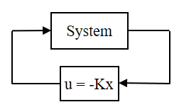
  is the output of the Controller, which represents the control signal of the system—either voltage or torque. The block diagram of the system controlled by the LQR Controller is illustrated in Fig. 3.
| (17) |
Weighting matrix Q:
| (18) |
Energy coefficient R (R > 0)
Solving the Riccati equation, the solution is matrix S:
| (19) |
Control matrix K:
| (20) |
Calculate the matrix K in MATLAB:
| (21) |
The selection of parameters for each controller significantly impacts the control quality of the system. In practice, there are various methods for finding optimal parameters for controllers with typical examples being PSO (Particle Swarm Optimization) as mentioned in the reference [16] and GA presented in reference [17]. In this paper, the authors utilize GA to find the optimal parameters for all three controllers. For the LQR Controller, the control matrix  needs to be optimized. KLQR is influenced by the weighting matrix Q and the energy coefficient R, so GA is used here to determine the best coefficients Q and R. For the Feedback Linearization Controller, the coefficients that directly affect the system response are contained in the matrix
  . For the Fuzzy Controller, it is essential to accurately determine the preprocessing and postprocessing coefficients to ensure that the system output approaches zero as quickly and stably as possible. In this study, GA applied to Fuzzy is only used to optimize the preprocessing coefficients (
 ,
,  ,
,  ,
,  ) and postprocessing coefficients (
 ), without intervening in or altering the fuzzy logic rules.
Parameter |
|
|
|
|
Value | 0.05 | 0.05 | 0.05 | 0.05 |
Symbol | Value | Unit | Description |
| 0.16 |
| Mass of link 1 |
| 0.2 |
| Length of link 1 |
| 0.1 |
| Distance from active joint to center of mass of link 1 |
| 0.00222 |
| Moment of inertia of link 1 |
| 0.066 |
| Mass of link 2 |
| 0.22 |
| Length of link 2 |
| 0.11 |
| Distance from passive joint to center of mass of link 2 |
| 0.00106 |
| Moment of inertia of link 2 |
| 0.0198 |
| Torque constant |
| 0.0198 |
| Back EFM constant (Force constant of motor) |
| 6.835 |
| Resistor of rotor |
| 0.000134 |
| Moment of inertia of rotor |
| 0.000048 |
| Viscous friction constant |
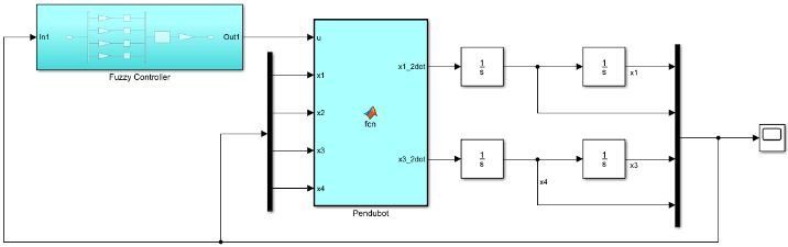
Fig. 4, Fig. 5, and Fig. 6 represent the simulation of the control algorithms using Matlab/Simulink software. In the Pendubot block, the equations are those outlined in section A of II. Similarly, the blocks for Feedback Linear Controller, Fuzzy Controller, and LQR Controller contain the equations presented in section B of II. The output response of the system for each algorithm is observed through the Scope block. All results are presented in section III.
Parameters of the matrix corresponding to the values in the simulation program:

Pre-processing and post-processing parameters:

Control matrix for LQR control:

The simulation results of the linear feedback controller are shown in Fig. 7 and Fig. 8. Link 1 stands upright and stops moving after 0.6s. Link 2 stands upright and stops moving after 0.6s. Thus, the linear feedback controller stabilizes the Pendubot system after 0.6s. The system as shown in the figure has oscillations ranging from 0.003 (rad) to -0.002 (rad) with a steady-state error of 0.8 degrees. The settling time is 0.6s. The results indicate that the two links can stabilize well but the slow settling time is a limitation in balancing the system. From this simulation, it can be observed that when experimenting with other external influencing factors, the feedback linearization algorithm commonly used for SISO systems may not be optimal when applied to a SIMO system like the Pendubot.
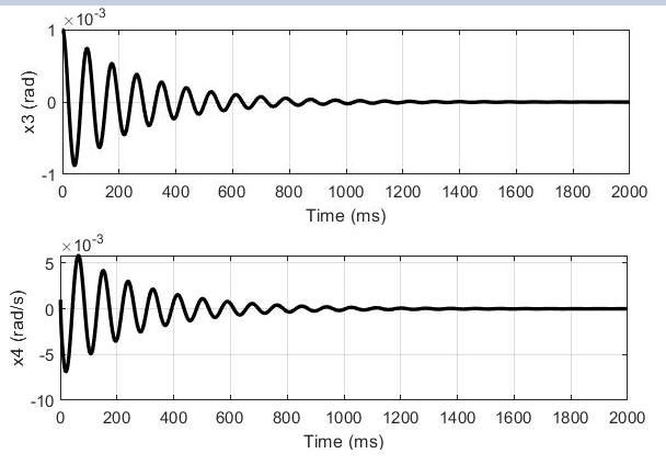
The simulation results of the Fuzzy controller are shown in Fig. 9 and Fig. 10. Link 1 stands upright and stops moving after 1.8s. Link 2 stands upright and stops moving after 1.4s. Thus, the Fuzzy controller balances Pendubot after 1.8s. The system as shown in the figure has a long settling time. During the process of two links reaching the balanced position, the system exhibits strong oscillations, with the amplitude ranging from 0.007 (rad) to -0.007 (rad), and a steady-state error of 1.3 degrees. The results indicate that while two links can stabilize, large steady-state error makes the system susceptible to imbalance when external forces are applied. Large oscillation amplitude during the balancing process significantly slows down settling time, and such continuous oscillations would make experimental implementation challenging. Based on these simulation results, the intelligent control algorithm is not yet optimal for balancing the control of Pendubot.
The simulation results of the LQR controller are shown in Fig. 11 and Fig. 12. Link 1 stands upright and stops moving after 0.4s. Link 2 stands upright and stops moving after 0.15s. Thus, the LQR controller balances the Pendubot system after 0.4s. For the LQR controller, the simulation results show that the system maintains better stability compared to the two control algorithms mentioned earlier. The two links exhibit minimal oscillation during control, leading to a fast settling time of 0.4s and a low steady-state error of 0.2 degrees. Although there is a significant overshoot at the beginning of the control process, the system stabilizes quickly, so it does not significantly affect control quality. The results demonstrate that LQR is a suitable control algorithm for experimental applications with the Pendubot. Given its high control quality, LQR can be combined with other control algorithms to create Swing-Up controllers such as SMC-LQR, EBM-LQR, and FLC-LQR.
Algorithm | Balancing Time (s) |
FLC | 0.6 |
Fuzzy | 1.8 |
LQR | 0.4 |
Through simulation and comparison, it was observed that all controllers balanced Pendubot. Among them, the LQR controller stabilized the system fastest and with the least oscillation. For the Fuzzy controller, the parameters found provided the best response for the best output, but there were still too many oscillations, and the response time was slower compared to the other two controllers (1.8s). For these reasons, it is clear that using the LQR algorithm offers the best control quality and is the most feasible option when tested on an experimental model.
This contribution belongs to the project, which is funded by Ho Chi Minh City University of Technology and Education (HCMUTE), for students of HCMUTE in the year 2025. We also want to give thanks to the PhD. Van-Dong-Hai Nguyen (HCMUTE) helped us in theory.
Minh-Duy Tran, Analysis of Linear and Intelligent Control for Balancing Pendubot System