Journal of Fuzzy Systems and Control, Vol. 3, No 1, 2025 |
Experimental Swing-Up Control of Advanced Sliding and Energy-based Modes for Pendubot
Minh-Duy Tran 1, Minh-Phu Trinh 2, Nguyen-Son Do 3, Thai-Chan Phan 4, Tan-Bao Chau Ngo 5, Viet-Thuan Nguyen 6,
Viet-Dung Ngo 7, Ngoc-Quan Hoang 8, Tan-Phong Trinh 9, Thi-Hong-Lam Le 10,*
1, 2, 3, 4,5, 6, 7, 8, 9, 10 Ho Chi Minh City University of Technology and Education (HCMUTE), Ho Chi Minh City, Vietnam
Email: 1 21151087@student.hcmute.edu.vn, 2 18151103@student.hcmute.edu.vn, 3 18151113@student.hcmute.edu.vn,
4 20151075@student.hcmute.edu.vn, 5 21145081@student.hcmute.edu.vn, 6 21142188@student.hcmute.edu.vn,
7 21142507@student.hcmute.edu.vn, 8 21142582@student.hcmute.edu.vn, 9 21142572@student.hcmute.edu.vn,
*Corresponding Author
Abstract—This study focuses on the implementation and comparative evaluation of two swing-up control strategies—Energy-Based Methods (EBM) and Advanced Sliding Mode Control (ASMC)—for pendubot, a nonlinear two-link robotic system. While previous research has extensively explored balancing algorithms for this model, swing-up strategies have primarily been analyzed through simulations, with limited application to real-world systems. This research addresses this gap by deploying both EBM and ASMC on a physical pendubot model. Practical results are presented to provide the most accurate evaluation of the control quality of each algorithm.
Keywords—LQR; Energy-based Method; Sliding Mode Control; Pendubot; Swing-up
The pendubot is a typical nonlinear mechanical system consisting of two links connected to each other [1]. The first link is fixed to a rotating shaft controlled by a motor, while the second link can freely rotate around the other end of the first link. Many previous studies have focused on balancing the pendubot in an upright position using techniques such as the Linear Quadratic Regulator (LQR) for two-link systems [2], PID control [3], Model Predictive Control (MPC) [4], Fuzzy [5] and Sliding Mode Control (SMC) [6]. It is evident that while there are many studies on balancing algorithms, there has been less focus on swing-up algorithms. An important step in operating this system is the "swing-up" problem — the algorithm that enables the pendubot to automatically move from a resting or free-falling state to the upright position.
In the field of swing-up, various methods have been proposed. Research on swing-up for systems such as the acrobot [7] and the inverted pendulum [8] shows that this problem has been widely studied across different systems. Studies on swing-up for pendubots have also been carried out by many researchers, focusing on algorithms such as Energy-Based Methods (EBM) [9], Sliding Mode Control (SMC) [10], and Fuzzy Control [11]. The research team observed that the most popular method is EBM, while the fastest method is ASMC [12]. However, previous studies have primarily focused on theoretical analysis or simulations, while the practical effectiveness of these two methods on an actual pendubot has not been fully evaluated. This highlights the need for research on the practical application of swing-up algorithms to real-world models.
In this study, we implemented and evaluated two swing-up methods, EBM and ASMC, on a real pendubot model. EBM was selected for its simplicity, ease of implementation, and adaptability to nonlinear dynamic systems. At the same time, ASMC was chosen for its advantages in handling disturbances and uncertainties, making it suitable for real systems with many non-ideal factors. The novelty of this study lies in its direct application to a real pendubot model, providing a comprehensive and practical perspective on these two methods. This research represents a fresh contribution, expanding the understanding of the practical application of modern control methods.
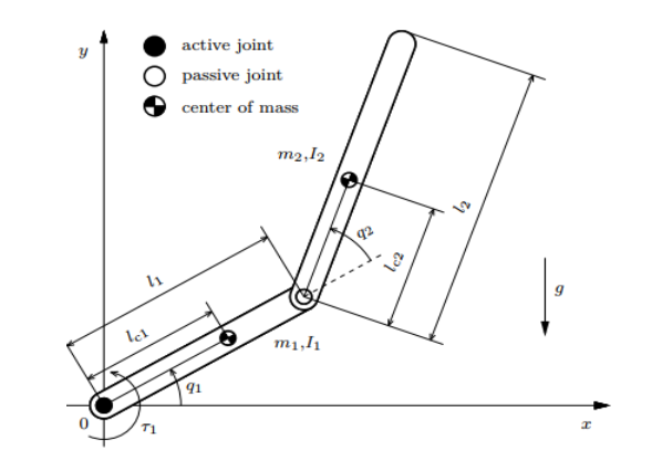
Fig. 1 depicts a pendubot, a two-link robotic system commonly used in nonlinear dynamics and control studies. It consists of two links connected by joints: an active joint at the base, which is controlled by torque, and a passive joint, which moves freely without direct control. System parameters include lengths and masses of links, position of their centers of mass, and angular positions of links relative to horizontal axis. Gravity acts vertically downward. Pendubot is a classic under-actuated system, making it ideal for exploring advanced control strategies such as swing up and balance. System parameters are presented specifically in Table 1.
Symbol | Description | Value | Unit |
| Mass of link 1 | 0.16 |
|
| Length of link 1 | 0.2 |
|
| Distance from active joint to center of mass of link 1 | 0.1 |
|
| Moment of inertia of link 1 | 0.00222 |
|
| Mass of link 2 | 0.066 |
|
| Length of link 2 | 0.22 |
|
| Distance from passive joint to center of mass of link 2 | 0.11 |
|
| Moment of inertia of link 2 | 0.00106 |
|
| Torque constant | 0.0198 |
|
| Back EFM constant (Force constant of motor) | 0.0198 |
|
| Resistor of rotor | 6.835 |
|
| Moment of inertia of rotor | 0.000134 |
|
| Viscous friction constant | 0.000048 |
|
Define the variables as follows to facilitate calculations in the subsequent equations:
| (1) |
In d, the dynamic equations of the Pendubot based on the Euler-Lagrange formulation are as follows [9]:
| (2) |
where:
| (3) |
| (4) |
| (5) |
| (6) |
| (7) |
To match the experiment, we need an equation relating torque to voltage as follows:
| (8) |
where  ;
;  ;
; 
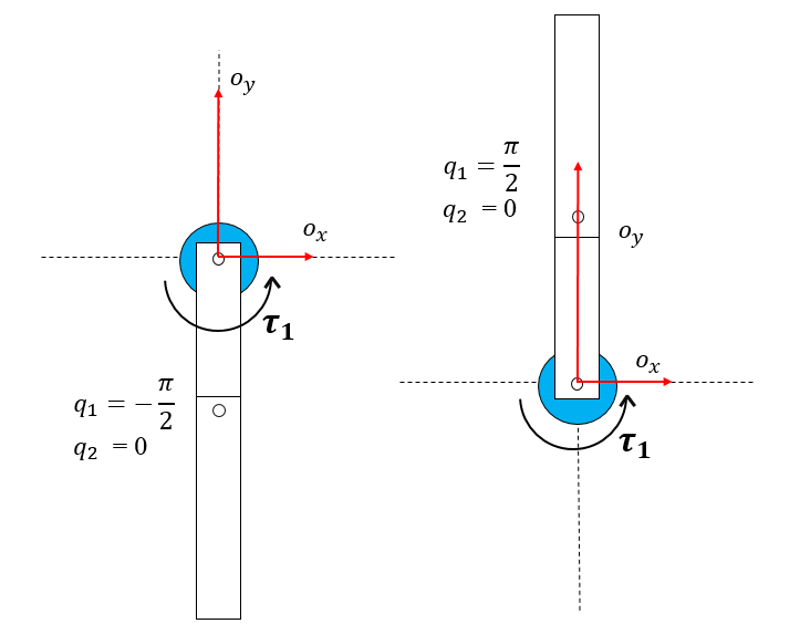
Swing-up for pendubot refers to the process of bringing the system from a downward unstable position  to an upright
  and balanced state. The positions of pendubot are shown in Fig. 2. This is a challenging task because pendubot, being an under-actuated system, cannot direct way to apply force pendulum in upright position. The goal of the Swing-up process is to generate sufficient energy to flip pendulum upwards using the actuators, typically by exploiting dynamics of the system and carefully controlling the torque applied to the joints. Once pendubot reaches an upright position, it can then be stabilized using other control strategies, like LQR or SMC.
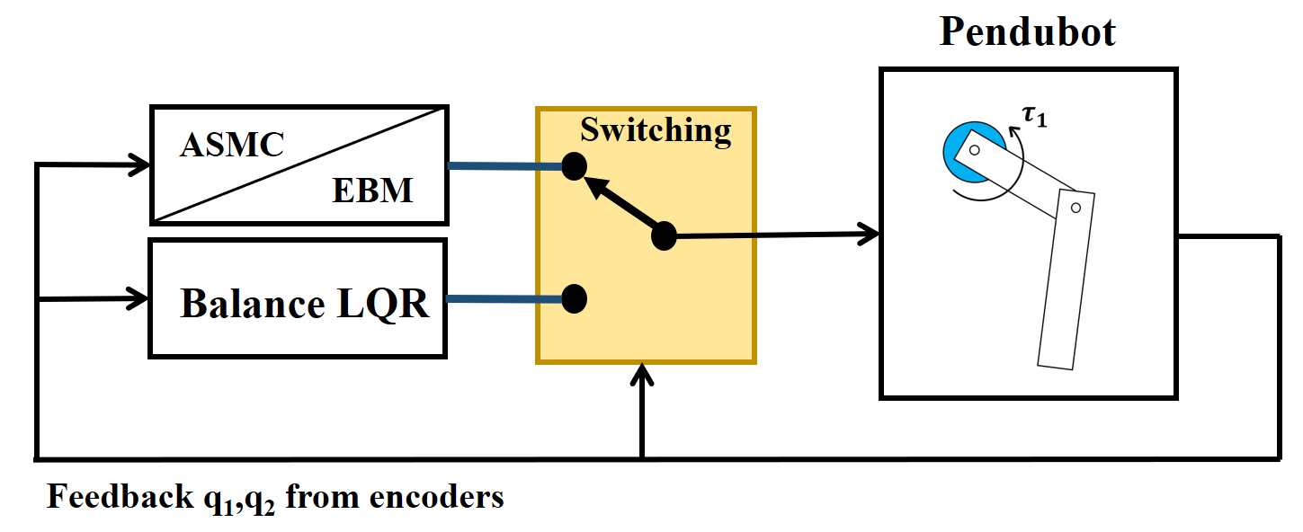
A swing-up controller works by first employing either an EBM or ASMC to build rotational kinetic energy in link 1. As system nears equilibrium position, it transitions to a balance controller once the predefined Switch Condition is satisfied. The integrated algorithm proposed in this paper combines EBM-LQR and ASMC-LQR.
Swing up process for the pendubot is shown in Fig. 3. The angle measurements of link 1 and link 2 are used as feedback to evaluate the Switch Condition. To define an appropriate Switch Condition, it is necessary to analyze the state variables near the equilibrium position and determine a condition that fits the system dynamics effectively.
EBM is an effective control strategy, especially for controlling under-actuated systems like pendubot. This method focuses on controlling the transformation of energy between different energy forms in the system, such as kinetic and potential energy, to achieve the desired control objectives. One of the key advantages of this method is its ability to optimize energy usage, minimizing unnecessary energy consumption. Additionally, this approach is often simpler than other control techniques, as it does not require a detailed model of the system but relies on basic energy factors. This makes EBM an ideal choice for controlling systems with complex dynamics and limited direct control inputs, such as pendubot.
In [14], energy calculations are presented as follows:
Total energy of pendubot is:
| (9) |
Energy of pendubot at upright position is
| (10) |
When  the system reaches a stable state and moves to equilibrium from (9) and (10), we obtain:
| (11) |
In [15], swing up controller is:
| (12) |
Where
| (13) |
According to [15], switching condition is chosen as:
| (14) |
The control parameters following values:  = 246.3,
  = 187,
  = 652.1 and
  = 3. The selection of the parameter ξ also plays a crucial role in determining the system's control quality. If
  is set too high, the timing of the switch may hinder the LQR controller from stabilizing the system. This is because the angular displacement q1 remains far from the desired value, and the angular velocity does not yet meet the conditions required for stable control. Conversely, a lower level of value can improve the system’s behavior after the swing-up phase. However, setting too low creates challenges in achieving the necessary conditions during the swing-up process. After many experiments on the model, this study determined the optimal value for = 1.8.
SMC offers several benefits compared to other control methods. One key advantage is that it does not rely on an exact model, making it well-suited to handling dynamic systems with modeling uncertainties and disturbances. As a nonlinear controller, it outperforms linear controllers in terms of efficiency. The advanced sliding mode controller builds upon the standard version by introducing a slight improvement: it enables  to track a predefined trajectory signal r for the swing-up motion. This design ensures greater stability compared to allowing to rotate at an undefined angle.
The state-space equations of the pendubot system are defined as follows:
| (15) |
The state variables are set as follows:
| (16) |
The error e is now defined as follows [12]:
| (17) |
Construct the sliding surface based on (16) and (17):
| (18) |
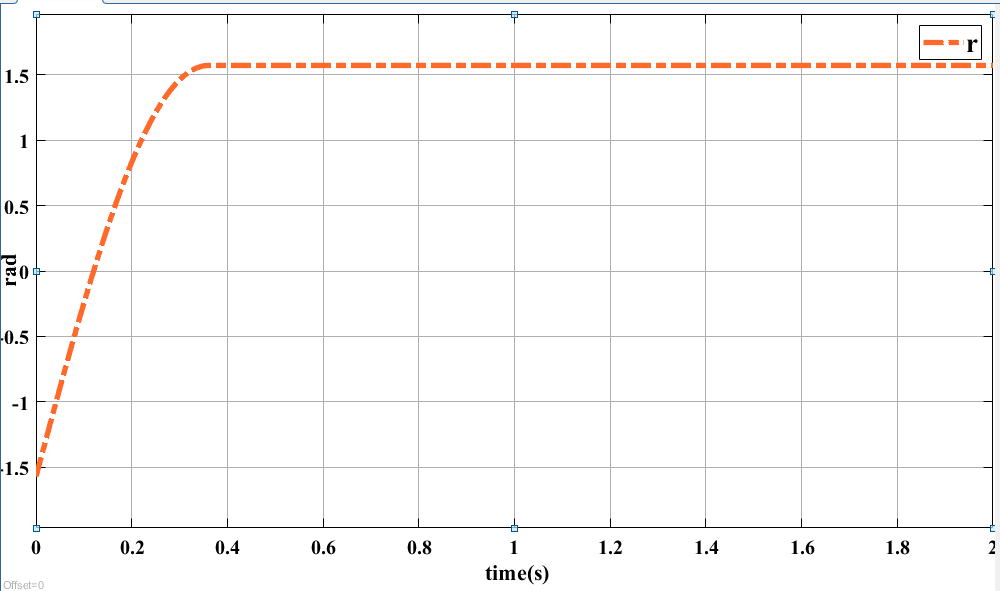
At the TOP position, the reference signal r, which needs to track, is given by (19) and represented in Fig. 4:
| (19) |
From (15) to (19) and follow as [12] we obtain:
| (20) |
Control parameters are as follows: c = 4 and K = 9547. For ASMC, the switching condition is chosen based on the angles of link 1 and link 2 with the conditions  &
& . After many experiments on the model, the value 0.5 was chosen to be the most suitable for triggering the switch.
LQR control algorithm is a widely used optimization method for stabilizing nonlinear systems around an equilibrium point. For pendubot, LQR calculates the optimal control signal by minimizing a cost function that balances state error and control effort. LQR is often combined with other algorithms, such as Sliding Mode Control or energy-based strategies, to perform the swing-up process before stabilizing the system at the desired position. This combination leverages the strengths of both methods to ensure high performance and stability. Calculate the matrix K in MATLAB:
| (21) |
Matrix  and
and  as follows:
| (22) |
| (23) |
The selection of R and Q parameters in the LQR controller is a critical step in achieving optimal control performance. The authors employ the Genetic Algorithm (GA) to optimize these matrices. From (21) to (23), the gain matrix K is determined as follows:

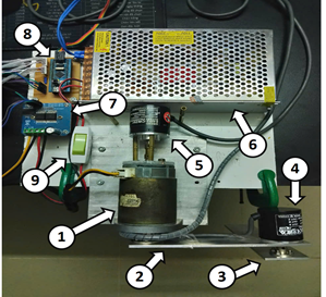
Description of numbers in Fig. 5 is:
Encoder to measure |
|
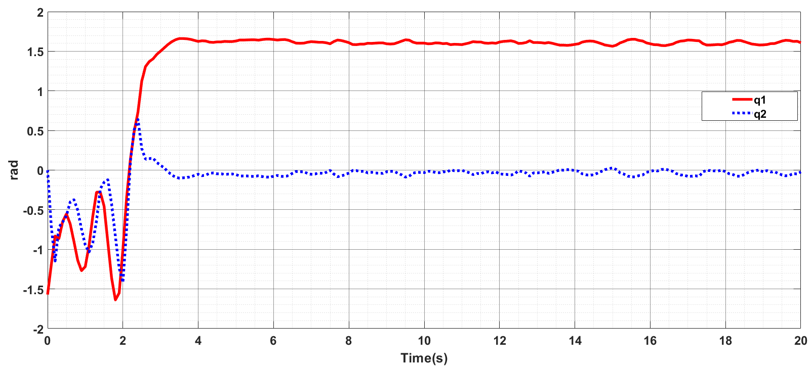
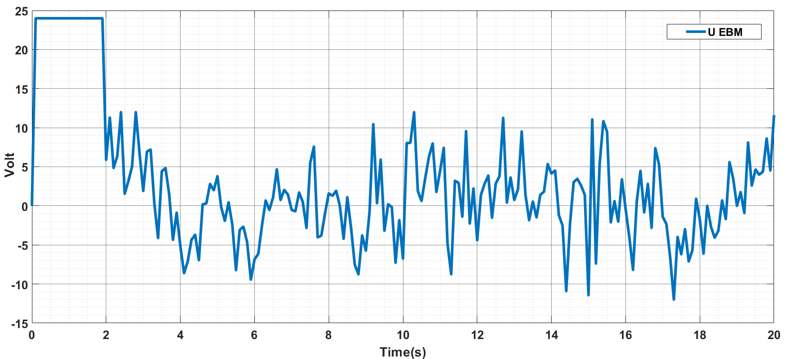
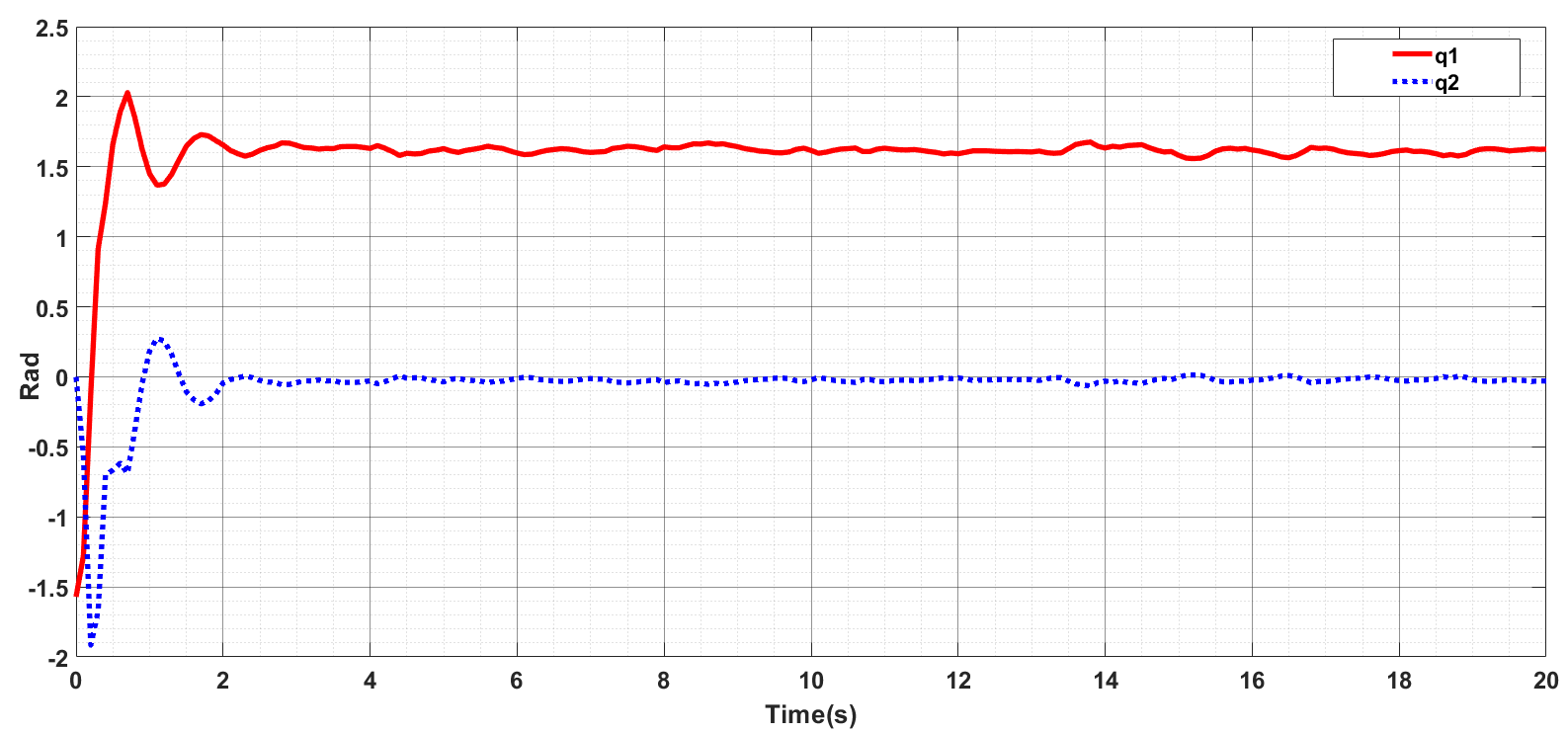
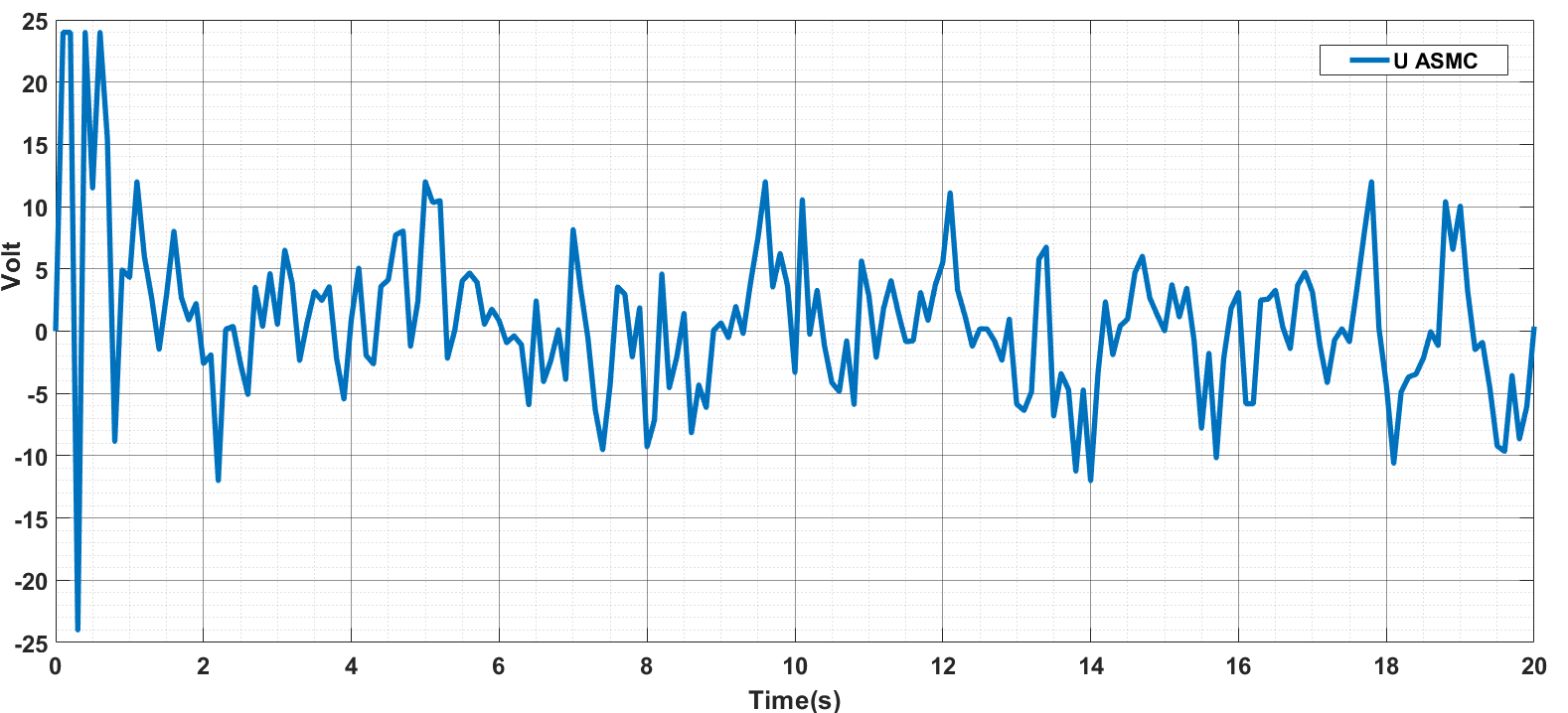
In this experiment, the authors use the parameters q1, q2, and the voltage u supplied to the motor to evaluate the control performance of the algorithms applied for swing-up. The overshoot is analyzed exclusively for since only link 1 directly receives the primary torque from the motor. The experiments for both methods are conducted over a duration of 20 s to ensure consistency in terms of time. The experimental results are presented using graphs with two axes. The x-axis(Time) represents the time during the experiment. In Fig. 6 and Fig. 8, the y-axis indicates the values of the angles q1 and q2 during the swing-up process, measured in radians. Meanwhile, in Fig. 7 and Fig. 9, the y-axis represents the voltage supplied to the motor, measured in Volts (V), and is constrained within the range of -24 V to 24 V.
A. EBM
Fig. 6 shows the output response of pendubot using EBM-LQR algorithm for swing-up control. The system oscillates continuously from 0 to 4 s and begins to stabilize after 4 s. It is noticeable that initially, the amplitude of q1 gradually increases with each oscillation. This aligns with energy-based swing-up principle, where system continuously adjusts the control torque to increase both kinetic and potential energy. The gradual increase in q1 oscillation amplitude over time minimizes instability during the swing-up process, with an overshoot of only 3%. Meanwhile,  oscillates alternately with a smaller amplitude compared to q1, maintaining dynamic relationship between the links. Once swing-up goal is achieved, the system transitions to stabilization using the LQR controller. Oscillations of and decrease and remain close to desired values, with a steady-state error of
  (rad). System stabilizes after approximately 4(s).
An analysis based on Fig. 7, during the time interval from 0 to 4 s, there is a significant fluctuation in voltage, with alternating positive and negative values. This indicates that EBM continuously adjusts the voltage to provide energy to the system, enabling the "swing up" of the robot arm in pendubot. After 4 s, the system switches to LQR control, and the voltage no longer oscillates with large amplitudes as it did in the initial phase. Instead, oscillations become smaller, with values ranging between -10V and 10V. This demonstrates that the LQR method is attempting to maintain the pendulum in a balanced state. These small oscillations compensate for disturbances or minor errors in the system. Voltage oscillations in this phase are neither high in amplitude nor highly variable in frequency because LQR focuses on stabilizing the system and minimizing deviations with high precision rather than generating large dynamics like EBM.
B. ASMC
Fig. 8 shows the output response of the pendubot under the ASMC-LQR algorithm for swing-up control. The system exhibits strong oscillations from 0 to 2 s and begins to stabilize after 2 s. Initially, due to control requirements, q1 receives a large torque to track reference signal r, moving toward an upright balanced position with an overshoot of 25.4%. After achieving the swing-up goal, the system transitions to stabilization using the LQR controller. Oscillations of and decrease and remain close to desired values, with a steady-state error of  (rad). The system stabilizes after approximately 2 s.
Analysis based on Fig. 9, during the first 2 s, the voltage fluctuates strongly. This shows that ASMC is operating with high sensitivity, making significant voltage adjustments to quickly bring the pendubot's pendulum to the target position. The high voltage amplitude and rapid oscillations are characteristic of ASMC, which is designed to effectively correct deviations and handle uncertainties in the system. ASMC prioritizes rapid and accurate responses over smoothness, which explains the strong voltage changes during this phase. After 2 s, the voltage gradually stabilizes within the range of -10 V to 10 V. This reflects that LQR is controlling the motor to maintain the pendulum in a stable balanced state, with smaller and smoother adjustments to minimize errors. The voltage oscillations decrease in amplitude and occur at lower frequencies because LQR focuses on optimizing energy consumption and maintaining system stability.
Algorithm | Overshoot | Settling time (s) |
ASMC | 25,4% | 2 |
EBM | 3% | 4 |
Based on Table 2, the amplitude of SMC oscillations is higher, and the duration of SMC usage is shorter 2 s compared to 4 s in EBM-LQR). SMC responds more quickly and can bring the system to the target state in a shorter time. However, its high overshoot may destabilize the system if not well-controlled. Both methods eventually switch to LQR, but the graph shows that in SMC-LQR, the voltage stabilizes earlier due to SMC rapidly bringing the pendulum closer to the target position.
EBM-LQR and ASMC-LQR both achieve swing-up and stabilization objectives for pendubot. But, each method has its own advantages. EBM-LQR ensures a stable swing-up process with low overshoot but requires 4 s to fully stabilize. In contrast, ASMC-LQR responds faster, stabilizing within 2 s, but exhibits higher overshoot, requiring careful control to avoid instability. ASMC-LQR excels in speed, while EBM-LQR prioritizes stability during the transition process. Through comparison between EBM-LQR and ASMC-LQR, for swinging-up pendubot, each method has its unique strengths and weaknesses, depending on specific evaluation criteria. From these results, we can entirely aim to develop the algorithm further when applying it to the 3-link pendubot or other higher-order nonlinear systems with similar characteristics.
This contribution belongs to the project funded by Ho Chi Minh City University of Technology and Education (HCMUTE), for students of HCMUTE for year 2025. We also want to give thanks to PhD. Van-Dong-Hai Nguyen and Ms. Eng. Thi-Thanh-Hoang Le (HCMUTE) who helped us in theory. Video links of experimental operation are shown in:
https://www.youtube.com/shorts/x4YUfdK4ycs
https://www.youtube.com/shorts/L-slZ2nzrpU
Minh-Duy Tran, Experimental Swing-Up Control of Advanced Sliding and Energy-based Modes for Pendubot