
Journal of Fuzzy Systems and Control, Vol. 3, No 1, 2025 |
Comparative Analysis of Fuzzy Membership Functions for Step and Smooth Input Tracking in a 3-Axis Robotic Manipulator
Phichitphon Chitikunnan 1, Rawiphon Chotikunnan 2,*, Yutthana Pititheeraphab 3, Tasawan Puttasakul 4,
Anantasak Wongkamhang 5, Nuntachai Thongpance 6
1, 2, 3, 4,5 College of Biomedical Engineering, Rangsit University, Pathum Thani, Thailand
Email: 1 phichitphon.c@rsu.ac.th, 2 rawiphon.c@rsu.ac.th, 3 yutthana.p@rsu.ac.th, 4 tasawan.p@rsu.ac.th,
5 anantasak.w@rsu.ac.th, 6 nuntachai.t@rsu.ac.th
*Corresponding Author
Abstract—Robotic manipulators are essential in industrial and medical applications, requiring precise control to improve efficiency and reduce errors. This research looks at how well fuzzy logic controllers using Gaussian, generalized bell, triangular, and trapezoidal membership functions can handle step and smooth inputs for a robot system that is meant to move materials. Critical metrics like steady-state values, overshoot, rise time, integral absolute error (IAE), and root mean square error (RMSE) were tested using five different methods. The results showed that both the Gaussian and extended bell functions found a good balance between being stable and being responsive. This made them useful for situations with moderate to high input levels. While triangular functions displayed enhanced responsiveness, they also revealed heightened overshoot. In contrast, trapezoidal functions demonstrated significant stability at high saturation levels, although they had challenges in attaining smooth transitions. These findings highlight the necessity of choosing membership functions according to particular application needs. This study investigates the utilization of hybrid methodologies and adaptive optimization strategies to improve fuzzy control systems. These concepts offer compelling approaches to improve accuracy and resilience in dynamic robotic settings.
Keywords—Fuzzy Logic Control; Robotic Manipulator; Membership Functions; Step Input Tracking
Robotic and automated systems, encompassing micro-robotics and drones, have profoundly impacted numerous sectors by improving precision, efficiency, and reliability. It is clear that micro-robotics system control [1], intelligent algorithms for microgrid optimization [2], and the creation of linear and nonlinear controllers for tiny drones [3] have all gotten better. Numerous fields have utilized a 2-DOF helicopter system as a specialized control testbed [4]. Other fields include manufacturing processes like welding [5] and assistive technologies like smart wheelchairs [6]-[11] and two-wheeled robotic platforms [12].
Even with these improvements, it is still challenging to get precise control over robotic systems because of errors in repetitive motion, changing system dynamics, and unpredictable environmental conditions [13]-[15]. Such mistakes may present as discernible patterns that impact stability and precision [16]-[18]. Researchers have implemented sophisticated control mechanisms to improve system resilience and consistency. It has been shown that interconnection and damping assignment passivity-based control (IDA-PBC) techniques can help control self-balancing robots better [16], and adaptive nonlinear control algorithms have been made to deal with changes in the system [17]. These strategies jointly ensure sustained performance despite varying settings.
Researchers have investigated various control approaches to address these difficulties [19]-[21]. Proportional-Integral-Derivative (PID) controllers are crucial in motor control because they are simple to use, have been used a lot, and have been shown to work [22]-[24]. There are a number of ways to tune them that can make them work better. To do these things, we need to compare integral state feedback with PID controllers [25], find the best fractional order PID [26], and make regulators for specific tasks, like small conveyor drives [27]. Also, scientists have looked into complex control methods like fuzzy logic [28][29], and fractional order control [30] to make things more accurate and stable. It is possible to get better accuracy, stability, and adaptability in many situations by working together to tune PID and make control methods better [31]-[39].
Fuzzy logic controllers provide enhanced adaptability and robustness compared to conventional PID controllers in many situations [40]-[42]. Self-balancing wheelchair systems are a big use case [43]-[45], and they need accurate angle estimation through sensor fusion methods to stay stable [46]. In addition, advanced control and optimization methods have been used in a wide range of intelligent and process control applications, such as industrial processes [47]-[49] and health-related management (for example, controlling blood glucose levels). Studies [29], and [50] have shown that using both fuzzy logic and neural network-based techniques together makes these methods work better. The stability and adaptability of adaptive and hybrid fuzzy systems, as well as the fuzzy-based methods used in many different applications, have gotten a lot better [51]-[64].
Fuzzy expert systems [65]-[73] and iterative learning control (ILC) [74]-[77] techniques are examples of intelligent controllers that have made control much more accurate and cut down on mistakes. Applications encompass self-balancing robots, omnidirectional robotic platforms, and intelligent wheelchair systems. By using fuzzy logic and optimizing control architectures, researchers are always making systems more accurate, stable, and able to adapt to changing and complex situations. Also, more control methods, like advanced PID design, have made it easier for robotic manipulators to move and move without breaking [78].
This research examines the application of fuzzy logic controllers in robotic manipulator systems to enhance their precision and adaptability. The research examines the efficacy of four membership functions: Gaussian (Gaussmf), Generalized Bell (Gbellmf), Triangular (Trimf), and Trapezoidal (Trapmf). It accomplishes this by the utilization of critical metrics such as steady-state error, rise time, overshoot, and root mean square error (RMSE). As a result, the results show how each membership function acts in different working conditions. This helps us figure out how to control robotic manipulators. The objective of these findings is to enhance the reliability and accuracy of control systems, especially in applications necessitating dynamic reaction and precision.
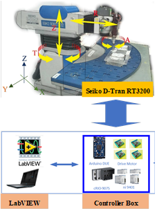
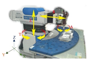
Robotic manipulators are extensively employed in industrial applications for functions including welding, assembling, and painting. The principal categories of industrial robots employed for these functions comprise SCARA robots, Cartesian robots, cylindrical robots, spherical robots, and delta robots. Fig. 1 illustrates a sample robotic manipulator.
This study concentrates on the Seiko D-Tran RT3200 robotic manipulator, classified as a cylindrical robot, and illustrates its applicability as a case study.
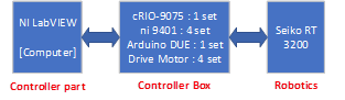
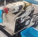
This study utilized the Seiko D-Tran RT3200 robotic manipulator, a cylindrical robotic arm including four joints. These joints facilitate movement along the X-axis (Joint R), vertical displacement along the Z-axis (Joint Z), and rotation inside the X-Y plane (Joints T and A). The control unit was built on the cRIO-9075 platform and written in LabVIEW to manage the four motors. Fig. 2 and Fig. 3 depict the arrangement and assembly of the control unit.
The Seiko D-Tran RT3200 robotic manipulator, seen in Fig. 3, functions according to a discrete-time system equation with a sampling interval of 0.055 seconds. Previous studies, as referenced in [59], and [60], have thoroughly investigated the control algorithms for this robotic manipulator, elucidating its dynamic properties. The studies present the system equation as (1), and Table 1 lists the corresponding coefficients. The table delineates the principal characteristics that characterize the dynamic behavior of the robotic arm.
| (1) |
Joint |
|
|
| |
Joint R | 0. 0333 | -1. 6871 | 0. 6884 | |
Joint T | 0. 0162 | -1. 7077 | 0. 7111 | |
Joint Z | 0. 0140 | -1. 7519 | 0. 7526 |
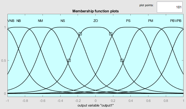
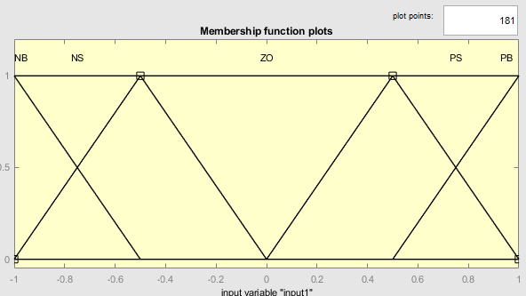
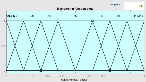
The fuzzy logic control (FLC) system uses approximate reasoning to manage operations and generate solutions. Researchers have thoroughly examined and implemented it across various systems and controllers. The Mamdani method is a prevalent methodology for estimating fuzzy control inputs in the motor control of robotic arms, as seen in Fig. 4. The specification includes two input signals and a single output variable: Input Signal 1 indicates the error signal within the system, whereas Input Signal 2 signifies the fluctuation of the error signal. Both inputs span from -1 to 1 and are governed by five rules each, whereas the output is delineated by nine rules within the same range. The membership functions for these signals are shown in Fig. 5 (Gaussian), Fig. 7 (Generalized Bell), Fig. 9 (Triangular), and Fig. 11 (Trapezoidal). The results of the FLC surface viewer can be seen in Fig. 6, Fig. 8, Fig. 10, and Fig. 12. These three-dimensional images show how the input and output variables are related.
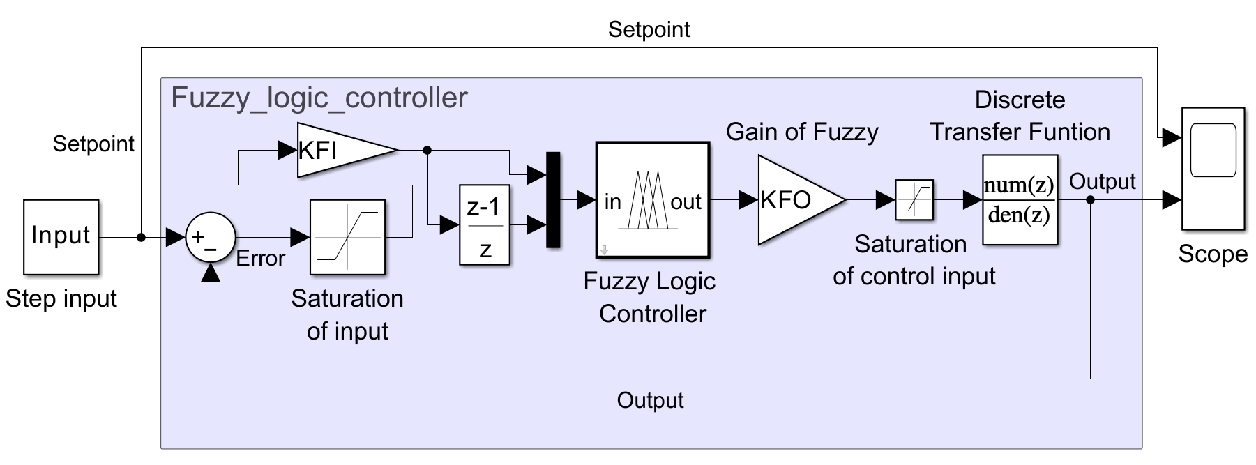
Fig. 13 illustrates the Simulink software that integrates fuzzy logic control for the system. Table 2 shows all of the fuzzy logic controller's membership functions and gives a quick summary of the set range and conditions for each signal.
Input I, f(e) | ||||||
Input II, f(de) | NB | NS | ZO | PS | PB | |
NB | NM | NS | NM | PS | PM | |
NS | NB | NM | NS | PM | PB | |
ZO | VNB | NB | ZO | PB | VPB | |
PS | NB | NM | PS | PM | PB | |
PB | NM | NS | PM | PS | PM | |
The input values for joints R, T, and Z are constrained by saturation limits of -40 to 40 for Joint R, -15 to 15 for Joint T, and -20 to 20 for Joint Z, as illustrated in Fig. 5, Fig. 7, Fig. 9, and Fig. 11. The error range is parameterized by KFI, while the fuzzy logic input scaling factors are defined as 1/40 for Joint R, 1/15 for Joint T, and 1/20 for Joint Z. The control input saturation limit for all three joints is set between -100 and 100, with a scaling factor of 100 for KFO.
This section explores Mamdani fuzzy logic models featuring two inputs and one output. Each input is governed by five rules, while the output is defined by nine rules, as depicted in Fig. 5, Fig. 7, Fig. 9, and Fig. 11, respectively. Table 2 outlines the rule base used in these models. The fuzzy system estimation is based on the centroid defuzzification method, represented by (2). Centroid defuzzification calculates the center of gravity of the fuzzy set along the x-axis, where  denotes the membership value for each point
  in the universe of discourse.
| (2) |
The Fuzzy PD controller system incorporates the differential term  , calculated as the difference between
  and
and  , as shown in (4). The system response can be approximated using (2), which can be adapted into (5) for representation and explained further in Fig. 14. Input 1, represents the error , passes through the gain value GE for estimation. The membership functions for Input 1 and Input 2 illustrate the error.
  and its derivative
  , respectively. Substituting GCE with the gain value derived from the closed-loop control system output, the control signal
  at time step
  becomes a nonlinear function of both error and error derivative changes, as expressed in (5). The amplification rate
  adjusts the signal .
The error and its derivative are defined as
| (3) |
| (4) |
| (5) |
These equations form the basis for designing the Fuzzy PD controller, enabling precise system control through nonlinear adjustments of error and error derivative changes.
The efficacy of the fuzzy logic control system was assessed by five experimental trials performed on the joints R, T, and Z of the robotic manipulator. Each test included diverse step inputs and continuous functions to assess the system's responsiveness and precision. Results were evaluated using Gaussian, Generalized Bell, Triangular, and Trapezoidal membership functions, as specified in Table 3 to Table 17 and depicted in Fig. 15 to Fig. 19.
In the first test, step inputs with low setpoints (10 for Joint R, 3.75 for Joint T, and 5 for Joint Z) were applied. The system exhibited stable performance across all membership functions. Minimal overshoot and rapid rise times were observed, demonstrating efficient response under low input values. The performance metrics, including steady-state values, %OS, rise times, IAE, and RMSE, are presented in Table 3 to Table 5 and visualized in Fig. 15.
The second test had moderate step inputs of 30, 11.25, and 15 for joints R, T, and Z, respectively. The system exhibited effective control, with Gaussian and Gbellmf demonstrating reduced overshoot relative to Trimf and Trapmf. The system's adaptation to increased input values resulted in marginally elevated rise times and RMSE values, as illustrated in Table 6 to Table 8 and Fig. 16.
In the third test, high-step input setpoints of 50, 18.75, and 25 were used for joints R, T, and Z. The system continued to perform reliably but showed increased IAE and RMSE values. Trimf achieved the fastest rise time but exhibited a higher overshoot, while Trapmf provided the most stable response. Detailed metrics are displayed in Table 9 to Table 11 and Fig. 17.
In the fourth test, the system was assessed using maximum step input setpoints of 70, 26.25, and 35 for joints R, T, and Z, respectively. The system exhibited strong performance, with Trapmf attaining minimal overshoot and RMSE. Gaussian and Gbellmf provide a compromise between velocity and stability, as outlined in Table 12 to Table 14 and Fig. 18.
The conclusive assessment concentrated on the system's capacity to monitor seamless functional inputs. Continuous transitions were implemented for joints R, T, and Z, normalized for the experiment. Trapmf displayed the greatest IAE and RMSE values, whereas Trimf consistently exhibited the lowest error metrics, rendering it the most efficient in smooth-tracking situations. Table 15 to Table 17 encapsulates the results, while Fig. 19 illustrates them.
The experimental results demonstrate the adaptability and accuracy of the fuzzy logic control system under diverse input situations. Gaussian and Gbellmf demonstrated consistent performance across several circumstances, although Trimf excelled in scenarios requiring rapid response. Trapmf exhibited exceptional stability with elevated input saturation, highlighting its dependability for rigorous applications.
Type | SteadyState | %OS | RiseTime | IAE | RMSE |
Gaussmf | 9.888 | 11.270 | 0.330 | 2.801 | 2.335 |
Gbellmf | 9.859 | 6.760 | 0.330 | 2.980 | 2.438 |
Trimf | 9.948 | 16.090 | 0.220 | 2.379 | 2.174 |
Trapmf | 9.852 | 4.500 | 0.440 | 3.398 | 2.662 |
Type | SteadyState | %OS | RiseTime | IAE | RMSE |
Gaussmf | 3.663 | 18.670 | 0.220 | 1.069 | 0.817 |
Gbellmf | 3.641 | 12.910 | 0.275 | 1.115 | 0.841 |
Trimf | 3.709 | 21.450 | 0.165 | 0.878 | 0.767 |
Trapmf | 3.635 | 9.970 | 0.275 | 1.238 | 0.917 |
Type | SteadyState | %OS | RiseTime | IAE | RMSE |
Gaussmf | 4.961 | 17.170 | 0.275 | 1.576 | 1.224 |
Gbellmf | 4.952 | 11.860 | 0.330 | 1.636 | 1.267 |
Trimf | 4.983 | 21.340 | 0.275 | 1.380 | 1.145 |
Trapmf | 4.952 | 9.200 | 0.440 | 1.824 | 1.372 |
The examination of system responses for setpoints of 10, 3.75, and 5 for joints R, T, and Z, respectively, as illustrated in Fig. 15, showcases the efficacy of Gaussian (Gaussmf), Generalized Bell (Gbellmf), Triangular (Trimf), and Trapezoidal (Trapmf) membership functions. For Joint R, Trapmf demonstrated the minimal overshoot (4.5%) and optimal steady-state stability, while Trimf attained the quickest rising time (0.22 seconds) but exhibited the maximum overshoot (16.09%). The Joint T findings demonstrate that Trimf achieved the quickest rising time (0.165 seconds) and the lowest RMSE (0.767), while Trapmf offered a balanced performance with little overshoot (9.97%). For Joint Z, Trimf exhibited the lowest RMSE (1.145) and the quickest rising time (0.275 seconds), while Trapmf provided the most stable response with minimal overshoot (9.2%). The findings shown in Table 3 to Table 5 demonstrate the trade-offs of speed, stability, and accuracy across various membership functions.
The study of how the system reacts to setpoints of 30, 11.25, and 15 for joints R, T, and Z shows how the Gaussian (Gaussmf), Generalized Bell (Gbellmf), Triangular (Trimf), and Trapezoidal (Trapmf) membership functions work, as shown in Fig. 16 and explained in more detail in Table 6 to Table 8. For Joint R, Trapmf demonstrated the minimal overshoot (2.15%) and consistent performance, whereas Trimf had the quickest rising time (0.275 seconds) but exhibited the maximum overshoot (10.36%). Joint T exhibited effective control, with Gbellmf achieving a low overrun of 8.27% and moderate error metrics, whereas Trimf provided a speedy rising time of 0.220 seconds but resulted in a greater overshoot of 14.88%. For Joint Z, Trimf exhibited the lowest error metrics (IAE and RMSE) and the quickest rising time (0.275 seconds), whereas Trapmf offered more steady control with negligible overshoot (5.29%). The results demonstrate a trade-off among speed, stability, and accuracy contingent upon the selected membership function for various joints and setpoints.
Looking at how the system reacts to setpoints of 50, 18.75, and 25 for joints R, T, and Z, shown in Fig. 17, tests how well the Gaussian (Gaussmf), Generalized Bell (Gbellmf), Triangular (Trimf), and Trapezoidal (Trapmf) membership functions work. For Joint R, Trapmf demonstrated minimal overshoot (1.47%) and optimal stability, whereas Trimf displayed the quickest rising time (0.385 seconds) with a little greater overshoot (7.58%). In Joint T, Trimf exhibited the fastest response with the briefest rising time (0.275 seconds) and the lowest RMSE (4.775), whereas Trapmf demonstrated a consistent performance with negligible overshoot (4.68%). For Joint Z, Trimf exhibited the lowest RMSE (7.069) and the quickest rising time (0.385 seconds), whereas Trapmf provided the most consistent response with minimal overshoot (4.54%). Performance measures encompassing steady-state values, %OS, rise times, IAE, and RMSE are consolidated in Table 9 to Table 11. The results underscore the trade-offs between response speed, stability, and accuracy of the evaluated membership functions.
Type | SteadyState | %OS | RiseTime | IAE | RMSE |
Gaussmf | 29.660 | 6.870 | 0.385 | 10.247 | 8.096 |
Gbellmf | 29.579 | 3.760 | 0.495 | 10.805 | 8.280 |
Trimf | 29.842 | 10.360 | 0.275 | 8.473 | 7.464 |
Trapmf | 29.554 | 2.150 | 0.605 | 13.288 | 9.279 |
Type | SteadyState | %OS | RiseTime | IAE | RMSE |
Gaussmf | 10.986 | 12.190 | 0.275 | 3.686 | 2.808 |
Gbellmf | 10.921 | 8.270 | 0.330 | 3.820 | 2.848 |
Trimf | 11.124 | 14.880 | 0.220 | 3.015 | 2.623 |
Trapmf | 10.897 | 5.550 | 0.440 | 4.515 | 3.171 |
Type | SteadyState | %OS | RiseTime | IAE | RMSE |
Gaussmf | 14.880 | 11.480 | 0.385 | 5.520 | 4.178 |
Gbellmf | 14.861 | 7.530 | 0.440 | 5.677 | 4.250 |
Trimf | 14.946 | 15.230 | 0.275 | 4.765 | 3.882 |
Trapmf | 14.858 | 5.290 | 0.550 | 6.798 | 4.731 |
Type | SteadyState | %OS | RiseTime | IAE | RMSE |
Gaussmf | 49.431 | 5.070 | 0.440 | 19.655 | 14.789 |
Gbellmf | 49.296 | 2.890 | 0.495 | 20.650 | 15.098 |
Trimf | 49.732 | 7.580 | 0.385 | 16.486 | 13.705 |
Trapmf | 49.248 | 1.470 | 0.605 | 20.388 | 14.567 |
Type | SteadyState | %OS | RiseTime | IAE | RMSE |
Gaussmf | 18.308 | 9.920 | 0.385 | 6.866 | 5.111 |
Gbellmf | 18.197 | 7.230 | 0.385 | 7.132 | 5.183 |
Trimf | 18.535 | 12.280 | 0.275 | 5.734 | 4.775 |
Trapmf | 18.149 | 4.680 | 0.440 | 6.932 | 4.995 |
Type | SteadyState | %OS | RiseTime | IAE | RMSE |
Gaussmf | 24.801 | 9.120 | 0.440 | 10.427 | 7.601 |
Gbellmf | 24.773 | 6.440 | 0.495 | 10.765 | 7.739 |
Trimf | 24.910 | 12.390 | 0.385 | 9.038 | 7.069 |
Trapmf | 24.759 | 4.540 | 0.550 | 10.080 | 7.373 |
The study of system responses at setpoints of 70, 26.25, and 35 for joints R, T, and Z, shown in Fig. 18, shows that the Gaussian (Gaussmf), Generalized Bell (Gbellmf), Triangular (Trimf), and Trapezoidal (Trapmf) membership functions work well when the inputs are high. For Joint R, Trapmf demonstrated the minimal overshoot (1.19%) and consistent performance, while Trimf attained the quickest rising time (0.385 seconds) with a greater overshoot (6.02%). For Joint T, Trimf exhibited superior responsiveness with the quickest rising time (0.33 seconds) and the lowest RMSE (7.233), whereas Trapmf demonstrated a balanced performance with little overshoot (4.57%). For Joint Z, Trimf attained the minimal RMSE (10.747) and the quickest rising time (0.385 seconds), whereas Trapmf produced consistent outcomes with the least overshoot (4.48%). Table 12 to Table 14 consolidates the comprehensive performance measures, which include steady-state values, %OS, rise times, IAE, and RMSE. These findings underscore the versatility of various membership functions in managing elevated setpoints efficiently.
Type | SteadyState | %OS | RiseTime | IAE | RMSE |
Gaussmf | 69.203 | 3.870 | 0.550 | 32.465 | 22.793 |
Gbellmf | 69.012 | 2.190 | 0.605 | 34.575 | 23.407 |
Trimf | 69.620 | 6.020 | 0.385 | 26.666 | 20.875 |
Trapmf | 68.936 | 1.190 | 0.605 | 31.114 | 21.707 |
Type | SteadyState | %OS | RiseTime | IAE | RMSE |
Gaussmf | 25.624 | 7.810 | 0.385 | 10.964 | 7.826 |
Gbellmf | 25.468 | 5.750 | 0.440 | 11.553 | 7.992 |
Trimf | 25.943 | 9.990 | 0.330 | 9.029 | 7.233 |
Trapmf | 25.385 | 4.570 | 0.440 | 10.510 | 7.454 |
Type | SteadyState | %OS | RiseTime | IAE | RMSE |
Gaussmf | 34.732 | 7.300 | 0.550 | 16.982 | 11.666 |
Gbellmf | 34.687 | 5.130 | 0.605 | 17.791 | 11.954 |
Trimf | 34.879 | 10.220 | 0.385 | 14.396 | 10.747 |
Trapmf | 34.661 | 4.480 | 0.550 | 15.476 | 11.046 |
This study looks at how the system reacts to smooth function inputs across joints R, T, and Z, as shown in Fig. 19. It does this by testing how well the Gaussian (Gaussmf), Generalized Bell (Gbellmf), Triangular (Trimf), and Trapezoidal (Trapmf) membership functions work. For Joint R, Trimf demonstrated superior accuracy with the lowest IAE (33.693) and RMSE (5.879), while Trapmf revealed the highest error metrics, indicating less effective tracking. For Joint T, Trimf consistently showed superior performance, achieving the lowest IAE (8.108) and RMSE (1.186), whereas Trapmf had higher error levels. Similarly, for Joint Z, Trimf exhibited superior performance with the lowest IAE (14.757) and RMSE (2.414), while Trapmf displayed the highest error metrics, highlighting its inadequacies in handling smooth inputs. Table 15 to Table 17 presents detailed performance metrics for each joint, emphasizing Trimf's adaptability and precision in addressing continuous input variations.
Type | IAE | RMSE |
Gaussmf | 54.197 | 8.537 |
Gbellmf | 62.369 | 9.477 |
Trimf | 33.693 | 5.879 |
Trapmf | 70.141 | 10.310 |
Type | IAE | RMSE |
Gaussmf | 13.931 | 1.815 |
Gbellmf | 16.741 | 2.109 |
Trimf | 8.108 | 1.186 |
Trapmf | 20.752 | 2.644 |
Type | IAE | RMSE |
Gaussmf | 23.734 | 3.577 |
Gbellmf | 26.447 | 3.943 |
Trimf | 14.757 | 2.414 |
Trapmf | 32.696 | 4.748 |
All five simulation results demonstrate that the fuzzy logic control system in a robotic manipulator, which employs several membership functions (Gaussian, Generalized Bell, Triangular, and Trapezoidal), presents both advantages and disadvantages. Gaussian and generalized bell functions always showed balanced performance, combining stability and accuracy across a range of input conditions. This makes them suitable for tasks that need some flexibility, like medical or industrial robot precision. Triangular functions demonstrated swift responsiveness and negligible inaccuracy, which are advantageous for real-time applications, but their propensity to overshoot may induce instability in sensitive jobs. Conversely, trapezoidal functions demonstrated superior stability under high saturation inputs, rendering them suited for demanding or high-disturbance situations; however, their elevated error rates in smooth input tracking diminish their appropriateness for precision manipulations.
Subsequent research ought to concentrate on hybrid methodologies to address the specific limitations of these membership functions. Combining Gaussian's balance and Triangular's flexibility could lead to a control system that is both quick and stable. Adaptive tuning methods that use machine learning or optimization algorithms may also help the fuzzy control system work better in changing or unexpected situations. These improvements will let these systems handle more complicated tasks, like multifunctional robotic arms and real-time adaptive automation, making sure they are accurate and dependable.
The parameters of this study's simulation designs, which included five scenarios, may not accurately represent all operational settings. The lack of diverse load circumstances, alternative robotic designs, or external disturbances limits the applicability of the results. To make the proposed methods more reliable, more research should include a wider range of test scenarios, such as those using other robotic systems, changes that happen in the real world, and more system parameters. These initiatives would yield more thorough insights into the efficacy and constraints of fuzzy logic controllers across many settings.
The research examined the application of fuzzy logic controllers employing Gaussian, extended bell, triangular, and trapezoidal membership functions for step and smooth input tracking in a robotic manipulator system. The results indicated that each membership function possesses distinct advantages and disadvantages, underscoring the need to select the appropriate function for the task at hand. Both Gaussian and Gbellmf performed effectively, demonstrating an adequate equilibrium of velocity and stability. This rendered them appropriate for situations necessitating exact control and adaptability. Trimf was more responsive and had faster rise times, which made it good for real-time applications. Trapmf, on the other hand, was very stable when input saturation was high, but it had trouble tracking input smoothly. To make things more stable and flexible in changing situations, researchers should look into hybrid methods that combine the best parts of different membership functions. Combining Gaussian and triangular functions may address the trade-offs between velocity and stability. Moreover, incorporating adaptive tuning mechanisms powered by artificial intelligence or machine learning could enable real-time optimization, hence enhancing the effectiveness of fuzzy logic controllers in unpredictable conditions. These advancements could significantly improve the utilization of fuzzy systems in several industrial and robotic domains. The current study limited its simulation scope by excluding variable load circumstances, external disturbances, and varied robotic configurations. Subsequent studies should seek to broaden the experimental framework to encompass a greater variety of real-world scenarios and dynamic settings. This method will find out how resilient and adaptable the suggested techniques are and help make fuzzy logic controllers that are more useful and adaptable. These developments will facilitate the development of effective solutions for intricate and dynamic robotic tasks in actual contexts.
The researcher would like to thank the Research Institute, Academic Services Center, and College of Biomedical Engineering, Rangsit University for the grant of research funding to the research team. Furthermore, it is confirmed that the project has been reviewed by the Ethics Review Board of Rangsit University, with reference number RSUERB2024-002, which certifies that the research does not involve human subjects.
Phichitphon Chitikunnan, Comparative Analysis of Fuzzy Membership Functions for Step and Smooth Input Tracking in a 3-Axis Robotic Manipulator