Journal of Fuzzy Systems and Control, Vol. 3, No 1, 2025 |
Position Control of an Experimental Three-Degree-of-Freedom Actuated Articulated Robot Arm utilizing PID Controller
Dinh-Hieu Vo 1,*, Nam-Chau Le 2, Thi-Y-Nhi Nguyen 3, Tran-Phuong Huynh 4, Nhat-Truong Huynh 5, Kim-Huy Tran 6, Ba-Chinh Nguyen 7, Truong-Giang Do 8, Gia-Huy Tran 9, Van-Dong-Hai Nguyen 10,
1, 3, 4, 5, 6, 7, 8, 9, 10 Faculty of Electrical and Electronics Engineering, Ho Chi Minh City University of Technology and Education (HCMUTE), Ho Chi Minh City (HCMC), Vietnam
2 Faculty of Economics, Ho Chi Minh City University of Technology and Education (HCMUTE), Ho Chi Minh City (HCMC), Vietnam
Email: 1 22151084@student.hcmute.edu.vn, 2 22151054@student.hcmute.edu.vn, 3 21125252@student.hcmute.edu.vn,
4 21142153@student.hcmute.edu.vn, 5 21142199@student.hcmute.edu.vn, 6 21142110@student.hcmute.edu.vn,
7 21142498@student.hcmute.edu.vn, 8 20151355@student.hcmute.edu.vn, 9 21151109@student.hcmute.edu.vn,
*Corresponding Author
Abstract—In this paper, we present an experimental three-degree-of-freedom (3-DOF) articulated robot arm. A hardware setup using Arduino – a popular and cheap processor- is utilized to make an experimental model suitable for a small laboratory. PID control is applied to position control for our robot for set-point positions. The experimental results prove that PID controller is suitable for this real model. Besides, calibration of PID parameters also proves that the experimental PID suits the PID theory. Thence, this research is a reference for individuals who are implementing a real model for a small laboratory.
Keywords—PID Control; 3-DOF Robot Arm; Manipulator; Arduino
Robot arms are popular models in both academic and industry. Their popularity makes them a criterion for standardizing them [1]. However, the flexibility in designing and controlling them still stimulates research. In [2][3], 2-DOF robot arms are presented. PID control [2] and LQR control [3] are used successfully for these robot arms. With 2-DOF, robot arms cannot work in 3D space. Because of the requirement of developing a mechanical structure, other links are added to create a 3-DOF robot arm. A design is shown in [4]. Applications of the implementation for PLC are suggested in [5] and [6]. However, using PLC, there is no algorithm in control and PLC is so expensive for students to practice. The stability of PLC is based on hardware technology. In our opinion, with only simple hardware, the development of the algorithm can be used to increase the quality control of the system. In [7], kinetic inverse and forward calculation of 3-DOF robot arm are done, and a simulation of using PID control for 3-DOF robot arm is proved, but no experiment is described. The need to apply algorithms in hardware still exists.
The development of Arduino opens a direction for cheap and easy-to-make robot models for the laboratory [8]. Thence, building a 3-DOF robot arm based on Arduino is a suitable direction for widening cheap models for kinds of people for training and research.
Besides many flexible methods for robots, such as sliding control [9] or intelligent control [10], PID controller, which is a single loop controller introduced in 1940 [11], is still the most popular due to its simple structure. Its application is shown in [12] for chemical process control calibration and in [13] for temperature control. In the laboratory, this control method is popularly used to a DC motor [14]. Using DC motors to apply for other kinds of systems, such as a submarine model [15]. However, this is only a simple single input-multi output (SISO) system. Thence, the challenge in control is limited. A more complicated multi-input-multi-output (MIMO) system, such as a 3-DOF robot arm, gives a better solution for increasing the challenge in training control theory for students in the laboratory.
In this research, we develop an experiment for a 3-DOF articulated robot arm based on our real model in HCMUTE. Hardware platform is described and proved through PID control for set-point position. Calibration is tested to confirm its suitability to theory. Thence, our research is a reference for the idea of building a simple and effective model for a control robot arm for laboratories.
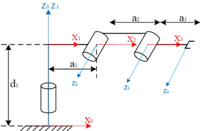
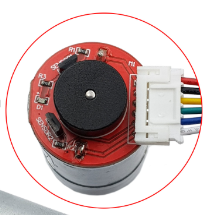
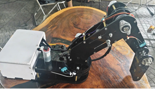
Mathematical structure of 3-DOF robot arm is shown in Fig. 1.This robot imitates a human arm, designed to perform basic actions through the integration of DC motor (Fig. 2) and Matlab/Simulink for control in section III.B. The First motor is used for right and left motion. Second and third motors are used for the elevation of the arm [2]. Forward kinematics analysis is used to compute the location and orientation of each joint in the robotic arm.
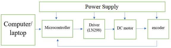
In this platform, 12V DC sources are used to supply all DC motors and the Arduino. In an experimental model, these three DC motors get six wires. Red and black colors are the two wires of the motor power. Green color is GND of encoder. Blue color is VCC of encoder (3.5 20V). Yellow and white colors are the output of A and B of the encoder. Motor is controlled by PWM signals [2].
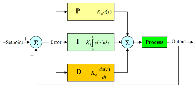
Structure of PID control is shown in Fig. 3. PID controller in governor designs appeared in the 1890s [16]. It was later developed in automatic ship steering systems. PID is a classical method of automation and control theory. It is popular due to its easy calibration of trial control mode [1].
Three main components of PID control are  ,
,  ,
,  . determines reaction to current error, determines reaction to the sum of recently appeared errors, D determines reaction according to the rate of error changing. Sum of these three parts contributes to the control mechanism, such as speed control of a motor, in which value depends upon current error, also depend on the accumulation of previous error, and D predicts future error based on the current rate of change [6]. Theory of calibration of PID parameters is shown in Table 1.
, , and parameters tuningGain | Rising time | Over-shoot | Settling time | Error Steady-State |
Increasing | Decrease | Increase | Tiny increase | Decrease |
Increasing | Tiny decrease | Increase | Increase | Large decrease |
Increasing | Tiny decrease | Decrease | Decrease | No change |
PID formula blocks are described by formula (1) to formula (4)
| (1) |
| (2) |
| (3) |
| (4) |
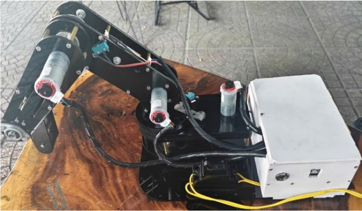
The robot’s movements are intended to mimic those of a human arm. The section describes 3D modeling, hardware using SolidWorks 2022 (Fig. 4). Fig. 5 and Fig. 6 illustrate the overall structure of the three-dimensional real experimental model. All of the robotic arm's links are individually designed using software, allowing for precise customization and modularity. This approach enables the arm to attach various screwdriver bits to the end effector, making it versatile for tasks like removing multiple screws in different configurations. Once the individual components are designed, they are assembled into a cohesive system, enhancing the understanding of the arm's mechanics and functionality. This modular design not only improves operational efficiency but also simplifies maintenance and upgrades.
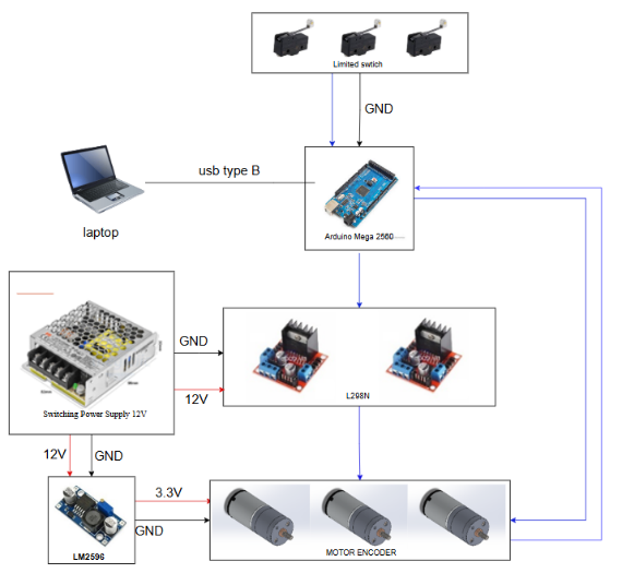
In this project, the robot was designed using SolidWorks 2022 software. Thence, an experimental model is shown in Fig. 5 and Fig. 6. This model is then used to perform simulations according to the block diagram in Fig. 7. And, the total structure of connection is shown in Fig. 8.
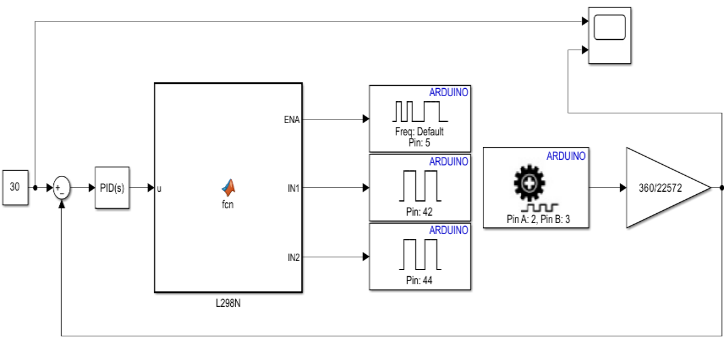
Fig. 9 represents the simulation of the control algorithms using MATLAB/Simulink software 2023B.
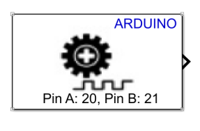
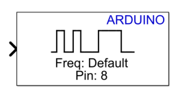
Encoder block (Fig. 10) outputs tick count from a quadrature encoder on a rotating motor connected to an Arduino board. Every increment in tick count of the encoder indicates that the motor is rotating clockwise. Every decrement in tick count of encoder indicates that the motor is rotating counterclockwise. Total tick count represents the incremental position of the rotating motor [17]. PWM block (Fig. 11) generates square pulses of varying duty cycle depending on input value sent to block on the Arduino hardware pin. This block enables a digital output to provide a range of different power levels, similar to that of an analog output [17].
Based on the experimental model, the embedded program is based on Simulink using MATLAB 2023b software. The program, as shown in Fig. 15, includes blocks for reading output values, the main program, and the PID. The PID control parameters are shown in Table 2, with sampling time of 0.001s.
DC motor |
|
|
|
1 | 108 | 0.01 | 4.5 |
2 | 108 | 0.01 | 4.5 |
3 | 108 | 0.01 | 4.5 |
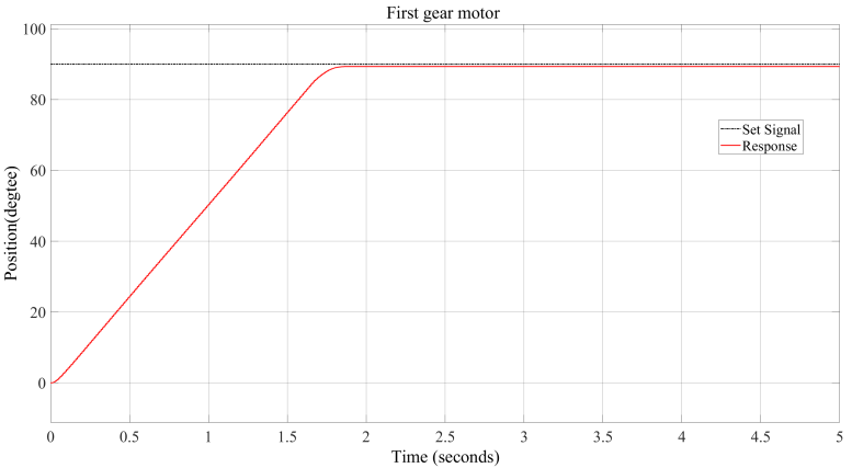
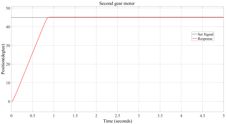
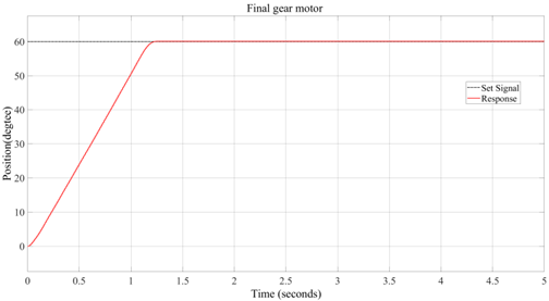
Fig. 12 show the response graphs of rotational joints 1, 2, and 3, respectively. The set angles are represented by the black dashed line, while the response angles are shown by the red line.
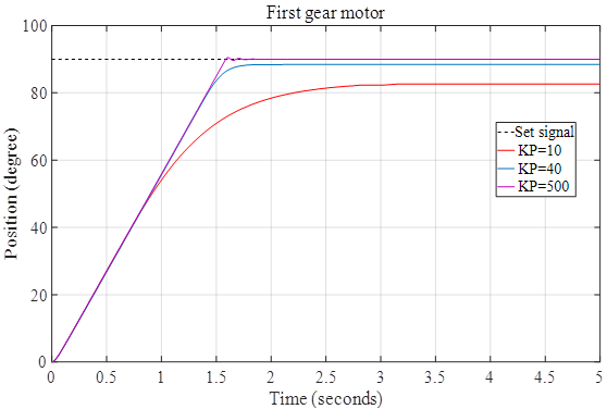
From control parameters in Table 3, response of the system is shown in Fig. 13. It is observed that if  is low, the output response does not reach the set angle value. Conversely, if is too high, it causes overshoot. The set angles are represented by the black dashed line, while the red, blue, and purple lines show the response graphs of the first rotational joint when is 10, 40, and 500, respectively. It can be seen that when = 10 and 40, the steady-state errors are approximately 7 and 2, respectively. On the other hand, when = 500, there is a small overshoot, and steady-state error is zero.
(a) |
(b) |
(c) |
=10, =40, and =500.Case |
|
|
|
1 | 10 | 0.01 | 4.5 |
2 | 40 | 0.01 | 4.5 |
3 | 500 | 0.01 | 4.5 |
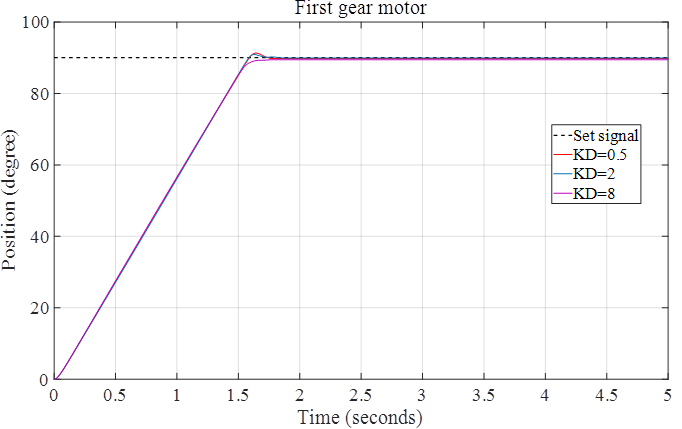
From control parameters in Table 4, response of the system is shown in Fig. 14. It is observed that as  increases, both overshoot and settling time decrease. The set angles are represented by black dashed line, while the red, blue, and purple lines show the response graphs of the first rotational joint when is increased from 0.5 to 2 and 8. It can be observed that when = 0.5 and 2, the overshoot is greater than zero and gradually decreases as increases.
Case |
|
|
|
1 | 108 | 0.01 | 0.5 |
2 | 108 | 0.01 | 2 |
3 | 108 | 0.01 | 8 |
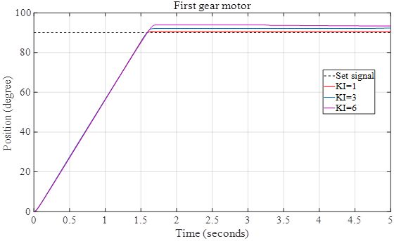
=0.5, =2, and =8From control parameters in Table 5, response of the system is shown in Fig. 15. It is observed that as  increases, the output value exceeds the set value. The set angles are represented by the black dashed line, while the red, green, and purple lines show the response graphs of the first rotational joint when is increased from 1 to 3 and 6. It can be seen that when exceeds the value of 1, the steady-state error becomes negative.
Case |
|
|
|
1 | 108 | 1 | 4.8 |
2 | 108 | 2 | 4.8 |
3 | 108 | 3 | 4.8 |
=0.5, =2, and =6In this paper, we focus on position control for a 3-DOF articulated robot arm at set-point positions. This research implements for the case that inverse and reverse kinetic calculations were provided. We present a hardware platform for this model. In our research, a MATLAB-embedded program for Arduino is shown. Through this experimental system, PID control for MIMO system is utilized and proved to control well each link at set-point positions. Also, PID parameters adjustments are operated to test the PID calibration rule. Thence, through adjustment, is confirmed to decrease settling error and shorten the settling time and increase overshoot; in this case is confirmed to increase overshoot; in this case is confirmed to make the system more vibrate. The calibration suits the theory of PID method. In experimental, increasing gives more overshoot. It suits the theory. However, the mechanical part of DC motor makes the system delayed. Thence, it takes more time for the system to be stabilized at set-point. The characteristics suit the theory, but the simulation time should be longer for a better view. Bigger value of makes overshoot smaller. And, this main characteristic suits the PID theory.
This paper belongs to the project for students of HCMUTE in year 2025 and it is funded by HCMUTE. We, authors, want to give thanks for that support. Video link of operation of system is: https://www.youtube.com/watch?v=IA029uSBq-Q
Dinh-Hieu Vo, Position Control of an Experimental Three-Degree-of-Freedom Actuated Articulated Robot Arm utilizing PID Controller