(1)

(2)

(3)
Journal of Fuzzy Systems and Control, Vol. 1, No 1, 2023 |
Hydraulic Power System Control using State Feedback Controller (SFC)
Fahmizal 1*, Jimmy Trio Putra 2, Sekar Fatimawardhani 3, Hari Maghfiroh 4
1,2, 3 Department of Electrical Engineering and Informatics, Universitas Gadjah Mada, Yogyakarta, Indonesia
4 Department of Electrical Engineering, Universitas Sebelas Maret, Surakarta, Indonesia
Email: 1 fahmizal@ugm.ac.id, 2 jimmytrioputra@ugm.ac.id, 3 sekarfati@gmail.com, 4 hari.maghfiroh@gmail.com
*Corresponding Author
Abstract— In an electrical network, generators work and provide power to the loads. When the load on the generator increases, the speed of the generator decreases then resulting in a reduction in the frequency of the network. This paper was designed within the state feedback controller (SFC) to improve the hydraulic power system performance. The performance of the proposed controller is compared with simple feedback controller (FC) in the simulation environment. The load variation was tested which is 5%, 10%, and 20% variation. The testing results show that in terms of steady state error (SSE) and overshoot, the SFC is superior. In terms of settling time, the FC method is faster. Since it quickly reaches steady event not getting into set-point. The overall, it can be concluded that SFC can give better performance than FC in the frequency control of a hydraulic power system.
Keywords— Power System, Control, State Feedback
A system will give more benefits when there is control over it. The control system has a considerable influence on life, which can improve the performance of a system and reduce the production costs used. Basically improving the performance of a system does not need to change the system plant, so it is only done by adding a sub-system called the controller [1].
The control system is very much found in the industrial world because its existence causes the industrial world to be optimal [2]. At present, the hydraulic system is widely used in the industrial world, because the industrial world requires a power system in the form of a hydraulic system. The selection of hydraulic system is a power system because it can work quickly and efficiently. In conventional hydraulic systems, the system works by utilizing human resources. So as to overcome and solve the problems that occur in conventional hydraulic systems, a control system is designed so that the input frequency can increase and decrease automatically according to the specified needs [3]. Of course, the control system can also make the hydraulic power system work stably without the need for human resources to stabilize it [4], [5].
This paper will show how the state-feedback controller (SFC) is designed for a closed-loop hydraulic power system. So that a more stable system response will be produced and can save more power. The load frequency controller is designed and implemented to automatically balance the power and the desired specifications for each system. The performance will be compared to the simple feedback control system.
In this paper, the system is designed with a constant frequency of 50 Hz, and the load change with 5%, 10%, and 20% variations. The SFC controller can only be applied when all state variable values can be measured, and the system is completely controllable and observable. Part II contains an explanation of the hydraulic power system and its working principles, the system model of the hydraulic power system including the parameters used, and the mathematical model used in the hydraulic power system. Part III explains the simulation results of the hydraulic power system, and the results of the signal response from the closed loop system are presented. Then Section IV will give a conclusion from the simulation results that have been carried out.
A hydraulic system is generally a form of power transfer by using a conducting medium in the form of liquid fluid to obtain greater power than the initial power released. The basic principle of hydraulics is that if a liquid is subjected to pressure, the pressure will spread in all directions without increasing or decreasing [1].
The basic components contained in the hydraulic system consist of pumps, reservoirs, directional valves, check valves, pressure relief valves, selector valves, actuators, and filters [6]-[7]. In the hydraulic power system, there is a reservoir that functions to accommodate hydraulic fluid and pumps as well as to transmit fluid to the hydraulic circuit. The reservoir provides great pressure to provide feed to the pump along with air flowing in the compensator to compensate for the fluid that will come out. In this paper, the control system objective is to maintain frequency stability. The method used to determine the gain in the full-state feedback control system is pole placement.
In general, a good operation applied to a hydraulic power system is parallel operation, because, with the parallel operation, the system will still produce a constant frequency value even though the load is varied [7]. In this paper, state space equations are used to analyze and design the controller. To design the state space equation, the system parameters are needed, so that the running system will work optimally and in accordance with the setpoint [8]. The parameters used in the hydraulic power system are shown in Table 1. To design a hydraulic power system, three system components are used, namely the generator system, turbine system, and power system [1], [2]. Each of them is represented sequentially in the equations G1(s), G2(s), and G3(s). The transfer function equations G1(s), G2(s), and G3(s) are in (1), (2), and (3), respectively.
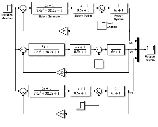
Fig. 1 shows the block diagram of the hydraulic power system, where there are transfer function equations from the generator system, turbine system, and power system. There is a load change step that functions so that the speed of the generator system and turbine system does not reset when the speed decreases. There is a step droop characteristic which is represented by (1/RP), where the value of the droop characteristic is 20.
Table 1. Hydraulic Power System Parameters
Variable | Remark | Value |
Rp | Continuous speed reduction | 0.05s |
RT | Speed reduction | 0.4s |
TG | Temporary | 0.2s |
TR | Generator constant time | 5s |
M | Constant time reset | 6s |
TW | Inertia | 1s |
D | Water start time | 1pu |
| (1) |
| (2) |
| (3) |
Based on the block diagram in Fig. 1, the input frequency is 50 Hz then enters the generator system. The generator system and turbine system are arranged in series and reduced by the load change input, from the transfer function equation obtained, they are operated in series with the power system and fed back with the droop characteristic. The variations used in the load change are 5%, 10%, and 20% of the input frequency in the hydraulic power system.
The optimal electric power system is a system that can maintain frequency stability over the input load. The cause of frequency instability is the increase in load received by the system so that the power in the generator system must be increased to enter the turbine system and then the system maintains a frequency of 50 Hz [9], [10]. In the hydraulic power system, the turbine system converts potential energy into mechanical energy. The mechanical energy is then converted into electrical energy by the generator. The position of the turbine system is almost equivalent to the generator system, namely turning the input of electrical energy into output [9], [11], [12]. The turbine in the fluid provides a thrust function to rotate the propeller, these rotations cause the turbine shaft to move and be forwarded to the generator to be converted into electrical energy.
The principle of the load frequency system is to control the speed of the turbine in an isolated area so that the frequency value of electrical energy will be maintained [13]. In the frequency, the setting system is regulated through a control loop [14]-[16]. The power system is a component that functions t{o distribute power from the prime mover. This component has a feedback control. In general, the power system functions to increase stability by adjusting the performance of the generator [17]-[20].
The total transfer function model of the hydraulic power system is shown in (4). Based on the total transfer function obtained, it can be used to determine the state space equation with the help of MATLAB. The state space model results obtained are shown in (5). In the LQR controller, control can only be applied when all state variable values can be measured, and the system must be completely controllable and observable.
| (4) |
| (5) |
A system can be said to be completely controllable if the order of the controllability matrix is equal to its rank or the determinant is not equal to zero. To find out the controllability matrix in MATLAB, use the syntax "Cm = ctrb (A,B)". Based on the controllability test in MATLAB, the cm matrix is obtained as in (6). The order and rank of the cm matrix are both equal to 4, and the determinant of the cm matrix is 1. This means that the hydraulic power system is completely controllable.
| (6) |
The system is completely observable if the order of the observability matrix is the same as the rank or the determinant is not equal to zero. To find out the observability matrix in MATLAB, use the syntax "Om = obsrv (A,C)". Based on the observability test in MATLAB above, the Om matrix is obtained as follows (7). The order and rank of the Om matrix are both equal to 4, and the determinant of the Cm matrix is 0.0025 or in other words, it is not equal to zero. This means that the hydraulic power system is completely observable. Based on the controllability and observability test on the state space hydraulic power system equation, it can be said that the addition of the LQR controller is feasible to be applied to this system since it was controllable and observable.
| (7) |
In this section, we will show the simulation results of the hydraulic power system on simple feedback control and SFC control. Simple feedback means only using one feedback gain to the measured variable. On the other hand, the SFC control needs feedback and gains as much as the state used.
The system is designed in a closed loop which is given input in the form of a constant frequency of 50Hz. The input frequency in the series operation of the generator system and turbine system and the frequency is automatically reduced because there is a load change that changes with the input frequency. In the next stage, if the speed drops, the value from the previous process will be accumulated again in the turbine system and is sustainable, so the system does not reset. The block diagram on Simulink for the hydraulic power system is shown in Fig. 2.
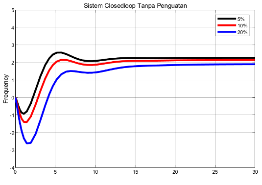
The results is depicted in Fig. 3, three variations were carried out for a load change of 5%, 10%, and 20%, where the color for each variation respectively is black, red, and blue. While the value given to load change is obtained from the multiplication of each variation with the input frequency because the input frequency is constant. Thus, the value of each variation of 5%, 10%, and 20% with respect to the input frequency is 2.5, Hz, 5Hz, and 10Hz, respectively. The feedback gain is chosen as (1/RP), where the value of the droop characteristic is 20.
Based on the graphical results shown in Fig. 3, the signal response with poor performance is obtained, because there is still a steady state error (SSE) which is getting bigger from each variation of 5%, 10%, and 20%. The resulting settling time is also quite large, the average is ±9 seconds. Fine-tuning is needed to get better performances.
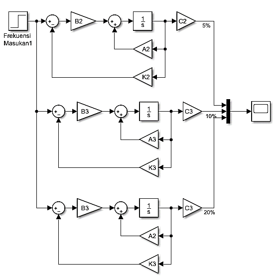
As comparison, a hydraulic power system design using full-state feedback control reinforcement is added. The value of K is searched using Pole-placement method. In the MATLAB, syntax "Ackerman" for each K2, K3, and K4, namely "Kp = acker (A, B, rp)", where rp = roots(P) is used. Each Kp value is entered at the K gain in the block diagram of Fig. 4.
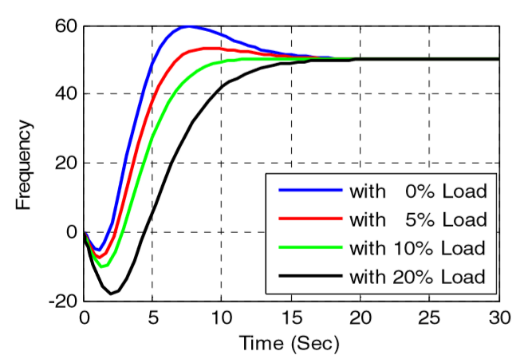
The resulting system response is shown in Fig. 5. Ignoring the blue line signal response or 0% load variation, then the response results are 0%, then the system response results for the hydraulic power system variations of 5%, 10%, and 20% respectively are indicated by red, green, and black. Based on the online response of each signal, the signal is getting better at increasing load variations. Overall, the system can maintain to the desired frequency event there is load variation.
Based on the simulation results, the performance parameters of the two-control method is resumed in Table 2. It can be seen that the hydraulic power system using the SFC controller reduces errors and overshoot. The average SSE of SFC is 0% whereas for simple state feedback is 57.50%. The SFC controller also has lower overshoot with the average of 1.70%. On the other hand, the simple state feedback has average overshoot of 7%. In terms of settling time, the simple state feedback is faster to be stable, but it has high SSE and cannot reach the set-point. Therefore, it can be concluded that the SFC has better performance than simple state feedback one.
Table 2. Results Comparison
Controller | Parameters | 5% | 10% | 20% | Mean |
Feedback control | SSE (%) | 47.00 | 47.50 | 48.00 | 57.50 |
Overshot (%) | 13.00 | 1.00 | 0.00 | 7.00 | |
Settling Time(s) | 9.60 | 5.20 | 13.50 | 9.43 | |
SFC control | SSE (%) | 0 | 0 | 0 | 0 |
Overshot (%) | 5.00 | 0.00 | 0.05 | 1.70 | |
Settling Time(s) | 11.00 | 8.50 | 13.00 | 10.83 |
This paper has studied the hydraulic power system using feedback control and state feedback control (SFC). Full-state feedback control gain’s K is designed using the pole-placement method to improve system performance and reduce the effects of frequency loads. The results prove that the SFC control system has been designed properly so that the performance of the hydraulic power system is getting better. Based on the simulation results that have been carried out, it can be concluded that the SFC control system can eliminate the steady-state error. The next point is that the SFC control system can also reduce settling time so that the system achieves stability more quickly.
Fahmizal, Hydraulic Power System Control using State Feedback Controller (SFC)