Journal of Fuzzy Systems and Control, Vol. 3, No 2, 2025 |
Firefly Algorithm-Based PID Optimization for Active Suspension Systems in Electric Vehicles
Van-Cuong Bui 1,* , Van-Quynh Le 2, Anh-Nguyet Ngo 3, Chi-Huan Canh 4
1,2,4 Faculty of Vehicle and Energy Engineering, Thai Nguyen University of Technology, Vietnam
3 Jiangsu University, China
Email: 1 cuongbui@tnut.edu.vn, 2 lequynh@tnut.edu.vn, 3 ngoanhnguyet04@gmail.com, 4 huanoto@tnut.edu.vn
*Corresponding Author
Abstract—This paper presents the optimization of a PID controller for an active suspension (AS) system in the electric vehicle (EV) using the Firefly Algorithm (FA). The objective is to enhance ride comfort and vehicle stability by minimizing body acceleration (BA), suspension dynamic deflection (SDD), and wheel dynamic load (WDL). The proposed AS system is based on a quarter-car EV model. Random road excitation and harmonic disturbances are selected as input conditions to evaluate system performance. The FA is employed to determine the optimal PID parameters, improving the system’s overall efficiency. The AS system and PID controller are developed in the Matlab/Simulink environment. The results demonstrate that the optimized PID-controlled active suspension (AS-OPID) achieves significant performance improvements, reducing the root mean square (RMS) values of BA, SDD, and WDL by 23.05%, 19.78%, and 13.31%, respectively, compared to a passive suspension (PS) system under random road conditions at a vehicle speed of 70 km/h. These improvements highlight the effectiveness of FA in optimizing control parameters, leading to better ride quality and vehicle stability. The findings confirm that FA-based PID optimization is a promising approach for enhancing AS performance in EVs.
Keywords—Firefly Algorithm; Active Suspension; PID Controller; Ride Comfort; Electric Vehicle
Electric vehicles have garnered significant attention due to their potential to reduce emissions and dependence on fossil fuels. However, the transition from internal combustion engine (ICE) vehicles to EVs introduces new challenges, particularly in terms of ride comfort and vehicle stability [1], [2]. The absence of a traditional ICE and the unique in-wheel motor configuration in EVs significantly impact ride comfort [3]-[5]. Consequently, the suspension system plays a crucial role in mitigating these adverse vibrations. In general, the suspension systems designed for EVs are similar to those in conventional vehicles. However, to meet the growing demand for improved ride comfort, stability, and safety, active suspension (AS) systems have been introduced [6]-[12]. AS systems are typically equipped with hydraulic actuators [6]-[9], allowing vehicles to achieve superior ride quality and adapt to various road conditions. However, accessing the actuators in the AS system is relatively complex. Therefore, instead of focusing solely on hydraulic actuators, researchers have shifted their attention to developing advanced control strategies for AS systems. The objective of the control strategy is to generate an active force that enhances ride comfort and vehicle stability. Several typical control strategies have been proposed, such as the Fuzzy Logic Controller (FLC) [13], [14], H∞ controller [15], [16], Linear Quadratic Regulator (LQR) [17], [18], Sliding Mode Controller (SMC) [19], [20], and Model Predictive Controller (MPC) [21], [22]. Although these control strategies have demonstrated superior vibration isolation performance for active suspension systems, their practical implementation remains challenging. For instance, FLC does not require an accurate mathematical model but often relies on empirical rules and lacks a systematic tuning process. In contrast, H∞ and LQR controllers depend heavily on precise system modeling and can be difficult to design for highly nonlinear dynamics. SMC, while robust, suffers from chattering issues, and MPC demands high computational resources, making real-time application difficult.
The PID controller, composed of proportional, integral, and derivative terms, is simple to implement. As a result, PID controllers have been widely applied in many industrial control systems [23]-[26]. In the field of vehicle control, PID controllers have also been used for active suspension systems [27]-[30]. However, tuning the parameters Kp, Ki, and Kd typically relies on the Ziegler-Nichols technique, which may not yield optimal performance for complex systems. To address this issue, various optimization algorithms have been proposed, including Genetic Algorithm [31], Particle Swarm Optimization [32], Grey Wolf Optimization [33], [34], and Firefly Algorithm [35]. Among these, the Firefly Algorithm has gained attention due to its efficiency in finding optimal PID parameters and its strong convergence capabilities in non-linear search spaces. Therefore, in the present study, a quarter-car active suspension system model is developed to analyze the effects of PID control optimized using FA. The novelty of this research lies in the application of FA to optimize PID control parameters for active suspension systems in EVs, aiming to minimize key suspension performance metrics, including BA, SDD, and WDL. While previous studies have explored various optimization techniques, FA has not yet been effectively utilized in this context.
The remainder of this paper is structured as follows. Section II presents the mathematical modeling of the quarter-car active suspension system. Section III introduces the PID controller and the Firefly Algorithm for parameter optimization. Section IV provides the simulation results and performance evaluation of the optimized controller. Finally, Section V concludes the study and discusses potential future research directions.
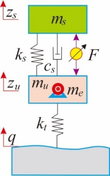
To evaluate the performance of the FA-optimised PID controller for the AS system compared to the PS system, a quarter-car EV model is established, as shown in Fig. 1. In this model, the motor mass is incorporated into the unsprung mass, representing the distributed drive configuration of electric vehicles. This unique drivetrain concept holds great potential for future EVs. However, the increased unsprung mass significantly amplifies vibrations, posing challenges to ride comfort and stability.
In Fig. 1, ms, mu, and me represent the sprung mass, unsprung mass, and motor mass, respectively, zs and zu denote the vertical displacements of the sprung and unsprung masses, respectively, ks and kt correspond to the stiffness of the suspension system and the tire, respectively, while cs is the damping coefficient, q represents the road excitation, and F is the force exerted by the active suspension system.
Based on Fig. 1, the equations of motion of the vehicle can be written as follows:
| (1) |
Where 
The Laplace transform of Equation (1) can be represented as follows:
| (2) |
| (3) |
The solution can be written as follows:
| (4) |
where
The transfer functions are determined as
| (5) |
| (6) |
| (7) |
The state variables chosen are:
| (8) |
Variables representing the system output
| (9) |
The state-space representation of the equations is as follows:
| (10) |
Where

 ,
, 
 ,
, 
The EV model parameters are listed in Table 1.
Parameters | Values |
ms | 300 kg |
mu | 30 kg |
me | 35 kg |
ks | 19000 N/m |
cs | 1000 N.s/m |
kt | 200000 N/m |
Road disturbances are the primary cause of undesirable vibrations in vehicles. In this study, random road excitation and harmonic disturbances are selected as input conditions to evaluate system performance.
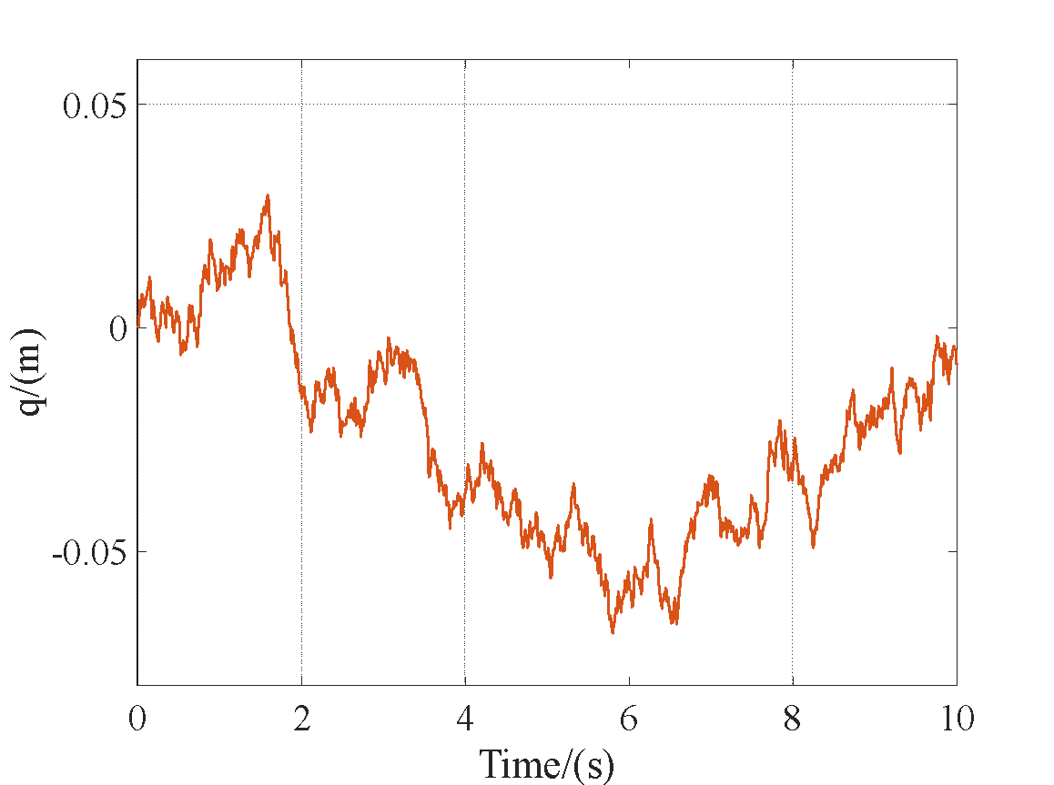
The mathematical model of random road excitation using a filtered white noise pavement model in the time domain can be expressed as follows [36]:
| (11) |
where q is road excitation; w(t) is the Gaussian white noise with a mean of zero; f0 represents the lower cut-off frequency, which is 0.01 Hz; and G0 represents the roughness coefficient of the road surface; v is the speed of the vehicle, v=70 km/h. The value of the B-class road surface is G0=6.4 × 10⁻⁵ m3. From Equation (11), the random road input is simulated in the MATLAB/Simulink environment, as shown in Fig. 2.
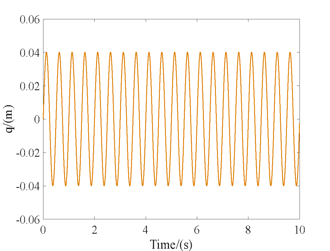
The mathematical equation describing the harmonic road input can be written as follows [37]:
| (12) |
Under these road conditions, the excitation frequency is set to f= 2Hz. From Equation (12), the harmonic road input is simulated in the MATLAB/Simulink environment, as shown in Fig. 3.
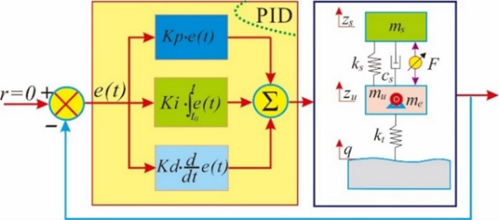
To generate the control force F for the active suspension system, a PID controller is selected. The conventional PID (CPID) controller structure and the control mechanism applied in this study are illustrated in Fig. 4. The equation governing the control force F generated by the PID controller can be expressed as follows:
| (13) |
In this study, The CPID controller can be determined using a manual tuning method.
The parameters Kp, Ki, and Kd significantly impact the performance of the PID controller. Therefore, an optimized PID controller (OPID) with optimal values for Kp, Ki, and Kd is determined using the Firefly Algorithm. FA is a nature-inspired optimization technique known for its strong global search capability and fast convergence, making it highly effective in solving complex optimization problems. Due to these advantages, FA has been widely applied in various fields, including engineering [38], machine learning, and control system optimization [35]-[40]. FA is based on the behavior of fireflies, which communicate using bioluminescence to attract others. The algorithm assumes that the attractiveness of a firefly is proportional to its brightness, and brightness is related to the objective function of the optimization problem. Fireflies with lower objective function values attract others, guiding the search toward optimal solutions.
Assuming that the light intensity of a firefly is I, the mathematical equation is written as [35], [38]:
| (14) |
where γ is the absorption coefficient and (I0) is the initial value at (r = 0).
The parameter β is given by
| (15) |
Mathematically, the movement of a firefly i towards a brighter firefly j is governed by [35], [38]:
| (16) |
To determine the optimal parameters for the PID controller, the objective function is defined as follows:
| (17) |
| (18) |
| (19) |
where BA(y), SDD(y), and WDL(y) represent the RMS values for the AS system, while BA(pas), SDD(pas), and WDL(pas) represent the RMS values for the PS system.  ,
, , and
, and  are coefficients, with the sum of all
  equal to 1. The same parameters are provided to the FA, and the variable limits are given in Table 2.
Parameters | Values |
Firefly size | 20 |
Max generation | 100 |
β | 1 |
γ | 0.2 |
α | 0.25 |
Lower bound of variables | [1000, 100, 0.1] |
Upper bound of variables | [5000, 4500, 1000] |
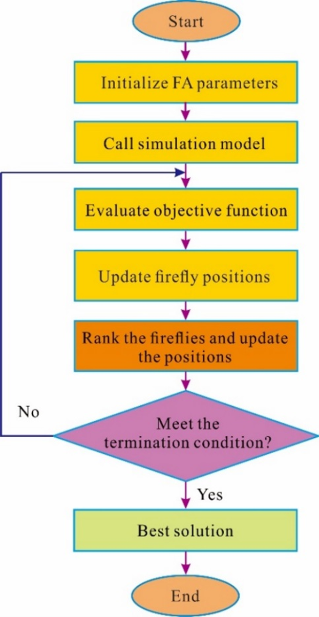
Based on the parameters in Table 1 and Table 2, along with the objective function in Equation (17), the FA optimization program is developed in MATLAB. The sim function is utilized to call the Simulink model of the AS system and the PID controller. The process of searching for the optimal PID controller parameters follows the algorithm flowchart shown in Fig. 5. The FA algorithm iteratively adjusts the control parameters to minimize the objective function. Once the predefined number of iterations and convergence criteria are met, the optimal parameters obtained are Kp = 4830.26, Ki = 3946.76, and Kd = 260.42.
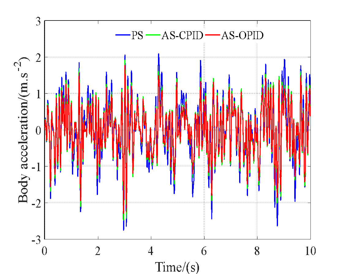
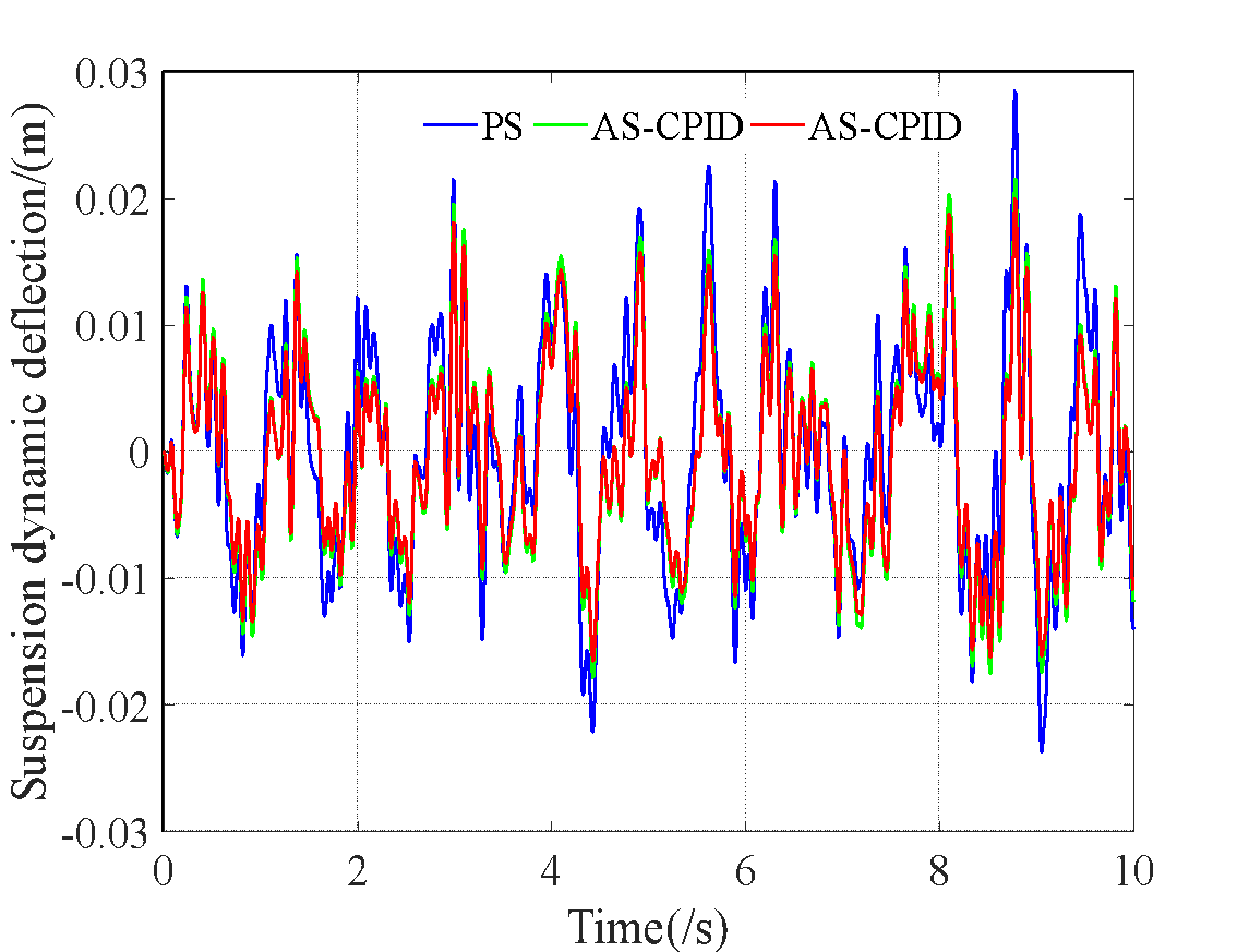
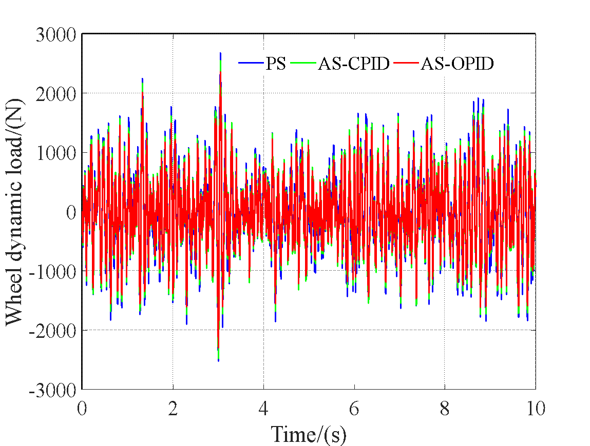
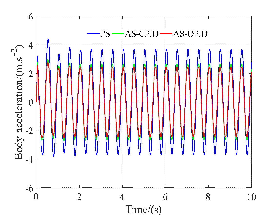
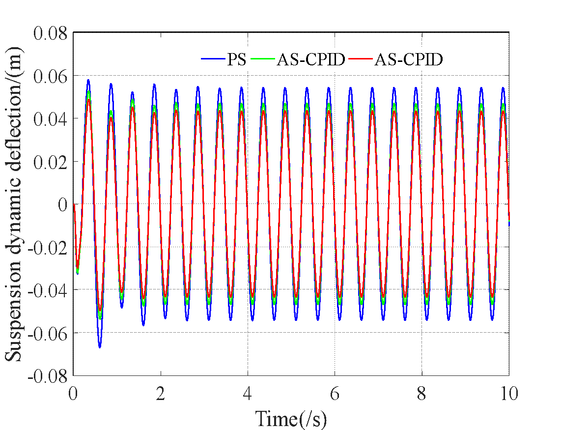
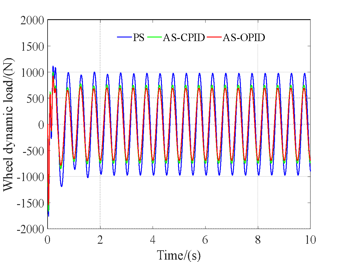
The performance of the AS system with the optimized PID controller (AS-OPID) is compared with the AS system using a conventional PID controller (AS-COPID) and the PS system in the time domain, based on the responses of the vehicle body acceleration, suspension working space, and tire dynamic load, as shown in Fig. 6, Fig. 7, and Fig. 8. Additionally, their RMS values are determined according to the ISO 2631-1 (1997) standard [41], as presented in Table 3.
RMS | Suspension type | ||||
PS | AS-CPID | ↓ (%) | AS-OPID | ↓(%) | |
BA (m.s2) | 0.8472 | 0.7037 | 16.94 | 0.6519 | 23.05 |
SDD (m) | 0.0091 | 0.0078 | 14.29 | 0.0073 | 19.78 |
WDL (N) | 693.3096 | 648.8795 | 6.41 | 601.0673 | 13.31 |
From Fig. 6, Fig. 7, and Fig. 8, it is evident that the response curves for BA, SDD, and WDL with the AS-OPID and AS-CPID controllers are significantly lower compared to the PS system. Notably, the comparison of performance indices reveals that, compared to the PS system, the BA, SDD, and WDL values with AS-CPID decreased by 16.94%, 14.29%, and 6.41%, respectively. Meanwhile, the RMS values for BA, SDD, and WDL with the AS-OPID are not only lower than those with the AS-CPID but also significantly lower than those of the PS, with reductions of 23.05%, 19.78%, and 13.31%, respectively. This demonstrates that the AS system with an optimized controller significantly improves vibration reduction, highlighting the essential role of the optimization process. The results emphasize the effectiveness of the AS-OPID controller in reducing vibrations more efficiently than the AS-CPID, leading to better vehicle stability and enhanced ride comfort.
The performance of the AS-OPID is further compared with that of the AS-CPID and the PS under harmonic road input. The time-domain responses of BA, SDD, and WDL are presented in Fig. 9, Fig. 10, and Fig. 11. The corresponding RMS values are provided in Table 4 for further analysis.
RMS | Suspension type | ||||
PS | AS-CPID | ↓ (%) | AS-OPID | ↓(%) | |
BA (m.s2) | 2.6017 | 1.8713 | 28.07 | 1.7334 | 33.37 |
SDD (m) | 0.0384 | 0.0331 | 13.8 | 0.0306 | 20.31 |
WDL (N) | 697.671 | 537.6488 | 22.94 | 498.0326 | 28.62 |
The results shown in Fig. 9, Fig. 10, Fig. 11, and Table 4 demonstrate that the time-domain responses of the AS-OPID are significantly lower than those of the AS-CPID and the PS under harmonic road input. Specifically, compared to the PS, the RMS values for BA, SDD, and WDL with the AS-CPID are reduced by 28.07%, 13.8%, and 22.94%, respectively. On the other hand, the AS-OPID achieves the highest reduction, with the RMS values for BA, SDD, and WDL decreasing by 33.37%, 20.31%, and 28.62%, respectively, when compared to the PS. These results indicate that the AS-OPID outperforms both the AS-CPID and the PS in terms of reducing BA, SDD, and WDL under harmonic road input. The higher reductions in RMS values achieved by the AS-OPID suggest that it provides superior performance in enhancing ride comfort and reducing vehicle vibrations.
This study focuses on optimizing the PID controller parameters for an electric vehicle (EV) active suspension system using the Firefly Algorithm (FA). The main conclusions drawn from the current research are summarized as follows:
An active suspension system is established based on a quarter-car model of an EV subjected to both random road excitation and harmonic disturbances. The model takes into account the increased unsprung mass. Additionally, it is designed to comprehensively evaluate the effectiveness of the active suspension system in improving BA, SDD, and WDL.
A PID controller is applied to the active suspension system, in which the controller parameters are optimized using the Firefly Algorithm. Simulation results indicate that, under random road excitation, the AS-CPID achieves reductions in RMS values of BA, SDD, and WDL by 16.94%, 14.29%, and 6.41%, respectively, compared to the passive suspension (PS). In contrast, the AS-OPID achieves even greater reductions, with RMS values of BA, SDD, and WDL decreasing by 23.05%, 19.78%, and 13.31%, respectively, compared to the PS.
Under harmonic road excitation, further improvements are observed. Compared to the PS, the AS-CPID reduces the RMS values of BA, SDD, and WDL by 28.07%, 13.8%, and 22.94%, respectively. The AS-OPID again demonstrates superior performance, achieving reductions of 33.37%, 20.31%, and 28.62%, respectively, in the RMS values of BA, SDD, and WDL.
Overall, the results confirm that optimizing PID controller parameters using the Firefly Algorithm significantly enhances the performance of EV active suspension systems. In particular, the AS-OPID consistently outperforms the conventional AS-CPID and passive systems, contributing to better ride comfort, reduced vehicle vibration, and improved stability across different types of road disturbances.
[Bui Van Cuong] was funded by the Master, PhD Scholarship Programme of Vingroup Innovation Foundation (VINIF), code [VINIF.2023.TS.018].
Van-Cuong Bui, Firefly Algorithm-Based PID Optimization for Active Suspension Systems in Electric Vehicles