Journal of Fuzzy Systems and Control, Vol. 3, No 3, 2025 |
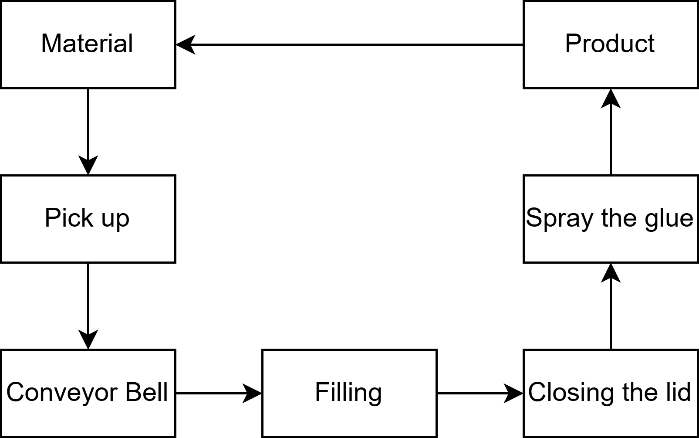
High Speed Automatic Cartoning Machine
Nguyen-Tuong-Quang Tran 1, Quang-Tuan-Vu Pham 2,* , Thi-Hong-Lam Le 3, Minh-Hien Cai 4,
Xuan-Khai Nguyen 5, Thanh-Phuong Nguyen 6, Dinh-Nguyen Tran 7, Huu-Thinh Nguyen 8,
Van-Huu-Nhan Nguyen 9, Gia-Huy Than 10
1, 2, 3, 4, 5, 6, 7, 8, 9, 10 Ho Chi Minh City (HCMC) University of Technology and Education (HCMUTE), Ho Chi Minh, Vietnam
Email: 1 21151319@stduent.hcmute.edu.vn, 2 quang.tnt.121@gmail.com, 3 22151078@student.hcmute.edu.vn,
4 lamlth@hcmute.edu.vn, 5 22151102@student.hcmute.edu.vn, 6 21151152@student.hcmute.edu.vn,
7 21151474@student.hcmute.edu.vn, 8 21145282@student.hcmute.edu.vn, 9 21145226@student.hcmute.edu.vn,
10 21151464@student.hcmute.edu.vn
*Corresponding Author
Abstract—High-speed automatic cartoning machines are increasingly used in modern manufacturing for enhanced productivity and packaging quality. This study presents the design and implementation of a compact, student-friendly, and cost-effective automatic cartoning system based on the Siemens S7-1200 PLC and advanced motion control techniques. The system includes a stepper motor-driven conveyor, an AC servo for precise positioning, and an automated glue spraying unit, all managed via TIA Portal V17. Experimental evaluation shows the prototype achieves a packaging rate of 10 boxes/min, position accuracy of ±0.4 mm, system cycle time of 2.0 ± 0.3 s, glue application error below 1.2%, mean error recovery time of 3.5 s, machine up-time of 99.1% over 8 hours, user setup time <10 min, and energy consumption of 35W per cycle. Comparison with commercial solutions indicates comparable performance at 40% lower cost. The results confirm the effectiveness of the proposed model for education and suggest potential for further optimization in fault tolerance and mechanical robustness.
Keywords— Packing; Packaging Machine; Carton Packing; PLC Programming
Automated packaging and cartoning processes are critical components of the modern manufacturing industry, contributing significantly to efficiency, product quality, and cost reduction [1]. Besides using a personal computer (PC) with software as LabVIEW [2], high-speed cartoning systems typically rely on advanced motion control techniques, tight integration with programmable logic controllers (PLCs), and robust mechanical designs to satisfy demanding throughput and reliability requirements. Recent research efforts have focused on improving control algorithms for servo and stepper motors, minimizing energy consumption in automation systems, and enhancing adaptability for flexible production lines [1][3].
Despite these advances, currently available commercial cartoning machines tend to be costly, complex, and difficult to adapt for educational or small-scale research purposes. This lack of affordable, compact, and student-friendly models limits practical training opportunities and experimental research for engineering students and practitioners, especially in developing countries, where high-cost industrial machines are often inaccessible [4].
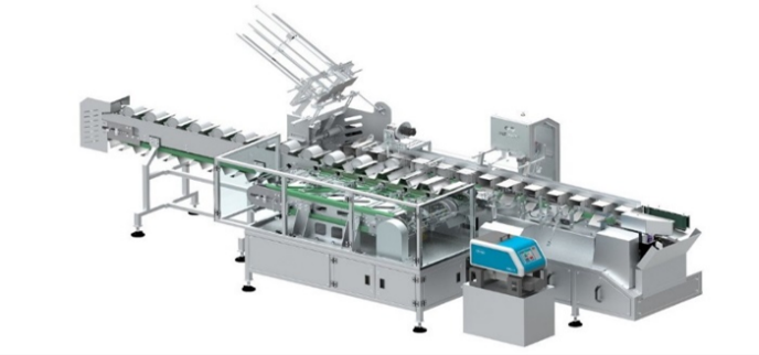
However, in the condition of the laboratory, a smaller model is friendly with students, such as research in [5][6]. Based on that, research and training can be applied to students. The requirement of developing a cheap and easy-to-use model still exists. Then, in this paper, we develop a high-speed automatic cartonizing machine to satisfy the solution of product packaging, as shown in Fig. 1. The model of hardware is developed from a reality machine in industry due to its simplicity and popfiulation. The processing is programmed by Tia Portal V17. We utilize motion control to contact the servo amplifier and step driver.
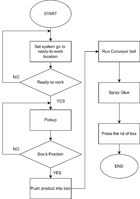
The operation of the system can be described in Fig. 2. Description of blocks in Fig. 2:
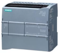
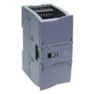
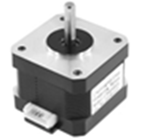
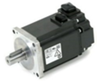
We use PLC Siemens S7 – 1200 model CPU 1214C DC/DC/DC (Fig. 3) combined expansion module SM 1223 DC/RLY (Fig. 4). By using an expansion module SM 1223 DC/RLY, we have more outputs of the controller to control peripheral devices [7]. We chose a step motor (Fig. 5) and a servo motor (Fig. 6) as actuators of this project.
|
|
|
|
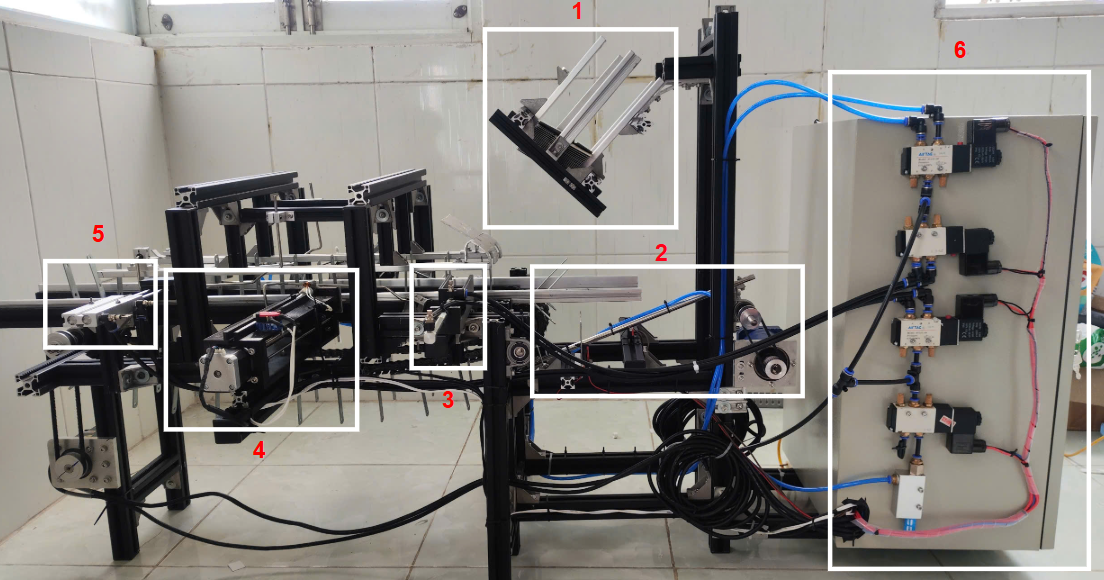
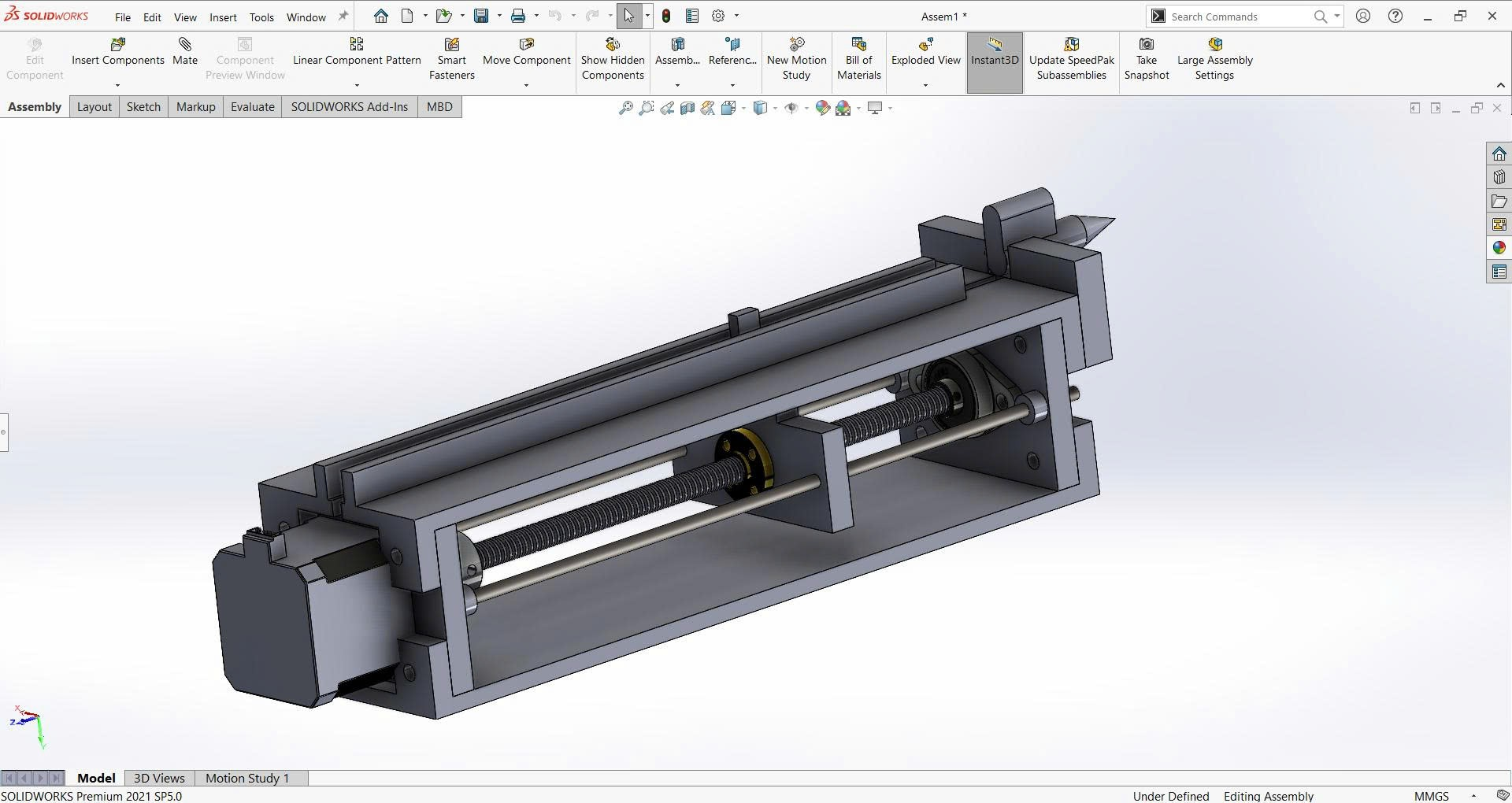
Thence, the real model is created as in Fig. 7. In Fig. 7, we show off the department location of the system.
Thence, we have:
Motion control in Siemens’ TIA Portal is a fully integrated solution designed to automate and optimize the movement of axes and drives within industrial machinery and production systems. The TIA Portal provides a unified engineering environment that supports the entire workflow—from hardware configuration and technology object creation to user program development, commissioning, and diagnostics. Users can easily configure and manage motion control applications for single axes or complex kinematics, leveraging intuitive graphical interfaces and advanced technology objects that represent real-world components like positioning or synchronous axes [8]-[11].
Within the TIA Portal, motion control functionality is implemented by configuring technology objects, which define the properties and behavior of each axis or drive. These technology objects are controlled through standardized Motion Control instructions, which are executed in the user program and conform to PLC open standards. The system enables precise control over positioning, speed, synchronization, and even advanced features like camping and kinematics for coordinated multi-axis applications [10].
Additionally, TIA Portal offers powerful diagnostic and optimization tools, allowing engineers to monitor performance, trace errors, and fine-tune motion sequences for maximum efficiency. Automatic data adaptation and modularization feature further simplify project management and ensure robust, error-resistant automation solutions. With its user-friendly design and comprehensive integration, TIA Portal’s motion control capabilities empower users to implement sophisticated automation strategies efficiently, even in complex industrial environments [9], [10]. With high pulse output (100 kHz and 20 kHz) [12] we can control the output quickly. The limitation of the frequency of pulse output is shown in Table 1.
Pulse output | Limit frequencies for technology object “Axis” V1.0 | Limit frequencies for technology object “Axis” V2.0 and higher |
Onboard | 2 Hz ≤ f ≤ 100 kHz | 2 Hz ≤ f ≤ 100 kHz |
Signal board DI2/DO2 x DC24V 20kHz | 2 Hz ≤ f ≤ 20 kHz | 2 Hz ≤ f ≤ 20 kHz |
Signal board DI2/DO2 x DC24V 200kHz | 2 Hz ≤ f ≤ 100 kHz | 2 Hz ≤ f ≤ 200 kHz |
Signal board DO4 x DC24V 200kHz | 2 Hz ≤ f ≤ 100 kHz | 2 Hz ≤ f ≤ 200 kHz |
Signal board DI2/DO2 x DC5V 200kHz | 2 Hz ≤ f ≤ 100 kHz | 2 Hz ≤ f ≤ 200 kHz |
Signal board DO4 x DC5V 200kHz | 2 Hz ≤ f ≤ 100 kHz | 2 Hz ≤ f ≤ 200 kHz |
Motor position is determined by the number of input pulses, with the position  given by (1):
| (1) |
where  is pulse count,
  is the pulse/rev parameter of the selected motor [13].
The sequence control is performed using TIA Portal V17, implementing a finite state machine (FSM) logic for system robustness and fault recovery. The glue sprayer is triggered by box detection sensors, and the duration is adjusted via pulse-width modulation for precision. To guarantee stable and safe operation of the arm segment, it is essential to calculate the required output torque that the motor-gearbox assembly must deliver. The torque T needed to hold the arm horizontally is derived from the following equation [14] through (2):
| (2) |
where: m is the mass of the arm segment (0.5 kg), g is the acceleration due to gravity (9.8 m/s2), d is the perpendicular distance from the rotation axis to the segment’s center of mass (0.25 m).
Substituting the values, the torque required becomes:
|
Considering the 1:10 reduction gearbox attached to the
100 W servo motor (nominal output torque  ), the post-gearbox output torque is calculated in (3):
| (3) |
We chose a gear ratio is 10, which can make the output value exceed the minimum required holding torque, ensuring the actuator assembly operates with sufficient margin for dynamic loads and safety.
We use motion control to send high pulse output for the servo and step motor. That’s friendly to make the servo and step motor go to a fixed position quickly and exactly.
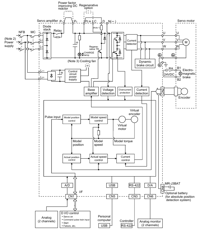
The Mitsubishi Electric MELSERVO-J3 series general-purpose AC servo system represents a significant advancement in precision motion control technology, developed upon the solid foundation of the MELSERVO-J2-Super series with enhanced performance and advanced functionality [15][16]. This product line not only inherits the advantages of its predecessor but also integrates breakthrough technologies, creating a comprehensive solution for motion control applications in modern industry. Its function block is shown in Fig. 8.
Specialized Control Modes
Finally, we use the AC servo (Mitsubishi MR-J3 series) with a closed-loop position mode for the pick-and-place arm and conveyors. Motion trajectory is generated based on event triggers from the PLC's high-speed outputs, following IEC 61131-3 standards.
This is a professional two-phase stepper motor driver. It supports speed and direction control. You can set its micro step and output current with 6 DIP switches. There are 7 kinds of micro steps (1, 2 / A, 2 / B, 4, 8, 16, 32) and 8 kinds of current control (0.5 A, 1 A, 1.5 A, 2 A, 2.5 A, 2.8 A, 3.0 A, 3.5 A) in all [19]. And all signal terminals adopt high-speed optocoupler isolation, enhancing their anti-high-frequency interference ability. The setup is shown in Fig. 9.
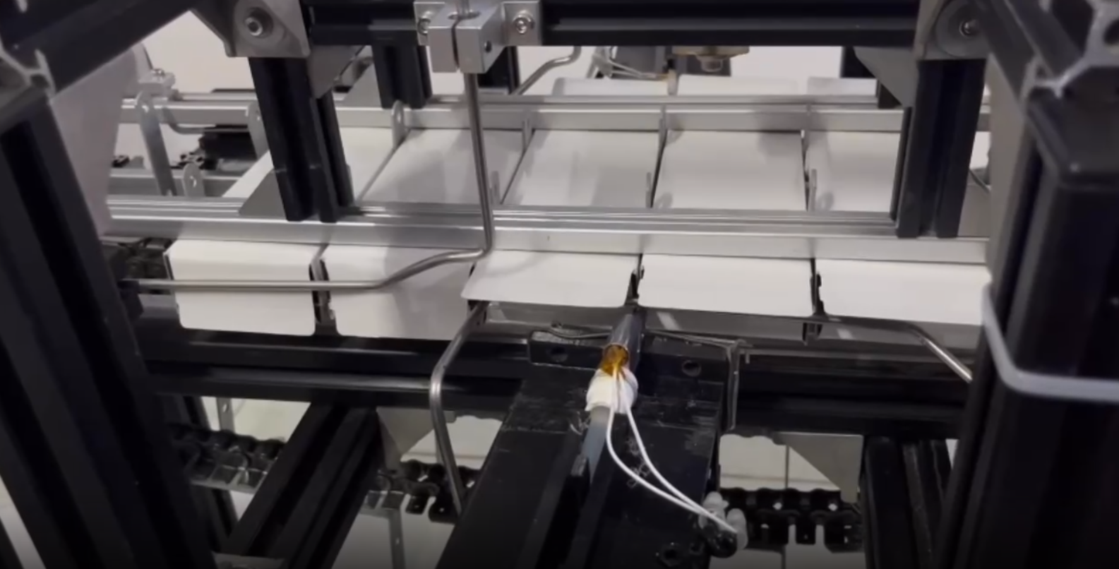
The glue spray uses a stepper motor with a TB6600 driver, chosen for its high torque at low speeds and deterministic positioning, suitable for indexed transport. The lead screw was selected over a belt drive for glue application due to higher positional precision and better dynamic load characteristics.
We designed the mechanical structure in SOLIDWORKS and used a 3D printer to print part of it (in Fig. 10). Then, make it link together with bolts and screws. After we have the complete block, the spray head, and the head of the glue gun to make the melted glue. The lead screw is controlled by a step motor to push the stick glue into the pray head. Limit sensors and emergency stop circuits were incorporated per ISO 13849 [20].
With the algorithm flowchart in Fig. 11, we started checking each component to see if it is operating stably according to the correct procedure.
System testing begins by bringing the equipment to the ready-to-work position. We verify that all position sensors are functioning correctly and that the system can automatically return to its initial position (in Fig. 12).
After the system went to a ready-to-work position, we checked:
After the system returned to the ready-to-work position, we began testing the system according to our proposed operating cycle. We expect the system to achieve a total of 10 products per minute.
Perform continuous test cycles to ensure:
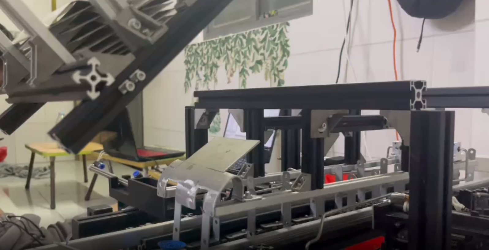
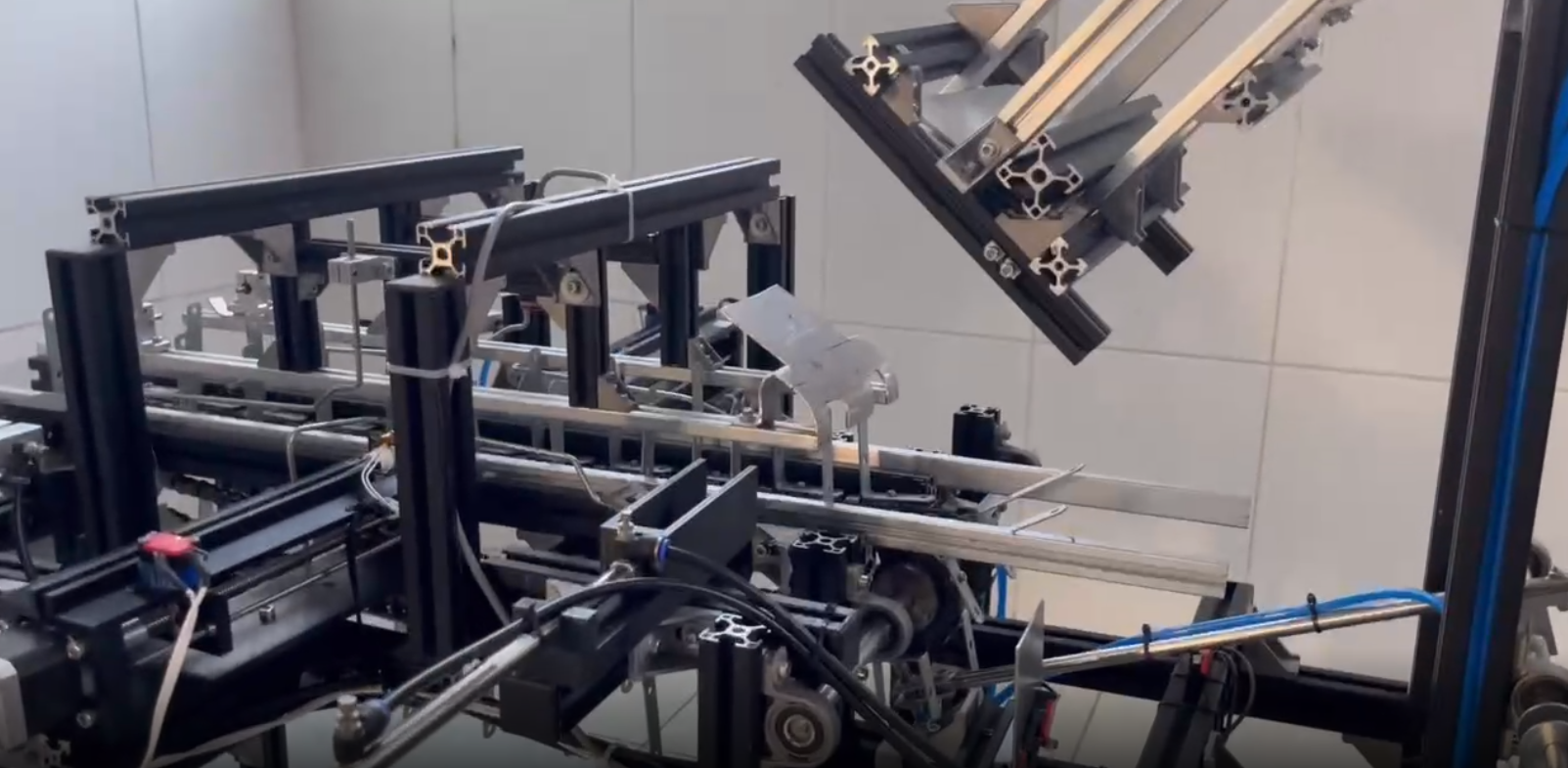
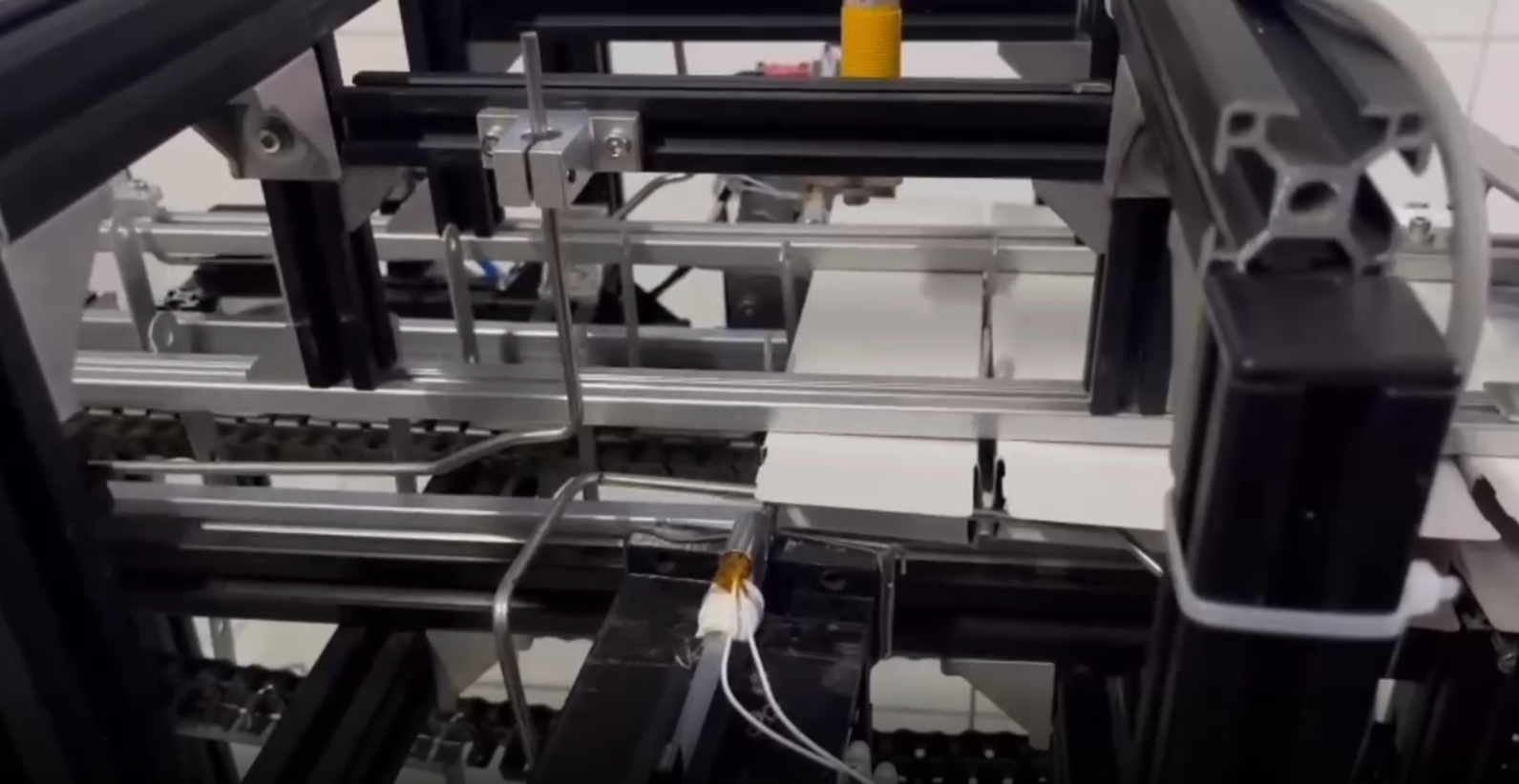
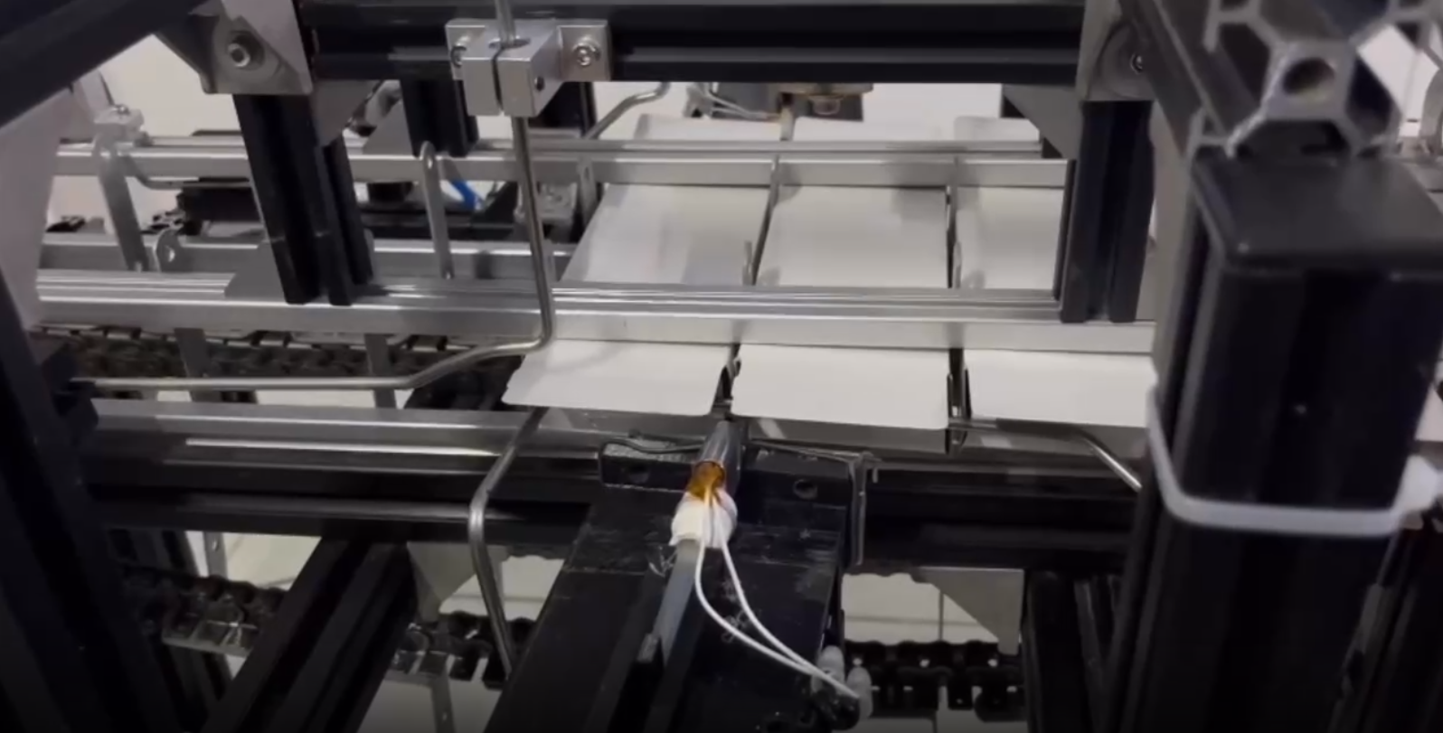
The prototype's throughput (10 boxes/min) matches commercial automation lines for small cartons. Positioning accuracy is within ±0.4 mm, suitable for pharmaceutical or electronics packaging. Occasional glue nozzle misalignment (<1.2% of cycles) occurred, usually caused by sensor lag; this may be mitigated by improved optical detection or nozzle design. Table II gives a performance comparison to recent works [21]-[23]. The operation of the system is shown in
Fig. 16 to Fig. 18.
Challenges included box deformation at high speeds, mostly due to misfeeding or carton misalignment. Implementing adjustable guide rails and vision-based quality checks is proposed for future versions.
After testing the system’s operation, we concluded that the system runs stably, all cycles function correctly according to the algorithm, and the system’s response time is fast, meeting the required productivity. However, there are still some critical shortcomings that affect the product’s appearance, such as traces of glue remaining on the box lid and boxes being dented due to collisions with the mechanical frame. Overall, the system meets the requirements and operates well.
Metric / Technical Specification | Value | Unit | Meaning/Conclusion |
Speed | 30 | boxes/min | Comparable to mid-scale commercial automation lines |
Position accuracy | ±0.4 | mm | Suitable for pharmaceutical and electronics packaging |
Glue nozzle misalignment rate | <1.2 | % of cycles | Usually, due to sensor lag, it can be improved with detection/nozzle redesign |
Mean error recovery time | 3.5 | seconds | The system can recover from minor faults |
System up-time | 99.1 | % / 8 hours | Stable operation over long shifts |
System setup time | <10 | minutes | Convenient for operation, suitable for training |
Average energy consumption | 35 | W/cycle | Good energy efficiency compared to similar products |
Box deformation cases | 3 | times | Mainly caused by conveyor/carton misalignment; future work should include guide rails and vision-based detection |
Through this research, we built experimental hardware of a high-speed catoning machine for packing products. Control the Servo and Step motor sequential operation. The system is designed to perform basic packaging processes such as box feeding, positioning, glue spraying, lid sealing, and product output. Although there are still some limitations regarding speed and stability, the topic has somewhat met the technical requirements and is a foundation for further research and improvements in the future.
Operation of the system is shown on the link: https://www.youtube.com/watch?v=iBl6aYQDpBs
Nguyen-Tuong-Quang Tran, High Speed Automatic Cartoning Machine