Journal of Fuzzy Systems and Control, Vol. 1, No 3, 2023 |
The Use of Vacuum to Increase the Effectiveness of X-Ray Tube Maintenance
Alya Izzaty Bika 1,*, Meilia Safitri 2, Erika Loniza 3, Bagus Roni Yusuf 4, Djoko Sukwono 5
1,2,3,4 Department of Medical Electronics Technology, Universitas Muhammadiyah Yogyakarta, Yogyakarta, Indonesia
5 CV Sehat Sejahtera, Yogyakarta, Indonesia
Email: 1 alya.izzaty.vok19@mail.umy.ac.id, 2 meilia.safitri@vokasi.umy.ac.id, 3 erika@umy.ac.id,
*Corresponding Author
Abstract—Each device requires redundancy, including the X-ray machine. In an X-ray machine, there is an important component as the location for the creation of X-rays, namely the X-ray tube. This tube needs routine maintenance to increase the tube's lifetime. In addition, maintenance that was originally done manually, with this device can be done automatically and more quickly. In addition, maintenance that was originally done manually can be done automatically and faster with this device. X-ray tube oil vacuum is used as an effective solution for the maintenance of an X-ray tube machine that lasts for days. This device comes with easy use, equipped with two buttons and a display. This device can increase the productivity of both the device and the technician itself. The application of the use of X-ray tube oil vacuum is intended for hospitals and health facilities that have active X-ray machines. This device has been able to be built. Based on the results, it has a 2.5% error for the measurement at minimum and maximum pressure and a 3% error at -15 KPa pressure. The volume of the X-ray tube fully filled is always the same for each measurement. It can be concluded that this device can be effective in time because it only takes minutes to fill the X-ray tube up to full. Still, many parts can be improved and developed, such as the size and the weight.
Keywords—X-ray tube; Maintenance; Vacuum; Automatic
One of the points on the sustainable development goals is point number 9, industry, innovation, and infrastructure. The expected targets from these points include strengthening scientific research and encouraging innovation in 2030. This target point is also expected to increase access for industry and small-scale companies so that they can be sustainable in adopting better technology. One of the ways to support the achievement of this target is by technological developments which are also accompanied by the ongoing pandemic. The medical device technology is increasing rapidly, and this increase is also being felt in Indonesia. This health technology is forced to adapt to the latest needs. Medical devices help doctors side by side with the results of a diagnosis made by a doctor. This technology is so important, especially in a pandemic [1]-[2]. The medical device technology that is currently being developed is an X-ray machine [3]. X-ray machine plays an important role during this pandemic because they can see the condition of organs that cannot be seen directly by the naked eye [4]-[5]. This is done to obtain accurate diagnostic results and prevent errors from occurring by conducting a thorough examination.
An X-ray machine is one of the requirements that must be met in certain examinations. It is used to carry out medical diagnoses that utilize X-rays. The X-ray beam will penetrate the body part being irradiated and the X-ray emitted from the tube is directed at the patient's body part to be diagnosed [6]-[7]. The results of the emitted X-ray beam are then captured by the film and will produce an image file of the object, and the image file will be used as material for diagnosing the patient's disease.
The X-ray tube is one of the components in the X-ray machine where the X-rays are created. The X-ray tube functions to create X-ray photons from the electrical energy supplied by the X-ray generator [8]. The X-ray tube components include cathode and anode assemblies, rotor and stator (for rotary anode systems), as well as tube housings [9]. Damage to the X-ray tube is usually caused by the oil in the tube not hitting the entire inner surface of the tube resulting in a fire inside the tube due to the high voltage used as its supply power [10]. The oil in the tube functions as a lubricant and coolant, when the oil does not cover the entire inner surface of the tube, the heat generated will immediately burn the component [11]-[13]. The creation of X-ray photons that can be generated is only 1% while the remaining 99% is converted as heat. Therefore, the role of oil, in this case, is very important. This crucial component can be seen in Fig. 1.
Among many health technologies produced, Indonesians have contributed to the development of health technology in Indonesia. CV Sehat Sejahtera is one of the nation's subsidiary companies that produce medical devices, especially in the field of Radiology. This CV was formed in 2004 and is located in the Sleman Regency area, Yogyakarta. CV Sehat Sejahtera has obtained a standing permit according to the decision of the Sleman District Court Registrar on October 6 2006 with number cun.07.01.266.CV.2006. Apart from being a medical device manufacturer, this CV also accepts maintenance of Radiology equipment, especially X-ray machines. In carrying out maintenance of X-ray machines, this CV encounters obstacles, one of which is that this machine cannot work due to damage to the X-ray tube parts (Djoko Sukwono, when interviewed on December 7th, 2021).
Incorrect oil filling can cause the tube to burn. In addition, there are still not many studies that discuss this. In a study that explored and identified damage to X-ray machines, it was found that there was a high tendency for damage to the tube [14]. The research found that damage can be minimized using a systematic sequential method. This method is a test method by collecting performance data in determining damage. This activity is the same as maintenance or equipment maintenance. Machine tubes are periodically checked and tested.
In X-ray tube maintenance, is still done manually to fill the tube oil. Filling this oil takes up to one week for the oil to completely cover the entire inner surface of the tube. This is caused because the density of oil is different from water and the viscosity level of oil is also higher, so a vacuum is needed to remove the air in the tube so that it can be covered by oil [7], [15]. The level of effectiveness of the time used is also getting better because the technician does not need too long to complete the maintenance of the tube. According to a technician from CV Sehat Sejahtera, it takes at least one week to maintain an X-ray tube without a vacuum process. In addition, if the tube is not maintained, the lifetime of the tube will shorten, so the application of this oil vacuum device will increase its productivity.
In the formulation of development targets have SMART characteristics, namely as follows.
The main purpose of making an X-ray tube oil vacuum is as a maintenance medium for X-ray tubes that can fill oil automatically and efficiently. Filling oil can be done manually, but this is not effective, so it is necessary to create an innovative device to increase the work efficiency of technicians and X-ray machines. This innovation can be said to be automatic because it utilizes programming technology to carry out every function and command on the device. This will further reduce the number of technicians working with manual oil filling. Filling this oil must also be done in a vacuum so that no air enters the tube. Air in the drum can harm the drum when in use. The use of vacuum has been widely carried out in the gas industry and can work well [16]. Of course, this can be applied by adding innovation to other things like this device. By using good materials and without leakage, the device will work properly and get the maximum value [9]. In addition, it is equipped with a pressure sensor as a safety so that the pressure in the device while working can be monitored [10] and a cylinder full level indicator which will automatically turn off the device function when the indicator shows full level. With efficient maintenance, X-ray machines can also be put back into service more quickly. These innovations will make the device user-friendly, easy to use, and secure.
To guarantee the function of the device, measurement of pressure, lighting on the vacuum box, and the level of fullness of the cylinder are carried out to obtain values for data analysis and calculation of the average and deviation of errors. This test will also be carried out at the CV Sehat Sejahtera workshop accompanied by technicians and experts to get the device to function optimally and meet radiological eligibility standards. In addition, this device will be calibrated so that its feasibility can be determined. After carrying out the function test, the device will also be evaluated and developed. This aims to minimize errors and deficiencies that exist as low as possible.
The use of negative compressed air has been done a lot and is safe. The material design of the device also needs to be considered so that the vacuum or negative compressed air works effectively and does not damage the tube. Materials that can be used for the vacuum method are steel and iron with high-density levels, namely 8 gr/cm3 and 7.7 gr/cm3. In addition, a pressure sensor is also used to determine the pressure in the device so that its condition can be monitored. Its use is also easy and automatic.
Based on the problems stated regarding the importance of an X-ray tube filled with oil and a vacuum, an X-ray tube oil vacuum is needed can fill the tube as well as vacuum so that the oil can be completely in the tube and the tube is in a vacuum. In addition, the manufacture of this device also uses materials and equipment that are easy to find on the market. Some of the main materials needed in making this device are Arduino, a compressor, and the MPXV4115V pressure sensor. besides that, two buttons make it easy for the user and the display uses a 16 2 character LCD. The microcontroller used is also open source so it is easy to use, namely Arduino.
The X-ray tube oil vacuum manufacturing process is expected to be completed in several months depending on how long the process will be developed. Starting from the mechanical design process of the device, including the devices and materials used, followed by creating a schematic and device layout. After the required modules and drivers have been made, it is continued with program development and function testing. Evaluation and improvement are carried out after carrying out functional tests so that data on deficiencies and material for device development are obtained.
To increase the value of the effectiveness of X-ray tube maintenance, we need a device that can replace the task. This result will be faster than normal maintenance. Technician productivity levels can also increase. Filling oil in the X-ray tube can be done manually as is generally done, but it takes a relatively long time, up to days or even up to a week. This is done so that the oil covers the entire inner surface of the tube, which is the insert tube. Oil is used as an insulator and coolant so that tubes that receive high voltage can remain in good condition. This oil must also cover the entire surface without air because air can trigger a burning tube. This must make the tube become damaged. The innovation of this device lies in the process of automatically filling the X-ray tube. Apart from being automatic, this device can also streamline the maintenance process itself by shortening the oil filling time without air gaps. In addition, this device is easy to use, by simply pressing a button, the device can work automatically and ensure that there is air in the tube because during the process it uses negative compressed air or vacuum.
The main stage as an effort to achieve targets begins with a literature study and outreach to CV Sehat Sejahtera as has been implemented. After finding the problem and solving it, the preparations for making the device continued. In making this device, the design of the devices and materials used will be carried out. After determining the equipment and materials, then do the schematic and layout. The finished schematics and layouts will become modules and drivers. The modules and drivers referred to here are the power supply, microcontroller circuit, pressure sensor circuit, and compressor driver. Then proceed with making a program that will be included in the microcontroller. The program is made using the Arduino IDE. Arduino was chosen because this microcontroller is open-source and easy to obtain. After the device is ready, a function test is carried out at the CV Sehat Sejahtera workshop. This function test will produce data for analysis. After the analysis process is complete, the final stage will be carried out, namely evaluation and development. This is intended so that the device can work and be used properly at the CV or the X-ray machine maintenance service provider's place.
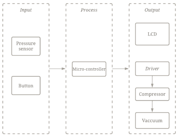
Fig. 2 is the block diagram of X-ray tube oil vacuum that will increase the effectiveness of X-ray tube maintenance process.
The work system of this device is divided into three, namely input, process, and output. Input from this innovation device comes from the button pressed. The button referred to here is the 'start' button which then gives orders to be processed to the microcontroller so that the device can work. This innovative device works by transmitting commands from the microcontroller to the driver which is followed by the compressor running to create a vacuum. As the vacuum space is created, oil will also flow into the X-ray tube. When the oil level indicator is detected, the oil filling and vacuuming process will stop automatically. There is also a 'stop' button which can be used as a button to stop the process manually. In addition to getting input from the buttons, when the device is working, the microcontroller also receives commands from reading the pressure sensor on the device. This reading value is processed in the microcontroller and displayed on the 16 2 character LCD screen.
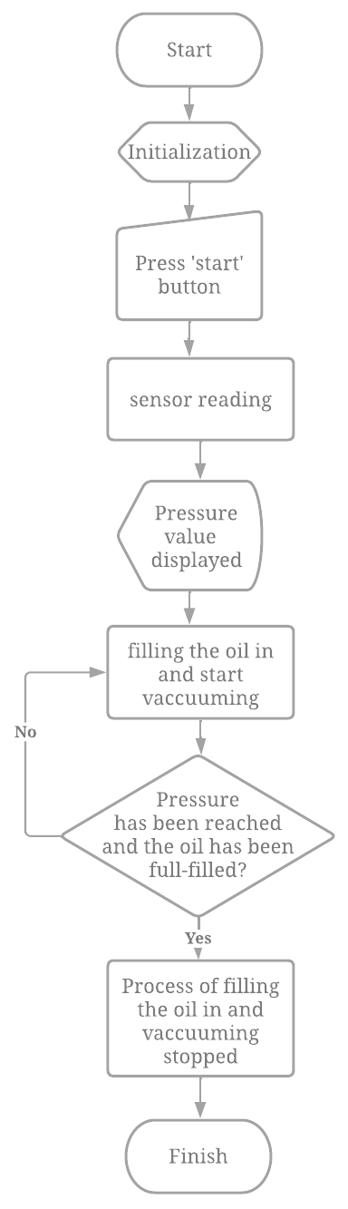
From the design of the device that has been done, the flow chart in Fig. 3 is obtained as a research process so that the device can work.
The flow function of the device can be seen from the start process followed by program initialization. After the initialization process is complete, the 'start' button is pressed, and the device will start working. The device works by creating a vacuum chamber using a compressor and filling oil into the X-ray tube. The pressure in the vacuum chamber is also read so that it can be controlled. The reading value of this pressure sensor is displayed on the character LCD. After the oil filling process is reached, the process will stop. The device will continue to work until the oil condition is full and reaches its pressure. The process that stops indicates the work of the device has been completed.
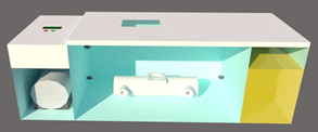
Fig. 4 is the mechanical diagram of the X-ray tube oil vacuum. The X-ray tube oil vacuum design uses 3 rooms with the main room as a place to place the X-ray tube for maintenance. The other two rooms are where the oil and the compressor are stored. At the top, there are buttons and a display in the form of a character LCD. In addition, there is a kind of window to peek at the processes in the main room. In this study, a steel plate with a thickness of 3 mm was used to create a vacuum without being damaged or curved inward.
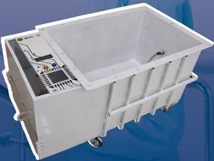
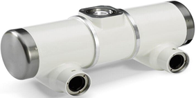
Fig. 5 is the result of the device view of the X-ray tube oil vacuum that has been built. The result is not fully like the mechanical diagram that has been planned. It can happen because of many factors, such as the size of the compressor, which is bigger than expected, and the oil storage that is unlikely placed beside the main room. It has a 70  40 40 cm dimension. It can work at -10KPa up to -15KPa. It has a small and openable compartment under the circuit to place a small compressor. This device works on 220 VAC and has 4 wheels to make it easy to move. Outside bones are also built to make sure the body structure will not curve inward besides it is also built in a 3 mm steel plate. To seal the vacuum, this device uses rubber on the top as a cap. It also has a window from thick glass that can see through the filling oil process.
The test results at minimum and maximum pressure of the device can be seen in Table 1. The minimum pressure setting is -10KPa and -15KPa for the maximum one. The comparison device used is DPM-4 and MPXV4115V is used for the pressure sensor. Time and volume also become the variables for making sure this device can accelerate the time with consistent volume. Volume measured is how much the X-ray tube can be filled based on the indicator level. This test is held to measure the exact reading of the setting, the comparison device that has been calibrated, and the pressure sensor reading used.
From Table 1, it can be known that the bigger the pressure it works, the faster the oil is filled fully. The volume of oil that is filled is also consistent. It means that although the pressure is getting bigger and bigger, it will not interrupt the filling oil process so that the volume filled is always the same. The highest deviation and error from this test are in -0.4 KPa and 4%. The average error from this test is 2.5% and can still be categorized as normal or good.
Pressure Setting (KPa) | Time (minute) | Pressure Measurement (KPa) | Error | Volume (L) | ||
Comparison Device | Sensor Reading | Deviation | ||||
-10 | 18’40” | -10.0 | -9.7 | -0.3 | 3% | 3.41 |
-11 | 18’17” | -11.2 | -10.8 | -0.4 | 4% | 3.41 |
-12 | 17’36” | -12.0 | -11.9 | -0.1 | 1% | 3.41 |
-13 | 17’19” | -13.0 | -12.8 | -0.2 | 2% | 3.41 |
-14 | 16’28” | -14.1 | -13.7 | -0.4 | 4% | 3.41 |
-15 | 15’10” | -15.0 | -14.9 | -0.1 | 1% | 3.41 |
Table 2 shows the test results at -15 KPa. As the test before, it still uses DPM-4 for the comparison device and MPXV4115V as the pressure sensor. This test also measures the volume that is fully filled in the X-ray tube based on the indicator level on the research device. Here -15 KPa is used because it takes the shortest time based on the previous test and is still safe for the device without being curved inward. It takes 10 times of measurements to make sure the value and get the nearest accurate value.
Pressure Setting (KPa) | Time (minute) | Pressure Measurement (KPa) |
|
| ||
Comparison Device | Sensor Reading | Deviation | ||||
-15 | 15’10” | -15.0 | -14.7 | -0.3 | 3% | 3.41 |
-15 | 15’7” | -15.2 | -14.8 | -0.4 | 4% | 3.41 |
-15 | 15’6” | -15.0 | -14.9 | -0.1 | 1% | 3.41 |
-15 | 15’19” | -15.1 | -14.8 | -0.3 | 2% | 3.41 |
-15 | 15’18” | -15.1 | -14.7 | -0.4 | 4% | 3.41 |
-15 | 15’11” | -15.0 | -14.9 | -0.1 | 1% | 3.41 |
-15 | 15’8” | -15.3 | -15.0 | -0.3 | 3% | 3.41 |
-15 | 15’17” | -15.2 | -14.8 | -0.4 | 4% | 3.41 |
-15 | 15’0” | -15.1 | -14.5 | -0.6 | 6% | 3.41 |
-15 | 15’10” | -15.0 | -14.9 | -0.1 | 1% | 3.41 |
Average | 15’11” | -15.1 | -14.8 | -0.3 | 3% | 3.41 |
Based on Table 2, informs that the volume of a fully filled X-ray tube is always the same for 10 times measurements, but it has a little deviation in time. The longest time it takes is 15 minutes 19 seconds and the shortest one is 15 minutes. It is just 19 seconds difference, and the average time is 15 minutes 11 seconds. The highest deviation from this test is -0.6 KPa or 6% error. There is still a gap between the comparison device and pressure sensor reading, which is -0.3 KPa or 3% error. It still can be categorized as good, but some improvement and development are needed so that the error can be decreased.
Many factors make any gaps between the hypothesis and the results. This has been discussed and evaluated with the technician in CV Sehat Sejahtera. Before making the outside bone, the device has been tested and got damaged or curved inward, so that outside bone is needed to prevent it. The curve can also be caused by the high pressure. Before using -15 KPa as the maximum pressure, -20 KPa has been tried and made the device curved inward. Furthermore, this device has up to 30 kilograms weight which makes it not mobile-friendly. Since steel plates are used as the base material, a heavy weight is unavoidable. in order to make mobility easier, the wheels are installed. Due to the dimensions and the weight, this device cannot be easily taken on a long-distance move. There is no exact pressure in the use of an X-ray tube oil vacuum. That is why the pressure used here is in a range of -10 KPa up to -15 KPa. This vacuum process is used to increase the effectiveness of time, in other words, make it faster and still on a consistent volume that is fully filled.
X-ray tube oil vacuum is used as an effective solution for the maintenance of an X-ray tube machine that lasts for days. This device comes with easy use, equipped with two buttons and a display. This device can increase the productivity of both the device and the technician itself. The application of the use of X-Ray Tube Oil Vacuum is intended for hospitals and health facilities that have active X-ray machines. In addition, this device can also be used by companies providing maintenance services for medical devices, especially X-ray machines.
In making this device, the design of the devices and materials used will be carried out. After determining the equipment and materials, then make a schematic and layout to become a module and driver. Then proceed with programming. After the device is ready, a function test is carried out at the CV Sehat Sejahtera workshop. The final stage is evaluation and development. The process of handling this problem requires the manufacture of a product, which is in the form of a device. Making devices requires the availability of materials and equipment that are quite expensive. Starting from vacuum compressors, Arduino as a microcontroller, device frame materials, to other small components. However, the availability of CV Sehat Sejahtera as a partner makes it easier and facilitates research and actualization of device making. This CV can help get what is needed validly. Internet access also facilitates the search for references. Devices and materials are also easy to find along with advances in technology.
This research was fully supported by Department of Medical Electronics Technology Muhammadiyah University of Yogyakarta and CV Sehat Sejahtera as a collaborator.
Alya Izzaty Bika, The Use of Vacuum to Increase the Effectiveness of X-Ray Tube Maintenance