Journal of Fuzzy Systems and Control, Vol. 3, No 3, 2025 |
A Study of Autonomous Mobile Robot
Nam-Long Doan 1, Viet-Thinh Dao 2,*, Hoang-Ha Nguyen 3, Pham-Kien-Quoc Luong 4, Tran-Thanh-Thuy Nguyen 5,
Quang-Thuan Ho 6, Thai-Duong Nguyen 7, Khanh-Dang Nguyen 8, Binh-Hau Nguyen 9, Anh-Duc Nguyen 10,
Phuong-Quang Nguyen 11, Viet-Khoi Vo 12, Van-Dong-Hai Nguyen 13
1, 2, 3, 4, 5, 6, 7, 8, 10, 11, 12, 13 University of Technology and Education (HCMUTE), Ho Chi Minh City (HCMC), Vietnam
9 Posts and Telecommunications Institute of Technology, Ho Chi Minh City (HCMC), Vietnam
Email: 1 20143046@student.hcmute.edu.vn, 2 20151413@student.hcmute.edu.vn, 3 21142521@student.hcmute.edu.vn,
4 22142042@student.hcmute.edu.vn, 5 21151433@student.hcmute.edu.vn, 6 21146156@student.hcmute.edu.vn,
7 21161439@student.hcmute.edu.vn, 8 21146084@student.hcmute.edu.vn, 9 haunb@ptit.edu.vn,
10 22142518@student.hcmute.edu.vn, 11 quangnp@hcmute.edu.vn, 12 22145180@student.hcmute.edu.vn,
*Corresponding Author
Abstract—With the rapid development of Industry 4.0, automation in production and operations is an important factor to optimize the production process. One of the most important technologies is autonomous mobile robots (AMR). The use of AMR in factories, workshops, and warehouses is becoming more and more popular. Flexibility in production helps companies better meet customer needs and increase productivity without incurring costs and wasting resources. In this study, we present the design and fabrication of an AMR vehicle system for factory environments. The system is developed on Ubuntu and the robot operating system (ROS). Innovation of AMR in our project is to emphasize the change when integrating a ROS-based distributed architecture, in which a separate embedded controller (Raspberry Pi 4 embedded computer) handles real-time control, and a localization and mapping (SLAM) task processor, along with the Navigation Stack package, is used for remote mapping and navigation. Industrial floors are often full of obstacles, so a powerful LiDAR filter and a robust SLAM pipeline are needed to improve mapping accuracy and collision avoidance. This is certainly a promising solution, while current research on autonomous mobile robots usually focuses on navigation and does not incorporate mechanical lifting mechanisms for material handling, we also improve the communication protocol to enhance system performance. Experiments show that the system can automatically position, meet scalability, improve real-time performance, and enable robots to lift/lower objects within the same ROS system, which is suitable for real-world warehouse and factory applications.
Keywords—Autonomous Mobile Robot; ROS; SLAM; Navigation; Industry 4.0; Smart Factory
With the rapid development of the 4.0 industrialization era, internal automation plays a crucial role in optimizing the supply chain, especially in factories, warehouses, and distribution centers. Autonomous robots are capable of moving on predetermined or undefined trajectories, operating in many different environments and spaces. The application of autonomous robots in factories, manufacturing plants, and warehouses is increasingly popular. Traditionally, most wasted warehouse expenses come from the logistics of moving material from one point to another, and it is exhaustive for humans to continuously walk those distances while carrying a load [1]. Flexibility in production enables businesses to respond quickly to customer needs and increase production system productivity without incurring excessive costs or consuming too many resources. traditional automated guided vehicles (AGV) follow fixed paths (for example, using magnetic wires or painted lines) and need careful infrastructure modifications; this limits their flexibility in dynamic environments. With recent advances in computing power and artificial intelligence, indoor positioning and autonomous navigation for mobile robots have been widely applied. AMR does not move along a fixed path, as is the case with AGV, but rather moves to any accessible and collision-free point within a given area [2].
One key driver of this evolution is the integration of machine learning (ML) and artificial intelligence (AI) techniques, exemplified by the deployment of deep neural networks that empower robots to learn and enhance their decision-making processes over time. This infusion of AI has significantly enhanced the adaptability of AMR to diverse and dynamic environments, resulting in more robust obstacle-avoidance strategies [3]. Machine learning algorithms allow robots to continuously learn and improve their performance over time, enhancing mapping and decision-making capabilities [4]. A core enabling technology is simultaneous localization and mapping (SLAM), which allows a robot to simultaneously build a map of unknown space and localize itself within that map. For industrial deployments, researchers have proposed multi-LiDAR and multi-modal SLAM frameworks that fuse data from several LiDAR types (spinning, solid-state, LiDAR-camera) to produce more robust and accurate maps [5].
Although numerous recent studies in AMR localization and mapping have made significant progress, most of these implementations are limited to single embedded computers for all processing, and very few systems integrate a distributed ROS architecture with the lifting mechanism, which restricts their adaptability and practical application in industrial environments. Therefore, designing a modular AMR that separates the embedded control (Raspberry Pi/MCU) from the heavy SLAM processing (stationary computer), integrates robust LiDAR and SLAM filtering, and includes a ROS-mediated loader is one of the key issues we want to improve in our research topic. Judging from previous studies of using only one embedded computer (single board or similar) to handle all processes for system (SLAM, sensor fusion, navigation, control), these designs are simple but create many limitations: the embedded board can become CPU/GPU-bound when modern SLAM and perception modules run, causing latency, reduced map quality, and poor real-time behavior under heavy sensing loads. Empirical and survey studies show that embedded implementations of SLAM face strong trade-offs between accuracy and real-time performance [6]. Distributed software architectures (separating light real-time control on an embedded MCU/board from heavy mapping or learning workloads on a more powerful host) have clear advantages for modularity, maintainability, and scalability. Recent surveys point out that modern ROS tools support distributed nodes and better real-time patterns, but many published AMR case studies still show monolithic, single-board deployments rather than a distributed ROS architecture that offloads heavy tasks to external compute nodes [7]. In our research, we found that mapping accuracy on real-world industrial floors (multiple obstacles, dynamic objects) benefits from multi-sensor fusion and LiDAR filtering. We therefore apply SLAM using multiple 2D LiDAR and fusion strategies to improve robustness and map quality, demonstrating the value of heavier processing and careful data filtering—tasks that are typically better run on dedicated computers rather than on low-power embedded boards. This gives practical
motivation to separate SLAM/map building from embedded control [8], [9].
In this topic, we focus on improving new features for AMR autonomous vehicles on optimal solutions for communication systems from previous studies. Providing solutions that are suitable for current industrial operation requirements. Instead of just processing everything on an embedded computer, we propose a modular AMR tailored for intralogistics and industrial environments. In our architecture, a Raspberry Pi 4 acts as the ROS master node, while a fixed high-performance computer handles SLAM and map construction. We incorporate LiDAR data filtering techniques to enhance mapping accuracy in environments crowded with obstacles, and the Navigation Stack with cargo lifting. Our system enables the robot to navigate flexibly, avoid collisions, lift payloads, and assist human workers in material transport tasks.
In this study, an AMR model is designed and implemented using the robot operating system (ROS). ROS is chosen because it provides many libraries and tools useful for robot development, including navigation, localization, and communication between different modules. Recent studies have shown that ROS offers numerous ready-to-use libraries and tools that help developers build robots faster and more reliably. ROS provides a modular navigation stack that integrates essential components, such as SLAM, localization, global path planning, and obstacle avoidance, forming the foundation for applications including service robotics and autonomous driving [10]. The ROS messaging and node model provide a structured communication layer across heterogeneous hosts, enabling modules such as control, perception, and planning to run on separate machines while exchanging messages seamlessly [11]. Improvements in ROS add better support for distributed systems and more robust middleware, which helps when parts of the system run on embedded controllers and other parts run on remote processors. Many application reports and experiments show ROS used in real AMR platforms for warehouse navigation, restaurant robots, and precise tasks like elevator handling. For these reasons, ROS is a practical and flexible choice for AMR development when navigation, localization, and reliable inter-module communication are needed [12], [13]. Our AMR model consists of two main parts: the hardware system and the software system. The hardware includes a mobile platform, sensors such as LiDAR and cameras, and a computing unit. The software is developed on ROS to control motion, process sensor data, and perform path planning. Our robot uses a differential drive model, a frame/chassis design with Mecanum wheels (Ommi 4 wheels), and a kinematic model that relates the wheel velocity to the linear velocity and rotation angle of the robot body (forward/backward kinematics). This is the basis for converting the body velocity commands into signals set for each motor. Some previous studies have also employed fuzzy control and nonlinear control for simple mobile robots, such as wire-following robots and two-wheeled self-balancing robots [14]. These robots can move and balance, but they are not as flexible as our approach. Recent studies have shown that Mecanum wheels provide robots with high flexibility and smooth motion in all directions, using independent PID controllers for each wheel/motor line to achieve the desired speed [15]. The robot can move forward, backward, sideways, and rotate without changing the body orientation. This makes the Mecanum wheel system well-suited for industrial spaces and transport facilities where high motion control is required. Sensor data are used for mapping and localization in indoor environments. The ROS navigation stack is applied to generate safe paths and avoid obstacles. The system is designed to be modular, so components can be easily expanded or replaced as needed. This model allows the robot to move flexibly in factory environments, perform transportation tasks, and assist workers. The use of ROS makes the AMR more reliable, reusable, and suitable for both research and practical applications.
SLAM is a method used for autonomous vehicles that lets you build a map and localize your vehicle in that map at the same time. SLAM algorithms allow the vehicle to map out unknown environments [16]. To achieve this, robot usually uses LiDAR sensors together with data from other sensors such as encoders and IMU to determine its position, movement direction, and obstacles. Among common SLAM algorithms, Gmapping, Hector-SLAM, and Cartographer are widely used, with Gmapping being popular for real-time position estimation and map building.
In this research, the Gmapping algorithm was selected to construct a two-dimensional occupancy grid map due to its balance between computational efficiency, mapping accuracy, and real-time performance. Gmapping allows a robot to estimate its trajectory while incrementally building the map. Compared to Hector-SLAM, which heavily depends on scan matching and may lose localization in high-speed or low-feature environments, Gmapping achieves more stable results by combining odometry and LiDAR data. Although Google’s Cartographer offers higher mapping precision and loop-closure capabilities, it requires significantly greater computational power and a more complex configuration, making it less suitable for embedded or resource-constrained systems. Therefore, Gmapping was chosen as the optimal algorithm for this study.
During implementation, the Gmapping node in ROS subscribes to topic/scan for LiDAR data and topic/tf for coordinate transformations representing the robot’s motion. Key parameters such as map resolution, scan range, particle number, and update rate were carefully tuned to optimize both accuracy and computational speed. The output of the package is a 2D map published on topic/map, which can be stored using the map_saver utility for the following positioning and orientation tasks shown in Table I. Owing to its robustness, simplicity, and suitability for real-time embedded systems, Gmapping effectively meets the requirements of autonomous mapping in this research.
<param name=”map_update_interval” value=”2.0”/> <param name=”delta” value=”0.02”/> <param name=”base_frame” value=”base_frame”/> <param name=”xmin” value=”-20”/> <param name=”xmax” value=”20”/> <param name=”ymin” value=”-20”/> <param name=”ymax” value=”20”/> |
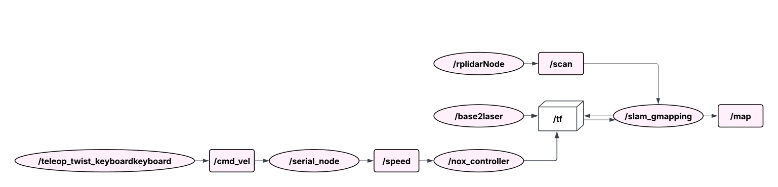
In Fig. 1, the data flows have the correct direction as required, and the publish and subscribe nodes are correct with the system. Node /rplidar processes data from lidar and publishes to topic/scan, the control signals from the keyboard are sent to topic/cmd_vel, the microprocessor will control the vehicle movement, and return the odometry values from the encoder to calculate the position of the robot published to topic/tf, Gmapping will register the topics needed for map construction as /scan and /tf, the map after construction will be published to the /map topic.
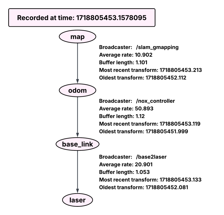
Run the command rosrun rqt_tf_tree rqt_tf_tree to get an image showing the connection between frames, tf, and nodes during data collection. Above is the tf_tree diagram, including the frames linked together. The map frame is the global frame; this will be the fixed frame that other frames must rely on this frame to calculate their relative position. The Odom frame is a child frame of the map frame; this conversion is created by the slam_gmapping node. Similarly, for the remaining frames, the conversion between frames and the update frequency between them will be adjusted to suit the system's response. All frames referenced in a system must be linked together and linked to the global frame (map frame). Each frame in the diagram can only have a maximum of one parent frame and can have many child frames. The tree diagram in Fig. 2 showing the connection between frames is very important, directly affecting the location and operation of the system.
The ROS Navigation Stack enables robots to map environments, localize themselves, and plan safe paths.
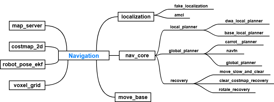
Fig. 3 depicts the communication diagram between nodes in the ROS Navigation Stack package, showing the structure and relationship between the main components. In which the central node move_base plays a coordinating role, connecting modules such as map_server, costmap_2d, robot_pose_ekf, and voxel_grid to build the map and determine the robot state. The nav_core component contains extended interfaces such as local_planner, global_planner, and recovery, which are responsible for path planning, obstacle avoidance, and error recovery. In addition, the localization branch, including amcl and fake_localization, ensures that the robot accurately determines its position on the map, helping the entire system work smoothly in coordination during navigation. Building on this foundation, the following sections present navigation algorithms and localization algorithms in greater detail.
The Dijkstra algorithm is a classical graph search method used to determine the shortest path between two points based on the minimum cumulative cost. In robot navigation, the cost typically includes both the path length and the risk of collision with obstacles. A shorter and safer path allows the robot to reach the target efficiently while minimizing the chance of encountering obstacles.
Compared with A* algorithm, Dijkstra’s method does not rely on any heuristic function to estimate the distance to the goal. This characteristic ensures that Dijkstra always finds the optimal (shortest) path if all edge weights are non-negative [17]. In contrast, A* integrates a heuristic term to guide the search toward the goal more efficiently, which generally reduces computational time but may yield suboptimal paths if the heuristic is not admissible or poorly defined [18]. Therefore, Dijkstra is selected in this study because it guarantees the globally optimal solution, which is desirable for ensuring safety and precision in robot path planning.
Although Dijkstra is computationally more expensive and slower than A*, this limitation can be mitigated with modern hardware or efficient graph representation techniques. Considering the objective of this research–achieving the most optimal and collision-free path–Dijkstra provides a reliable solution for global path planning. Comparison is shown in Fig 4.
Algorithm comparison A* | Algorithm comparison Dijkstra |
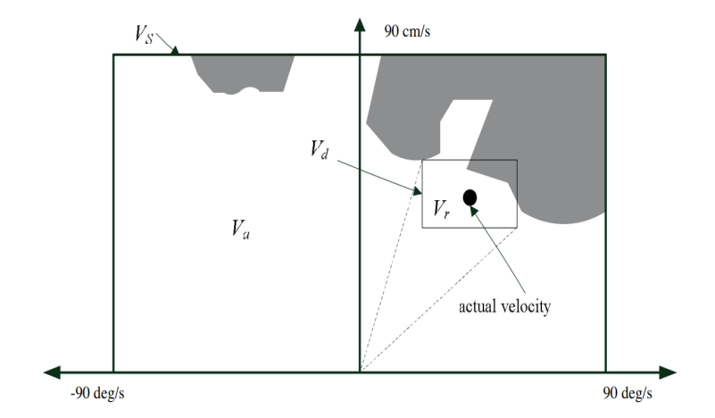
Step 1: Determine the possible trajectories based on the limits of linear velocity. The DWA algorithm generates circular trajectories (curved paths), each uniquely defined by a pair of linear velocity and angular velocity in (1).
| (1) |
Step 2: Predict feasible velocity values for the trajectories. To generate a safe path for the robot to avoid obstacles, a pair of velocities ( ) is determined such that the robot can stop before the nearest obstacle without collision along the corresponding curved trajectory. The formula is shown in (2).
| (2) |
Step 3: Dynamic Window. This step constrains the set of admissible velocities to those that can be achieved within a given time interval under the robot’s maximum acceleration. Let t denote the time during which the accelerations ( ,
,  ) are applied, resulting in the actual velocities () that will be commanded to the robot. From this, the feasible velocity set is defined in (3).
| (3) |
By combining the three constraints above, the motion space can be obtained by computing their intersection, as shown in formula (4).
| (4) |
In Fig. 5, for optimization, the trajectory with the highest score will be selected as the control trajectory for the robot in the next step.
The optimization formula is shown in (5):
| (5) |
In there:  : is the value that measures the degree of adherence to the planned trajectory.
The value of  ) calculated by the formula
  , with
  is the angle between the robot's direction and the destination point.
Function  represents the distance from the robot to the nearest obstacle on its curved trajectory. The smaller this value is, the higher the probability that the robot will move close to the obstacle, and then it will move around the obstacle.
Velocity: the function  is the straight moving speed of the robot and supports faster movement. The coefficients
  ,
,  , and
, and  are determined based on the specific objectives of this study, which focuses on local trajectory planning for obstacle avoidance (both static and dynamic) using the Dynamic Window Approach (DWA) algorithm for industrial autonomous mobile robots operating under the ROS platform.
These coefficients are experimentally tuned to balance three competing factors: path tracking accuracy, obstacle avoidance safety, and movement efficiency. Proper selection of these weights ensures that the generated trajectory is both safe and dynamically feasible within industrial environments.
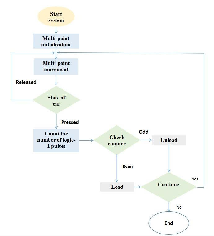
The operation process of the robot can be explained more clearly using a flowchart, as illustrated in Fig. 6. This flowchart presents the main steps from system start-up, checking the robot’s state, performing pick-and-place actions, and continuing the task if there are new waypoints.
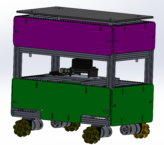
Overview diagram of the operation process of the autonomous mobile robot system. After choosing the suitable hardware components, the robot was designed in SolidWorks in Fig. 7 to make the installation clearer. The robot has three main layers. The first layer contains the microcontroller and the embedded computer. This arrangement helps with wiring and keeps the robot’s size compact. The second layer is for the LiDAR sensor, which needs a wide view to scan the environment. This makes the mapping more complete and the navigation more accurate. The third layer holds the lifting mechanism, which includes one electric cylinder and four lead screws to move the platform in a stable and precise way. The outer frame is designed to protect the electronics inside, but is also easy to remove for maintenance and repair.
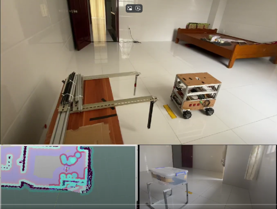
To test the operation of the robot, the team carried out an experiment to check its multi-point movement ability in a small space with fixed obstacles. The robot was able to reach all three target points. However, hardware errors and the slippery floor made it harder to follow the planned path. With real-time localization, the robot could return to the path quickly. Because high accuracy was needed at the target points, the robot took more time to finish the task. Experiment on multi-point movement with fixed obstacles.
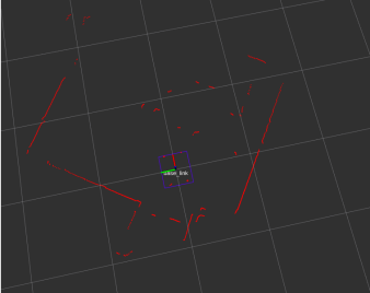
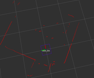
Use the Laser Filter package to filter out unwanted obstacles that appear in the data. After passing through the Laser Filter, the four obstacle points in the chassis no longer appear, but do not lose the details of the surrounding environment. The Laser Filter has worked according to the system's requirements. Lidar data before and after the laser filter are shown in Fig. 8.
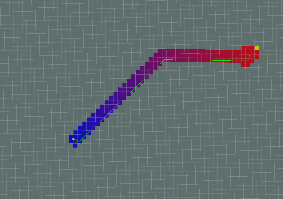
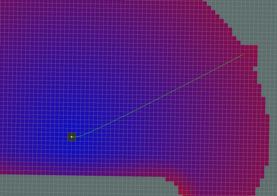
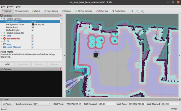
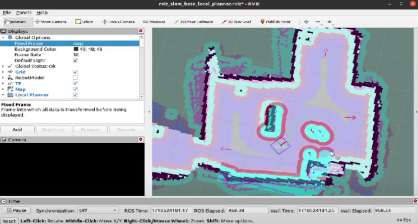
When the robot is running, from the raw binary map after the Gmapping process, Navigation will add virtual layers on the map to optimize the path planning for the AMR vehicle, helping to optimize movement and avoid obstacles. Instead of just processing everything on an embedded computer, the team designed a Raspberry Pi 4 as a ROS Master and a fixed computer for heavy processing (Gmapping, Navigation). With its quad-core ARM Cortex-A72 processor (1.5 GHz) and up to 8 GB of RAM, the Raspberry Pi 4B can efficiently execute critical ROS packages such as Gmapping, Navigation Stack, and OpenCV-based image processing, enabling both real-time perception and control [19]. The embedded computer installed on the vehicle is responsible for processing signals from the LiDAR sensor connected directly via the USB port and serial communication with the microcontroller to control the motors, processing encoder signals returned to the microcontroller. In parallel, a remote fixed computer is placed in a fixed position, acting as a device for observing, commanding, and performing processing tasks that require a lot of hardware resources, such as Gmapping, Navigation, instead of the Raspberry Pi embedded computer. Using the SSH protocol to communicate between the fixed computer and the Raspberry Pi 4, when operating, configure a static IP address for the Raspberry Pi and the fixed computer so that both can connect to the same WiFi address. Additionally, Raspberry Pi 4B supports flexible connectivity (Wi-Fi, Ethernet, Bluetooth) to communicate with ROS Master, sensors or other nodes without additional hardware. The system is controlled through the RViz interface provided by the ROS system in Fig. 9.
The robot was able to reach all three target points. However, hardware errors and the slippery floor made it harder to follow the planned path. With real-time localization, the robot could return to the path quickly. Because high accuracy was needed at the target points, the robot took more time to finish the task.
To test the operation of the robot in a more complex environment with moving obstacles, the team carried out an experiment to check its multi-point movement ability in a small space with moving obstacles. Multi-point movement experiment with moving obstacles in Fig. 10.
The results showed that the robot could avoid moving obstacles. When a moving obstacle appeared, the DWA algorithm quickly created a new path to avoid it in an optimal way. However, in some cases, when the obstacle was too close to the robot while moving, the hardware limits and the algorithm made it too slow to react. In this situation, the DWA algorithm could not find another path, so the robot stopped and waited until the obstacle was gone before continuing to move.
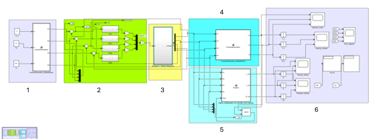
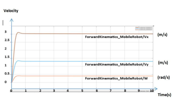
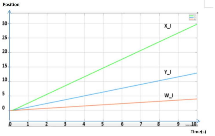
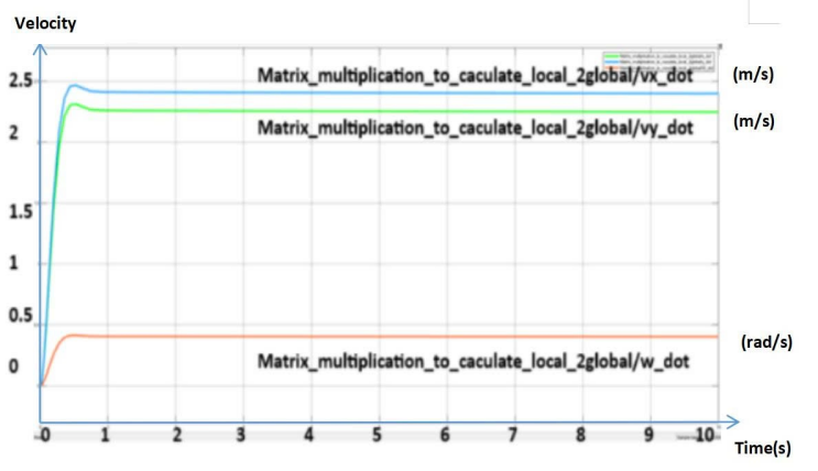
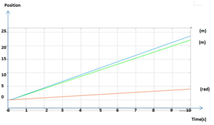
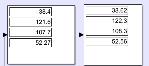
Kinematic verification using MATLAB in Fig. 11. In this part, the group uses MATLAB/Simulink to simulate and verify the kinematics of the AMR vehicle using a PID controller. Block 1 is the input block, entering the vehicle velocity value that will be calculated through the 4 rotation angles of the 4 wheels. Block 2 is the PID controller, processing the error and transmitting the signal to the next block. Block 3 is the dynamics block. Block 4 is the local system kinematic block, calculating the 4 rotation angles of the wheels into the vehicle velocity. Block 5 is the global system kinematic block, calculating the 4 rotation angles of the wheels into the velocity of the global system. Block 6 is the observation block, showing the output results of the position and velocity of the global and local systems. The group provides the set value for the vehicle velocity, uses PID to process the error, and then the result.
The chosen motion parameters –  m/s,
m/s,  m/s and
  rad/s – were determined based on dynamic feasibility, safety considerations, and agreement with previous studies on autonomous mobile robots (AMR). These values represent a balance between performance and stability, ensuring the robot operates efficiently without exceeding kinematic and dynamic limits. Exceeding these limits can lead to wheel slippage, actuator saturation, or loss of control. Velocity regulation plays a critical role in ensuring smooth, collision-free motion and maintaining system stability. Recent studies also emphasize that the choice of velocity directly affects the performance of cost mapping and dynamic obstacle avoidance in ROS-based AMR, stating that the robot velocity is an essential input for dynamic obstacle avoidance and for determining the feasibility of motion in the local cost map [20].
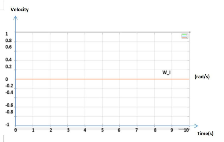
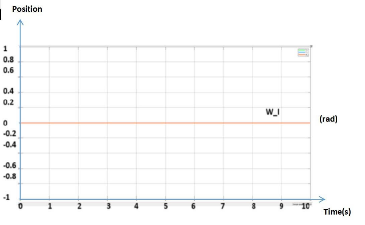
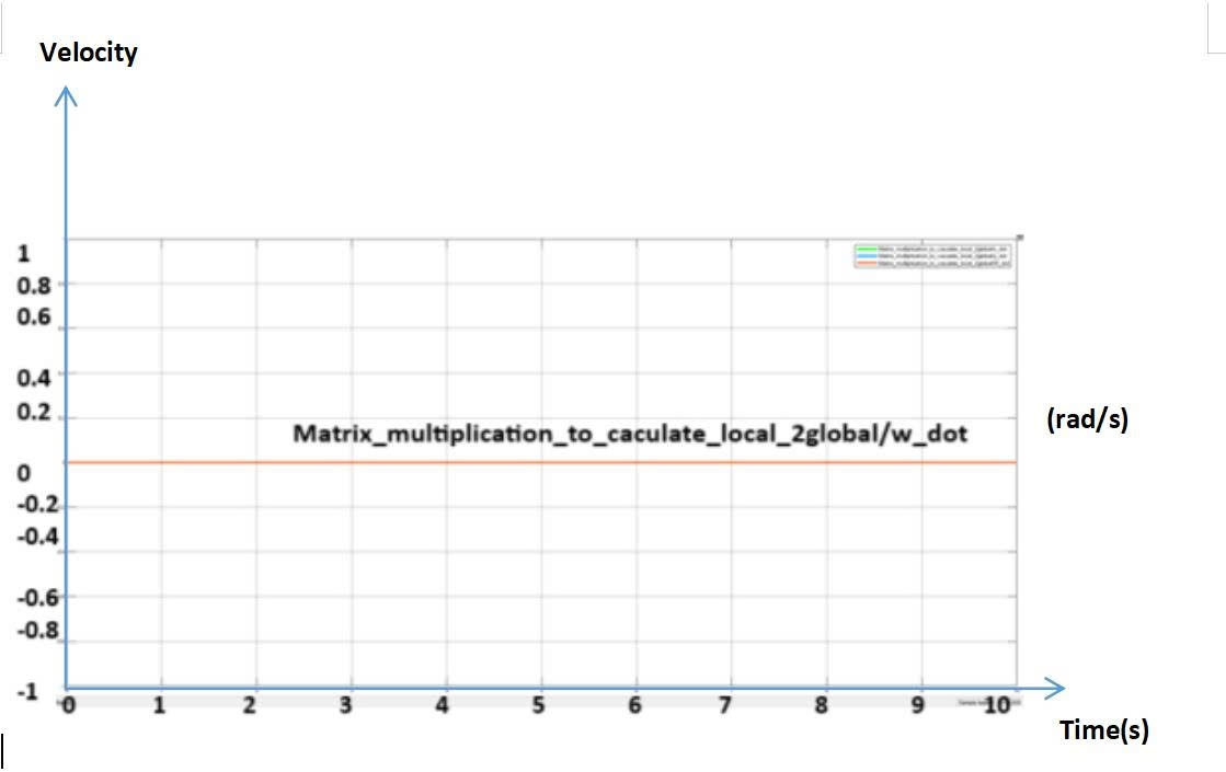
In our study, after establishing theoretical limits for these velocity values, we performed simulation-based verification and experimental refinement in MATLAB to confirm that the selected parameters produced stable trajectories and responsive navigation under real-world conditions. This iterative refinement ensured that the selected linear and angular velocities remained consistent with AMR standards, where most platforms operate at linear speeds of 1–3 m/s and angular velocities below about 0.5 rad/s. The
experimental results are presented in the graphs below from Fig. 12 to Fig. 15.
Thus, through the experimental results in Fig. 16, it can be concluded that the PID controller parameters found by trial and error method have a good response, suitable for robot control. The calculation formula for forward, backward, and kinematics has been calculated accurately. The output response of vehicle velocity is set in the first 1 second and stable throughout the simulation process. The error of the set rotation angle and the achieved rotation angle is small, meeting the error standard of 2–5%.
When the control signal is off, both the speed and position signals are 0, the vehicle is stationary, very close to reality. The experimental results are shown in Fig. 17 to Fig. 20. Evaluate the use of the PID controller suitable for the actual construction system.
After the multi-point movement tests in a small space, the next experiment focused on the robot operating in a randomly arranged workspace. In this movement experiment, the team designed two pick-and-place points located in two different rooms, separated by a narrow hallway with many details. A survey of the robot’s operation ability in a general environment is shown in Fig. 21.
The results showed that the robot completed three consecutive pick-and-place actions. However, because of the complex environment and hardware errors, the movement was not always smooth. The robot sometimes stopped, especially near doorways, and needed more time to reach the exact position and orientation for pick-and-place. Since the lifting depends fully on the robot’s final position, errors in accuracy could cause the action to fail.
From the continuous experiments in different movement cases and working environments, the robot’s operation was found to be fairly accurate and stable. However, because of errors and the limited response of hardware and software, the moving speed is still slow in order to keep accuracy. At present, the robot needs about 60 seconds to move between two points 5 meters apart, and up to 250 seconds for longer paths with the lifting system included.
From current research, the AMR autonomous vehicle system has gradually affirmed its importance and convenience in operating production systems in all areas of life, especially in the industrial sector, contributing to optimizing labor costs and promptly meeting the needs of businesses for customers.
In this research, the team has optimized the system with a split distributed architecture based on ROS, separating control and computing tasks between Raspberry Pi 4B (playing the role of ROS Master) and a remote computer that handles heavy tasks such as Gmapping, Navigation to help improve accuracy in positioning and navigation, while maintaining high response speed by reducing the computation load on embedded hardware. This approach brings high flexibility in operation, allowing for easy expansion or maintenance of the system without changing the hardware structure. Combined with the research results, we also found that the vehicle model operates relatively stably, meets the requirements of flexible transportation and handling, compact design, stable lifting mechanism, and the entire system is automated for moving, picking up, and returning goods. The research has made a significant contribution by demonstrating that a cost-effective distributed ROS architecture can provide stable real-time control, effectively reduce the computational load, and integrate mechanical lifting mechanisms in a unified framework. This is in contrast to many previous studies that focused on single-board solutions without external computing nodes or ignored the integration of dedicated mechanical subsystems [12]. Typically, AMR research relies on a single embedded computer, such as a Jetson Nano or Raspberry Pi, that handles all tasks from SLAM to motor control [21].
However, the hardware design is not stable, leading to wheel slippage, slow vehicle speed due to the use of small wheels, and imperfect traction. These mechanical issues reduce the accuracy of motion, an issue also observed in previous AMR prototypes using low-torque motors [16]. In addition, since the communication between nodes is based on Wi-Fi, the data transmission rate directly affects the system's responsiveness. Similar concerns have been discussed in studies on distributed ROS, where network latency and non-deterministic communication can affect real-time behavior [22]. Therefore, based on the practical requirement of improving the quality of control with high accuracy, the response time, as well as the mechanical properties of the model, still need to be further researched and developed in the future.
Nevertheless, the team's practical results show that the model still operates relatively stably and accurately, demonstrating the potential of ROS-based structural analysis in optimizing performance and hardware costs for system AMR enhancement.
Through the research and implementation of the project, the proposed system has achieved its main objectives. This study has demonstrated a ROS-based distributed architecture for AMR that can effectively separate embedded control from high-level computation, improving efficiency and scalability for industrial applications. Our research has been able to contribute to bridging the research gap, where many current AMR studies still rely on monolithic embedded architectures and lack mechanical integration for autonomous lifting. By combining a distributed ROS system, a robust LiDAR-SLAM pipeline, and a ROS-controlled lifting mechanism, the proposed model demonstrates a practical and modular platform for future AMR implementations. However, the system still has some limitations as mentioned above.
In the future, the system can be further improved by upgrading both hardware and software, as well as applying image processing techniques to enhance the cargo handling process. In particular, the communication framework of Raspberry Pi 4B relies heavily on Wi-Fi connection, making the system susceptible to latency and packet loss. As the industrial environment increasingly adopts private 5G and deterministic Ethernet, our future research will focus on integrating real-time network solutions that ensure predictable latency and higher throughput, which can fully realize the high-performance AMR fleet system.
We want to give thanks to PhD. Vi-Do Tran (HCMUTE) due to his supervion for us to complete this contribution. The video link of operation of our AMR is: https://www.youtube.com/watch?v=jInfEFWDjpc
Nam-Long Doan, A Study of Autonomous Mobile Robot