Journal of Fuzzy Systems and Control, Vol. 3, No 3, 2025 |
Study, Design, Modeling, Simulation, and Control Analysis of AC-AC Power Converters
Salam Waley Shneen 1,*
1 Energy and Renewable Energies Technology Center, University of Technology, Baghdad, Iraq
Email: 1 salam.w.shneen@uotechnology.edu.iq
*Corresponding Author
Abstract—The current study aims to provide an analysis of the performance of the AC power converter by constructing a simulation model. A preliminary simulation model is designed to identify the behavior of open-loop and closed-loop systems. To improve the converter's performance, pulse width modulation (PWM) technology and a conventional controller are used to control the converter's output voltage and frequency. An AC converter varies electrical quantities to suit the load requirements and the available power source. Converters can be used in lighting circuits to control the intensity of lighting and to control the rotational speed of electric motors, such as single-phase induction motors. The power electronics converter model is an AC voltage control unit type, built using electronic switches, which are semiconductor devices such as thyristors and transistors (IGBT, MOSFET). The input terminal of the converter is connected to a constant voltage and frequency AC power supply, while the output terminal is connected to an AC load, controlled by the root mean square value of the AC voltage. The output of the converter can be controlled by regulating the operating periods of the electronic switches, depending on the type and method of connecting the switches, whether full wave or half wave, with regulated periods. The study presents a test of AC converter, and through simulation results, it is shown that the converter's performance can be improved using pulse width modulation technology and a conventional PID controller. Modeling a single-phase AC transformer system using a thyristor as an electronic switch. The system model consists of a 100V, 50Hz single-phase power supply connected in series with a transformer containing two thyristor switches connected in parallel. The transformer output is connected to a load with a resistance of 10 ohms. Tests were proposed using single-phase converter simulation models, where the switching angle of the electronic thyristor was changed from 10 to 90 degrees in 10-degree increments. The simulation results showed that the converter's output voltage could be changed by changing the switching angle, with the change being inverse; that is, increasing the switching angle leads to a decrease in the converter's output voltage.
Keywords—Power Electronic Converter; AC-AC Converter; Open Loop System; Closed Loop System; PID Controller
AC converters are classified into two types based on the number of phases, including single-phase and three-phase converters. Single-phase or three-phase AC converters are divided into two types based on the control unit and the number of switches, depending on whether they are half-wave or full-wave. AC converters are also given two names, including unidirectional or bidirectional, and can therefore be expressed in one of the following terms. First, Half-wave single-phase AC voltage controllers (unidirectional controllers). Second, Full-wave single-phase AC voltage controllers (bidirectional controllers). Third, half-wave three-phase AC voltage controllers (unidirectional controllers). Fourth, Full-wave three-phase AC voltage controllers (bidirectional controllers) [1]-[3].
Power electronics devices are used to convert energy. One of them converts a constant alternating current (AC) from the power supply (voltage and frequency) into an alternating current (AC) with variable voltage and frequency depending on the load requirements. AC converters modify the frequency and are called AC voltage controllers. Another type is AC regulators. This type changes the mean square (RMS) voltage to meet the load requirements at a fixed frequency. Common methods for converters include on/off control of electronic switches, phase angle control, or pulse width modulation (PWM) AC voltage control. Converters can be used in many fields and applications, including industrial, agricultural, and domestic applications, controlling the rotational speed of motors in electric fans and pumps, and controlling room temperatures in heating devices, among others [4]-[6]. Single-phase AC voltage control unit, the simulation model can be represented using an SCR thyristor with three terminals: anode, cathode, and gate. The anode of the first thyristor is connected to the source and is considered the first terminal of the electronic switch, while the second terminal of the thyristor (cathode) is connected to the load terminal of the source. The electronic switch represented by the thyristor works by triggering its gate, which is the third terminal, and is associated with an on-off control technique. The switching occurs when there is a trigger pulse for the gate. A model can be built consisting of two SCR thyristors connected in parallel, the anode of the first with the cathode of the second and the cathode of the first with the anode of the second [7]-[9].
Currently, various types of electronic power converters are used in many fields and industrial applications, one of the most important of which is industrial power converters. They are an essential part of electrical power systems in generating stations, distribution systems, and transmission systems, through their connection to the main grid and sub-grids. Electronic power converters are used in energy generation systems from sustainable development sources, and clean energy is a good example of this. The functions of electronic power converters vary according to the need for them, including changing the type of voltage, current, and frequency, which are electrical quantities. Electronic power converters can be classified into buck, step-down, boost, and step-up [10]-[12].
Energy exists in nature in various forms and can be converted from one form to another depending on availability and need. Electricity can be generated from various sources. Currently, the focus is on renewable energy sources. Electricity is widely used to power most machines, factories, buildings, and other various life facilities. Researchers are currently interested in studying renewable energy systems due to the progress achieved in the field of generating electrical energy from environmentally friendly sources. Renewable energy sources are characterized by their high efficiency and relatively affordable energy production costs compared to conventional sources, in addition to addressing the problem of environmental pollution. Researchers present a simulation model using engineering computer programs to identify system behavior according to proposed tests that simulate real-time operation. The specifications of the proposed system are assumed based on data suitable for locations with the same proposed specifications. A prototype is presented and operated, and based on the results, the model is improved to arrive at an appropriate design that meets the load requirements [13]-[15].
The first component is the power supply, which provides the system with electrical energy. This is the energy source that powers the system, such as generators, solar power, wind power, etc. The second component is a power converter from one quantity to another, such as a lower power converter or a higher power boost converter, or from DC to AC (inverter) or an AC-to-AC converter (AC voltage controller). Another component may be a storage unit, such as a battery. A simulation model can be built using engineering software to represent and operate the system, understand its behavior, and verify its effectiveness. When relying solely on a single source, such as solar energy, it can be affected by changing climatic conditions, such as seasonal variations and day and night hours, requiring an energy storage unit to compensate for energy shortages and store excess energy [16]-[18].
This work aims to demonstrate how to build a model of a single-phase AC converter. The converter's behavior is understood by constructing a suitable model based on the application and function; some models require single-phase operation, while others require three-phase operation. The system model consists of an AC power supply and electronic switches such as a transistor switch, thyristor, IGBT transistor, or diode, as well as various types of loads such as resistors, motors, and lamps. Additional components, including a controller and pulse-width modulation (PWM) technology, are required to provide the appropriate output.
To understand the system behavior of the proposed models that achieve the objectives of this study, the following contributions can be made. The first contribution involves the construction and design of an open-loop control simulation model of an AC-AC power electronic converter. This includes the implementation and operation of a set of circuits, using the principle of changing the firing angle value from angle (alpha). The second contribution involves the construction and design of a -loop control simulation model of a single-phase AC-AC converter. This also includes the implementation and operation of a set of circuits, using the principle of changing the firing angle value from angle (alpha). Electronic devices convert a constant source voltage to a variable voltage that meets specific requirements. Some studies focus on AC converters, including single-phase AC-to-AC converters. This research aims to understand how to construct and mathematically model this type of converter, calculate the system components, and develop a prototype. Simulation allows for determining the system's dynamic behavior. Analysis of the results of proposed tests can then be used to add a controller to improve system performance. The study presents a mechanism for identifying AC-AC power converters, a type of electronic power converter. It contributes to implementing and establishing appropriate design steps, in addition to constructing a simulation model to identify system behavior over a specific operational period. This study of single-phase AC converters includes a mathematical model based on the theories and laws relating to the system components. Different types can be distinguished by their classification into half-wave single-phase AC converters and full-wave single-phase AC converters.
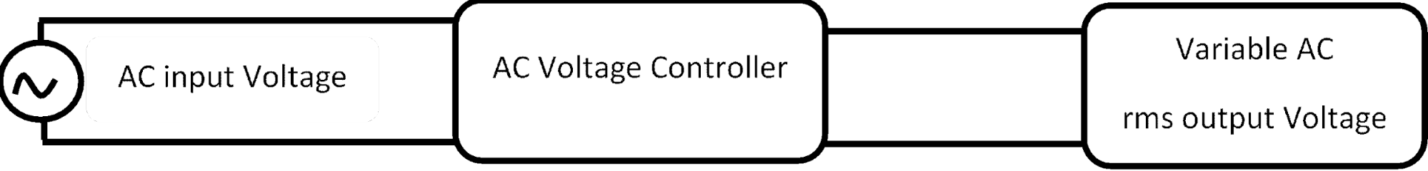
There are two types of AC converters: single-phase and three-phase. The first research contribution examines the on-off control technique for single-phase converters. The second contribution examines the phase angle control technique. The third contribution examines a half-wave three-phase converter, and the fourth contribution examines a full-wave three-phase converter. Applications of converters include the tap ginger converter and the track light dynamic control circuit. AC voltage controllers are used to control the RMS value of the AC voltage applied to the load circuit at the same frequency. AC voltage control of a type of thyristor power electronic converter is used to convert a voltage to a frequency. AC is supplied to a flexible AC output voltage with a voltage-to-frequency, as shown in Fig. 1 [19]-[21].
There are two types of thyristor control techniques and phase angle control techniques that include, first, the thyristors are used as switches to connect to the load circuit to the input AC supply for a few cycles of the input AC supply, and then to disconnect it for a few input cycles. Second, the thyristors are used as switches connecting the load circuit to the input AC supply Source, for a part of each input half cycle, and then are turned off during the remaining part, by controlling the phase (triggering) single. The applications of voltage controllers include light dimmer circuits, induction heating, industrial, household heating, on-load transformer tap changing, and speed control of single-phase and three-phase induction motor [22]-[24].
In the on-off control technique, the thyristor switches (S1 and S2) are turned on by applying appropriate gate trigger pulses to connect the input AC supply to the load for a number of input cycles (n) during the time interval (ton). The thyristor switches (S1 and S2) are turned off by blocking the gate trigger pulses for a number of input cycles (m) during the time interval (toff). Thyristors are turned on at the voltage zero crossing of the input supply. The S1 turned on for each positive half cycle with a gate trigger pulse (ton). The S2 turned on for each negative half cycle with a gate trigger pulse (toff) [25]-[27].
| (1) |
| (2) |
| (3) |
| (4) |
| (5) |
| (6) |
Electrical and electronic systems are fundamental to numerous applications across various fields, particularly industry. Their use in industry is widespread globally. These systems are built from diverse energy sources, including renewable and non-renewable energy. Distribution and transmission systems are key components, along with inverters, loads, and control systems. Researchers highlight one of the most important components of electrical and electronic systems: the inverter. The inverter is essential for converting the available electrical current from the power source, connected to the inverter's input, into a different quantity according to the requirements of the load connected to the inverter's output. There are four main types of inverters, classified according to their input and output currents. The first type converts alternating current (AC) to alternating current (AC), the second converts AC to direct current (DC) (voltage rectifier), the third converts direct current to direct current (DC), and the fourth converts DC to alternating current (source voltage inverter) [28]-[30].
A great deal of research is currently underway in this field. Researchers in the first research area focus on understanding AC-to-AC converters by studying single-phase and three-phase AC-to-AC converters. Others in the second research area address how to design these converters. The third research area focuses on how to model them. The fourth research area focuses on how to control them, while the fifth research area analyzes their dynamic behavior [31]-[33].
To provide a comprehensive and in-depth study, it is necessary to review previous literature, within the scope of this study, on AC-to-AC converters. This research will address the fundamental concepts related to these converters, their types, the components of each type, their characteristics, and their appropriate applications based on their functions and system requirements. Classifying converters as single-phase or three-phase, depending on the power source, is a fundamental and important concept. Similarly, the concept of half-wave or full-wave operation for single-phase or three-phase converters depends on the number of electronic switches. Electronic switches are a type of semiconductor used for frequent switching and switching at a specific frequency. On/off periods can be defined using modern techniques such as pulse width modulation [34]-[38].
AC-to-AC converters can be designed to illustrate how the system components are used, in addition to the mathematical relationships that represent the system. Design calculations can be performed after determining the system characteristics that meet the functional requirements of an application similar to the model. The design requires selecting system parameters, including input and output parameters such as the input voltage and frequency from the power supply, and the required output voltage and frequency. These parameters allow for determining the type of converter: step-up or step-down, as each type has a suitable mathematical representation. Building and designing a suitable model requires determining the technology that controls the opening and closing of electronic switches, as well as regulating these intervals to suit the desired system output. The technology proposed in most previous and current studies involves a pulse generator that determines the operating period and repetition frequency, thus defining the operating cycle of the switch's operating pulse. Another approach is to use pulse width modulation (PWM), which can be used to control the switch opening and closing intervals. Closed-loop systems are essential for addressing source and load disturbances that affect switch operation, necessitating the addition of controllers to optimize performance [39]-[42].
The researcher proposes a simulation model for an open-loop and a closed-loop system of a single-phase AC-to-AC converter using two thyristors connected in parallel. Each thyristor transmits half of the input waveform, and the trigger angles are varied to suit different applications and to verify the possibility of obtaining different output values. The system consists of a 100 V AC supply at 50 Hz, feeding an AC load with a resistance of 10 ohms. The model is tested with trigger angles varying by 10 degrees, and then from a 10-degree trigger angle to a 90-degree trigger angle. The simulation results allow for a comparison between theoretical calculations and the simulation results, highlighting the differences between the closed-loop and open-loop systems.
The RMS output voltage can be calculated from the mathematical equation that relates the root-mean-squared output voltage, the maximum instantaneous value, the proposed trigger angle of the thyristor, and the complete cycle period, as shown in Table 1. The current value can also be calculated using Ohm's law by dividing the voltage by the resistance value, which was suggested in the tests as 10 ohms. The values of the currents corresponding to the voltage are as in Table 2.
| (7) |
| (8) |
α |
|
10 | 68.7806 |
20 | 66.7187 |
30 | 64.5283 |
40 | 62.2878 |
50 | 60.0537 |
60 | 57.7821 |
70 | 55.3598 |
80 | 52.7245 |
90 | 49.9259 |
α |
|
10 | 6.8781 |
20 | 6.6719 |
30 | 6.4528 |
40 | 6.2288 |
50 | 6.0054 |
60 | 5.7782 |
70 | 5.5360 |
80 | 5.2725 |
90 | 4.9926 |
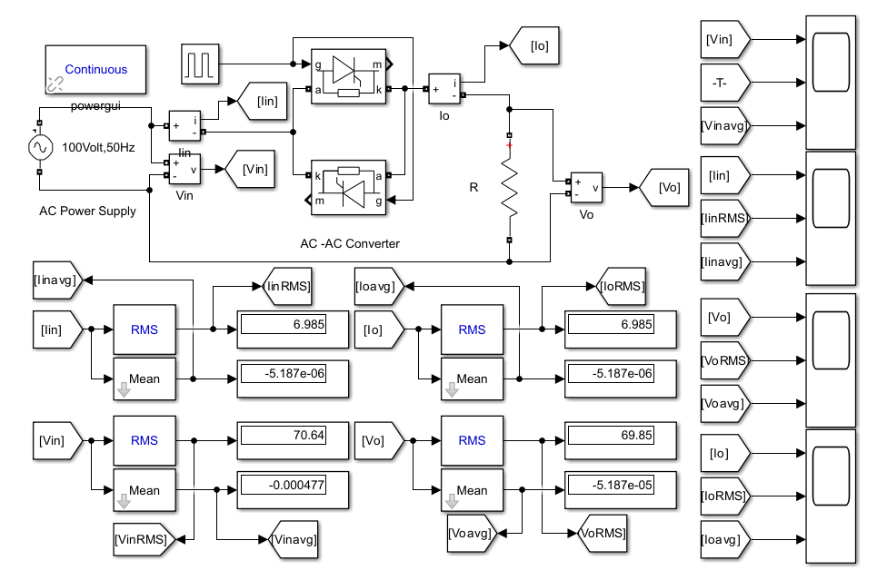
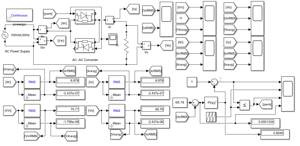
The first research contribution involved conducting a prototype test of an open-loop system consisting of a 100 V, 50 Hz AC power supply feeding a 10-ohm resistive load connected to the output of an AC-to-AC converter. The figure represents the system state during a 0.1-second operating time test. A voltage and current sensor and a voltage and current waveform oscilloscope can be observed at the system's input and output.
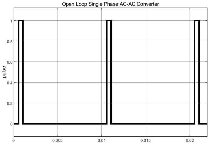
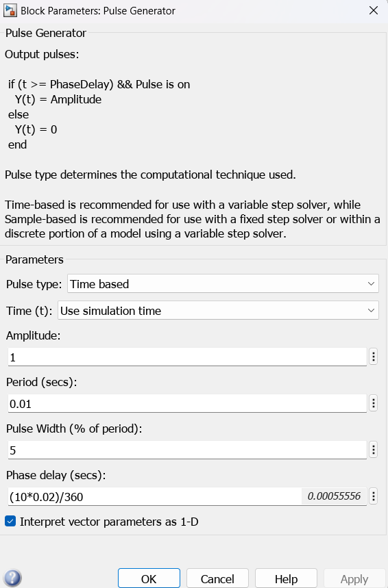
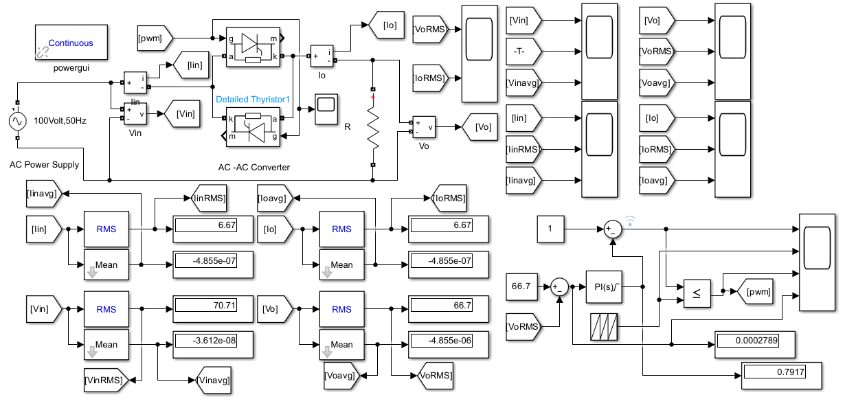
From the Fig. 2 we note that the voltage and current are recorded as (root-mean-square), 69.85 volts, and the current as 6.985 when the input voltage is 70.64, and the current is equal to the output current. By changing the trigger angle, the output of the converter can be controlled, and how it changes can be seen as shown in the pulse generator parameter and waveforms of the trigger pulse in the Fig. 3 and Fig. 4.
Fig. 2 represents an open-loop system model. The figure shows the system components and allows for testing to determine the system's behavior and to verify the possibility of obtaining a variable voltage from a constant voltage. For example, changing the value of the trigger angle from angle (α) = 10, the results of which can be plotted in Fig. 5 to Fig. 8, and so on for a range of values, and recording the electrical quantities, including the voltage, output current, and input current, as shown in the figures and Table 3.
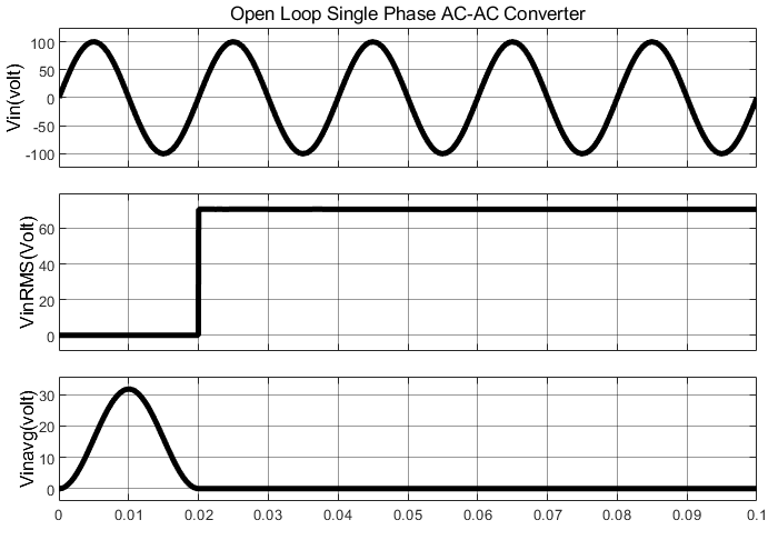
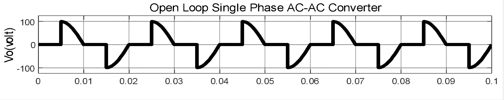
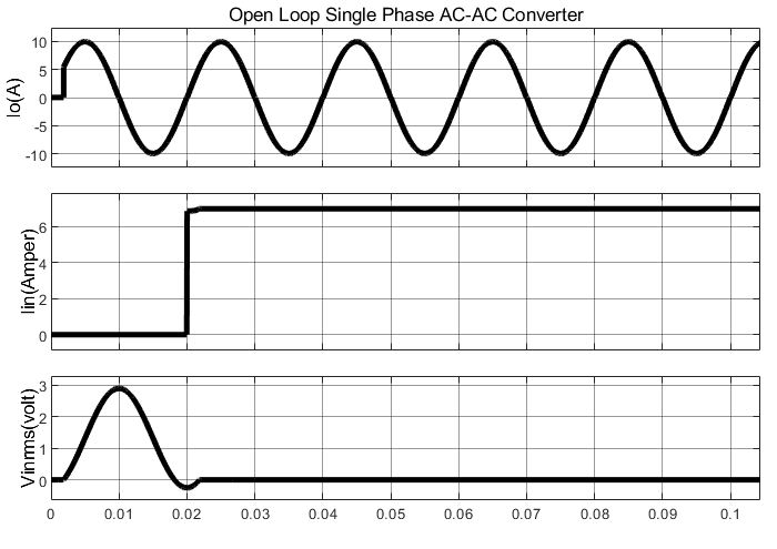
Fig. 5 represents the system’s response to voltage waves and signals. An alternating wave with an input voltage of 100 volts, as in the first signal, for an operating time of 0.1 seconds. By taking one cycle, the frequency of the wave can be determined by dividing the unit 0.02 to obtain the frequency of the wave. The shape and magnitude of the RMS voltage and the average of the input wave can also be identified, as in the second and third waves, in the same Fig. 5.
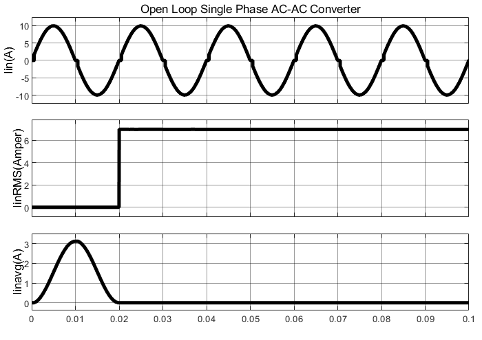
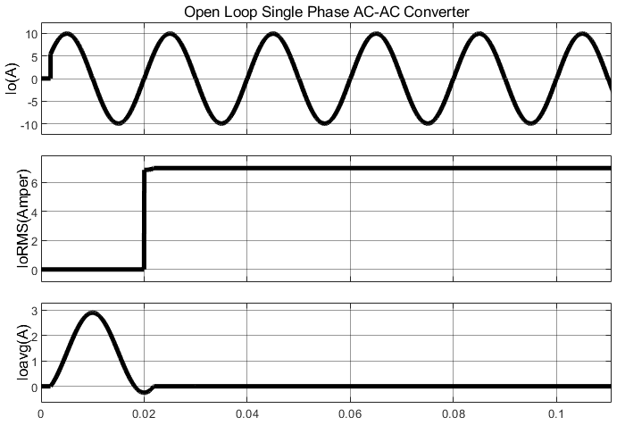
Fig. 6 represents the system's response to the current waves and signals. An alternating wave with an input current of 10 amps, as in the first signal, for an operating time of 0.1 seconds. By taking one cycle, the frequency of the wave can be determined by dividing the unit 0.02 to obtain the frequency of the wave. The shape and magnitude of the RMS and average current of the input wave can also be identified, as in the second and third waves, in the same Fig. 6.
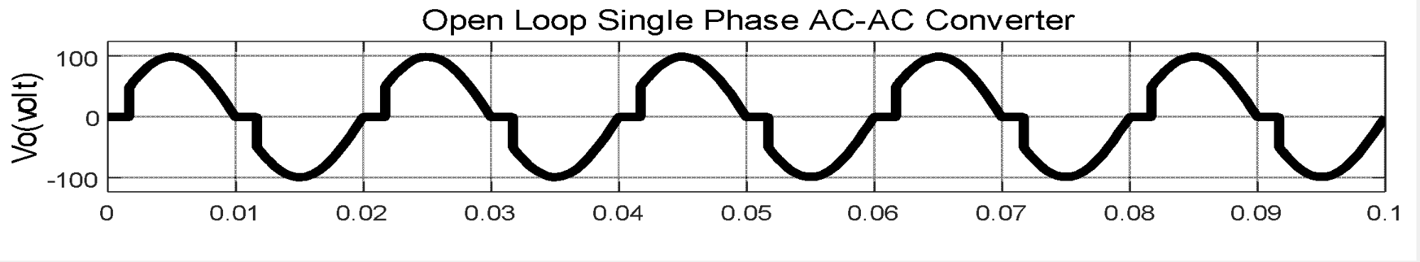
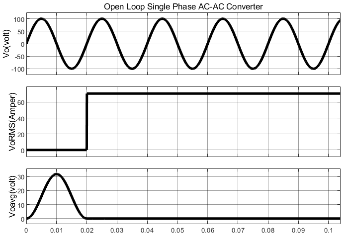
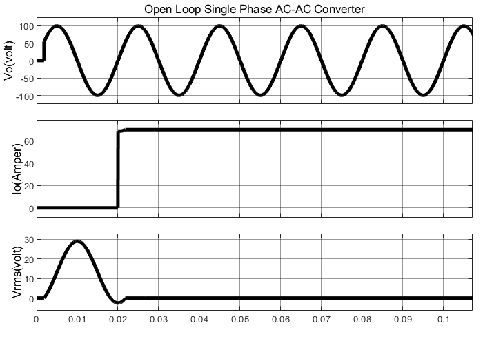
Fig. 7 represents the system’s response to voltage waves and signals. An alternating wave with an output voltage, as in the first signal, for an operating time of 0.1 seconds. By taking one cycle, the frequency of the wave can be determined by dividing the unit 0.02 to obtain the frequency of the wave. The shape and magnitude of the RMS voltage and the average of the input wave can also be identified, as in the second and third waves, in the same Fig. 7.
Table 3 represents an open-loop system, the countries include the electrical quantities of voltage and current, which represent the input and output of the system, with the angles of the spark changing from 10 to 90 by 10 degrees.
alpha | VinRMS | IinRMS | VoRMS | IoRMS |
10 | 70.64 V | 6.985 A | 69. 85 V | 6.985 A |
20 | 70.63 V | 6.935 A | 69.35 V | 6.935 A |
30 | 70.67 V | 6.815 A | 68.15 V | 6.815 A |
40 | 70.67 V | 6.6 A | 66 V | 6.6 A |
50 | 70.66 V | 6.282 A | 62.82 V | 6.282 A |
60 | 70.67 V | 5.866 A | 58.66 V | 5.866 A |
70 | 70.71 V | 4.778 A | 47.78 V | 4.778 A |
80 | 70.73 V | 4.14 A | 41.4 V | 4.14 A |
90 | 70.73 V | 4.778 A | 47.78 V | 4.778 A |
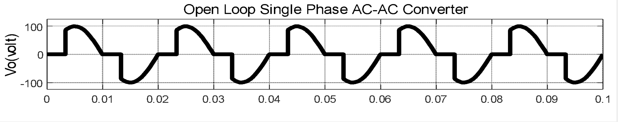
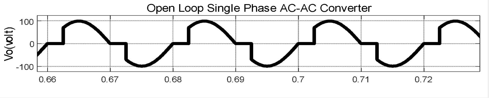
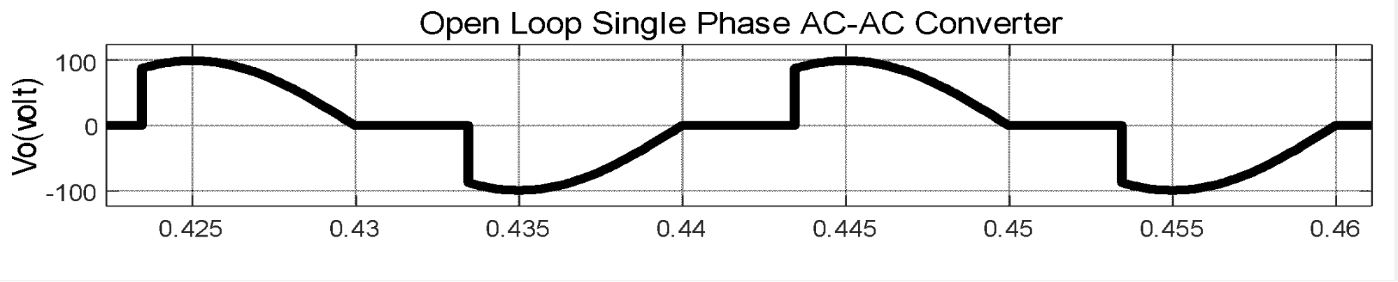
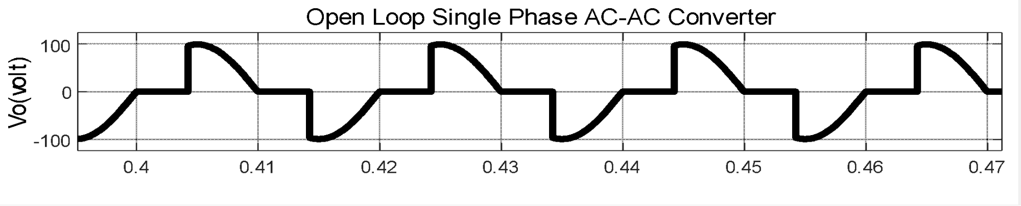
Fig. 8 represents the system's response of open loop control for AC power electronic converter at angle(alpha)=30. Fig. 9 represents the system's response of open loop control for AC power electronic converter at angle(alpha)=60. Fig. 10 represents the system's response of open loop control for AC power electronic converter at angle(alpha)=90.
The second contribution is by adding a conventional control unit within the closed-loop system by taking a specific reference value for load feeding, and its value can be changed according to the requirements for load coverage.
The feasibility of obtaining a reference value that matches the theoretical calculations can be observed, as shown in the Fig. 11 and Fig. 12. Furthermore, a comparison with the other system is possible, and the differences between them can be identified, as shown in Table 1 and Table 2. Fig. 13 to Fig. 17 representing the results for both the open-loop and closed-loop systems.
The waveforms can be observed as shown in the following figures, as well as the angle variations that trigger the thyristors, which in turn change the electrical output of the converter to meet the load requirements. The results for all proposed scenarios can be summarized in the Table 4.
Table 4 represents a closed-loop system, the countries include the electrical quantities of voltage and current, which represent the input and output of the system, with the angles of the spark changing from 10 to 90 by 10 degrees.
alpha | VinRMS | IinRMS(A) | VoRMS(V) | IoRMS(A) |
10 | 70.71V |
|
|
|
20 | 70.71V |
|
|
|
30 | 70.71V |
|
|
|
40 | 70.71V |
|
|
|
50 | 70.71V |
|
|
|
60 | 70.71V |
|
|
|
70 | 70.71V |
|
|
|
80 | 70.71V |
|
|
|
90 | 70.71V |
|
|
|
The thyristor was operated at angles ranging from 10 to 90 degrees at a rate of 10 increments. The simulation results showed the possibility of changing the transformer output voltage by changing the firing angle, as the change was inverse, i.e. when the firing angle increased, the value of the transformer output voltage was in a state of decreased, as in the figures and table mentioned in the previous paragraph.
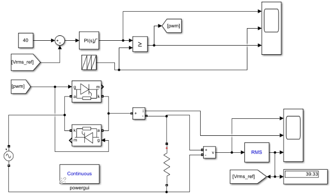
Currently, another closed-loop system test model has been proposed, which is a system in which feedback has been added by placing a transformer output voltage sensor to determine a suitable and required reference value as the transformer output. It has also been proposed to add a comparison between the reference value and the actual value of the transformer output, and a traditional PID control unit has been added to enhance the transformer operation, reduce the potential error, and improve performance, through which the transformer efficiency is increased, Fig. 18. Four reference values have been set to verify the effectiveness of the system and the possibility of obtaining the required values in the transformer output, including (30, 40, 50, and 70) volts. The simulation was conducted using the proposed model for the above test cases to verify the possibility of obtaining them in the transformer output. The simulation results showed the effectiveness of the system by being able to obtain the required values for the transformer output voltage, as shown in the Fig. 19 to Fig. 20.
Fig. 18 represents the system's response of closed loop control for AC power electronic converter at angle(alpha)=30. Fig. 19 represents the system's response of open loop control for AC power electronic converter at angle(alpha)=60. Fig. 20 represents the system's response of open loop control for AC power electronic converter at angle(alpha)=90.
A set of conclusions was reached through the proposed research contributions, which include verifying the effectiveness of the system using the closed-loop and open-loop models. A constant voltage AC converter can be built and designed at the input side of the converter, while a variable voltage can be obtained at the output by adopting pulse width modulation to change the electronic switching angle. A control unit can be built and designed to improve performance and give the required and specified voltage as a reference value in the closed-loop system. Future tests can be conducted to verify the use of other control units with linear and nonlinear systems, such as expert and intelligent.
Salam Waley Shneen, Study, Design, Modeling, Simulation, and Control Analysis of AC-AC Power Converters