Journal of Fuzzy Systems and Control, Vol. 3, No 3, 2025 |
Design and Implementation of an IoT-Enabled Autonomous Fire-Fighting Robot Using
Vision-Based Fire Detection
Hoang-Thong Nguyen 1, *, Quoc-Thuan Nguyen 2, Phuoc-Dat Tran 3, Quang-Khai Nguyen 4, Thi-Hong-Lam Le 5,
Le-Minh-Kha Nguyen 6, Van-Hiep Nguyen 7, Thanh-Binh Nguyen 8, Ngoc-Hung Nguyen 9, Thi-Ngoc-Thao Nguyen 10,
Son-Thanh Phung 11, Hoang-Lam Le 12, Thanh-Toan Nguyen 13, Hai-Thanh Nguyen 14
1, 2, 3, 4, 5, 6, 7, 8, 9, 10, 11, 12, 13 Ho Chi Minh City University of Technology and Engineering (HCM-UTE),
Ho Chi Minh City (HCMC), Vietnam
14 Nguyen Huu Canh Technical and Economics Intermediate School, Ho Chi Minh City (HCMC), Vietnam
Email: 1 21151354@student.hcmute.edu.vn, 2 21151356@student.hcmute.edu.vn, 3 22142104@student.hcmute.edu.vn,
4 21151419@student.hcmute.edu.vn, 5 lamlth@hcmute.edu.vn, 6 21145157@student.hcmute.edu.vn,
7 hiepnv@hcmute.edu.vn, 8 binhnt@hcmute.edu.vn, 9 hungnn@hcmute.edu.vn, 10 thaontn@hcmute.edu.vn,
11 thanhps@hcmute.edu.vn, 12 lamlh@hcmute.edu.vn, 13 22145267@student.hcmute.edu.vn, 14 nguyenhaithanh@nhct.edu.vn
*Corresponding Author
Abstract—This paper presents the design and implementation of an IoT-enabled autonomous fire-fighting mobile robot for early hazard detection, remote monitoring, and emergency response. The proposed system integrates real-time deep learning–based fire detection using a YOLO model with fire and gas sensor–based monitoring for IoT-based alert transmission and SLAM-based environmental visualization to form a multifunctional robotic platform capable of performing a sequence of tasks from detection and warning to initial fire response. The robot is capable of autonomous movement with obstacle avoidance, while a 2D SLAM-based mapping module is employed to provide environmental visualization for monitoring and decision support. A mobile application enables remote supervision and control, and real-time alerts are delivered through an IoT platform to enhance situational awareness. Experimental results show that the proposed system achieves a fire detection and response success rate of approximately 70%, with reliable fire recognition and fast response time under indoor testing conditions. The developed robot demonstrates strong potential as a practical solution for improving safety and supporting early-stage fire response in residential and industrial environments.
Keywords—Mobile Robot; Fire-Fighting; Image Processing; Mobile Application; SLAM; IoT
Fires pose serious threats to human life and property in both residential and industrial environments. Rapid detection and timely response are essential to prevent fire escalation and minimize damage. Conventional fire detection and suppression systems are typically installed at fixed locations and rely on threshold-based sensors or rule-based mechanisms. Although widely deployed, these systems often suffer from limited spatial coverage, delayed localization of fire sources, and a high rate of false alarms under complex environmental conditions such as smoke, dust, steam, or unstable lighting. Moreover, their lack of mobility and adaptability makes it difficult to inspect hazardous or inaccessible areas and to perform targeted early-stage interventions. These limitations have motivated the development of autonomous fire-fighting robots [1], [2] capable of entering dangerous environments and performing fire detection and response tasks without exposing human operators to risk.
Autonomous mobile robots [3]-[6] provide a promising solution for emergency response by integrating mobility, sensing, and intelligent control [7]. In this research, the robot moves autonomously while avoiding obstacles using distance sensors, with its locomotion controlled by an ESP32 microcontroller. This design enables safe and reliable navigation in complex indoor environments, allowing the robot to approach hazardous zones and fire locations efficiently without direct human intervention.
The proposed system employs advanced image processing as the primary method for fire detection by using an ESP32-CAM module to capture live images that are analyzed by a deep learning–based YOLO fire detection model [8], [9] implemented with OpenCV [10]. This vision-based approach enables accurate and robust flame recognition under varying environmental conditions, providing reliable visual information for monitoring and hazard assessment. In addition to visual detection, fire and gas sensors connected to an ESP32-C3 transmit warning signals to the E-RA IoT platform [11] to generate real-time alerts [12]. By combining sensor data with intelligent image analysis, the system enhances detection reliability and ensures timely notification even when direct visual observation is not available.
To further support situational awareness, the robot integrates a Raspberry Pi 4 [13] to generate 2D SLAM [14], [15] maps of the surrounding environment. Although the generated maps are not directly used for autonomous navigation, they provide valuable spatial information for monitoring, analysis, and decision-making during emergency response. Through a mobile application developed using MIT App Inventor [16], users can remotely monitor the robot status, visualize environmental maps, and, when necessary, manually control certain operations. This design preserves the autonomous nature of the system while offering flexible human supervision in critical situations.
This study focuses on the design of a multifunctional autonomous fire-fighting robot that integrates deep learning–based fire recognition, sensor-based hazard detection, obstacle-aware autonomous mobility, IoT-based alerting [17], mobile supervision and control [18], [19], and environmental mapping [20]. By combining these complementary modules within a single mobile platform, the proposed system is capable of performing multiple tasks ranging from fire detection and warning to early-stage response and environmental monitoring. Experimental results demonstrate reliable fire recognition performance and fast system response, highlighting the potential of the proposed robot as an effective and practical solution for enhancing safety and situational awareness in both domestic and industrial fire emergency scenarios.
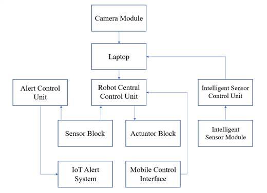
This subsection presents the overall system architecture and provides a functional description of each major hardware and software block in the proposed robotic system (Fig. 1), together with the communication methods employed among them.
The camera module is implemented using an ESP32-CAM, which is responsible for capturing real-time visual information from the robot’s environment. The ESP32-CAM is programmed using the Arduino IDE to configure image acquisition and to establish a video streaming server. The captured video stream is transmitted to the Laptop via Wi-Fi using an HTTP-based streaming protocol. No image processing is performed on the ESP32-CAM; it only provides raw image data for external processing.
The Laptop serves as a high-level processing unit for both vision-based perception and environment mapping. Python-based software developed in PyCharm is used to receive the video stream from the ESP32-CAM via Wi-Fi (HTTP stream) and perform fire detection using a YOLOv8 deep learning model. In addition, the Laptop receives LiDAR data from the Intelligent Sensor Control Unit and performs simultaneous localization and mapping (SLAM) to generate a two-dimensional map of the environment. Detection results and high-level status information are transmitted to the Robot Central Control Unit via wireless communication for further action.
The Robot Central Control Unit is implemented using an ESP32 microcontroller and functions as the main real-time controller of the robot. It receives control commands from the Mobile Control Interface via Bluetooth communication and high-level information from the Laptop via wireless communication. The ESP32 processes distance sensor data for obstacle avoidance and generates control signals for the robot’s actuators. This unit is responsible for motion control and mechanism actuation. The control logic of the ESP32 is developed and deployed using the Arduino IDE, where real-time tasks such as motor control, sensor reading, and actuator coordination are implemented.
The Alert Control Unit is implemented using an ESP32-C3 microcontroller and is responsible for processing fire and gas detection signals and generating warning information. When a hazardous condition is detected, this unit activates an audio alert and forwards warning data to the IoT Alert System via Wi-Fi. The ESP32-C3 operates independently from the robot motion control system.
The sensor block consists of flame sensors, gas sensors, and distance sensors. Flame and gas sensors are dedicated to fire and gas leakage detection for safety monitoring, while distance sensors are used for obstacle detection during robot navigation. Sensor data are transmitted to the Robot Central Control Unit through analog and digital GPIO interfaces. In addition, fire- and gas-related sensor data are forwarded to the IoT Alert System for remote warning purposes.
The actuator block includes DC 550 geared motors for robot locomotion and servo motors for controlling the rotational axes of the water spraying and powder spraying mechanisms. The DC motors provide sufficient torque for robot movement, while the servo motors enable precise angular positioning of the spraying nozzles. All actuators are driven by the Robot Central Control Unit using PWM control signals.
The IoT Alert System is implemented using the E-RA platform and is dedicated to remote monitoring and warning notification. It receives fire and gas alert data transmitted from the Alert Control Unit (ESP32-C3) and delivers warning messages to users through an internet-based connection. This system operates independently from the robot control loop and does not send control commands to the robot.
The mobile control interface is implemented as a smartphone application that serves as a human–machine interface. It allows users to manually control robot movement and firefighting mechanisms in manual mode, as well as to switch the robot to automatic mode. Control commands are transmitted to the Robot Central Control Unit via Bluetooth communication, ensuring low-latency operation. The mobile application is developed using the MIT App Inventor platform.
The intelligent sensor module refers to the LiDAR sensor, which provides distance measurements of the surrounding environment. The LiDAR generates raw scan data used for environment perception and mapping. It does not perform onboard processing and relies on external units for data handling and analysis.
The Intelligent Sensor Control Unit is implemented using a Raspberry Pi 4 and functions as an interface between the LiDAR sensor and the Laptop. The Raspberry Pi 4 operates on the Ubuntu operating system and utilizes the Robot Operating System (ROS) framework to handle sensor communication and data transmission. Raw LiDAR data are acquired via serial or USB interfaces and forwarded to the Laptop in real time, where SLAM algorithms are executed for environment mapping. Through the integration of Ubuntu and ROS, the Raspberry Pi 4 ensures reliable data flow and seamless interoperability between the LiDAR sensor and the higher-level processing unit, contributing to a stable and modular system architecture.
The proposed system adopts a distributed processing architecture consisting of an ESP32, an ESP32-C3, a Raspberry Pi 4, and a laptop to separate perception, mapping, communication, and control tasks. The laptop performs high-level image processing and YOLOv8 inference, which requires high computational capability. The Raspberry Pi 4 is dedicated to SLAM processing and LiDAR data handling for trajectory mapping and environment visualization. The ESP32 and ESP32-C3 handle sensor acquisition, actuator control, and wireless IoT communication, enabling low-latency and stable real-time operation. This distributed design allows parallel execution of tasks, reduces the computational burden on each unit, improves system modularity, and enhances overall reliability.
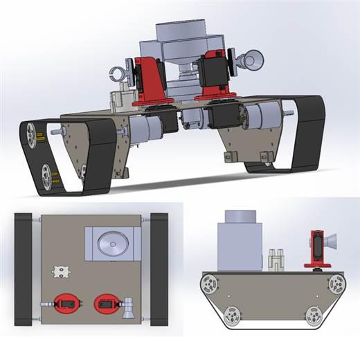
The SolidWorks drawings (Fig. 2) illustrate several components of the robot, in which the main frame is fabricated from steel using laser cutting and bending processes, while the remaining components of the powder and water spraying mechanisms, as well as the wheels, are manufactured using 3D printing.
The drive system must deliver sufficient torque to move the robot under normal operating conditions. The required traction force is estimated using the (1):
| (1) |
where m is the total mass of the robot (15 kg), g is the gravitational acceleration (9.81 m/s²), μ is the friction coefficient of the tracked system, which was set to μ = 0.5, corresponding to typical tracked mechanisms operating on indoor floor surfaces.
The total driving torque required at the drive sprocket is calculated as:
| (2) |
where T is the total required driving torque (N·m),  is the radius of the drive sprocket (0.03 m).
By substituting the above values into (1) and (2), the total required driving torque is approximately 2.21 N·m. Since the robot employs four DC motors, the required torque per motor, including a safety factor 𝐾 of 1.5 (which lies within the commonly accepted range of 1.3–2.0 for mobile robotic systems with moderate dynamic loads, in order to ensure reliable operation under variable traction and contact conditions of the tracked mechanism), is determined as:
| (3) |
Thus, the required torque per motor is approximately 0.83 N.m, which is well within the torque capability of the selected DC 550 geared motors, ensuring reliable operation under load. The selected DC 550 motors are equipped with an integrated reduction gearbox with a gear ratio of 506:1, which amplifies the motor output torque and delivers sufficient driving torque at the sprocket shaft. The gearbox is directly coupled to the tracked drive system, eliminating the need for additional transmission mechanisms.
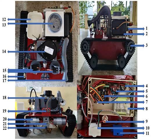
This section presents the experimental robot prototype together with the main hardware components employed in the system. The experimental robot prototype is illustrated in
Fig. 3, and the main hardware components of the robot are summarized in Table 1.
The robot is powered by a 3S battery pack composed of nine 18650 lithium-ion cells, providing a nominal system voltage of approximately 11.1–12.6 V. A DC–DC buck converter (LM2596) is used to regulate the supply to stable 5 V and 3.3 V levels for the microcontrollers and sensors. The L298 motor driver controls the DC motors and isolates high-current loads from the control electronics. Power MOSFETs are employed as electronic switches for high-current actuators and extinguishing modules to improve switching efficiency and reduce heat dissipation. Decoupling capacitors are added to suppress voltage ripple and motor noise, while transistors are used to drive low-power peripherals and alarm modules, ensuring stable voltage regulation and protection for sensitive components.
The following figures (Fig. 4, Fig. 5, and Fig. 6) illustrate the circuit design of the robotic system, detailing the connections between the microcontrollers, sensors, actuators, and other electronic components.
No | Name | Function |
1 | Raspberry Pi 4 | Processing unit for SLAM and LiDAR data handling |
2 | Power Bank Module | Power supply for the Raspberry Pi 4 and ESP32-C3 |
3 | Tracked Wheels and Sprockets | Robot locomotion and traction |
4 | Centrifugal Fan Motor | Powder dispersal for fire suppression |
5 | L298 H-Bridge Driver | Bidirectional control of DC motors |
6 | LM2596 Buck Converter | Voltage regulation for system power supply |
7 | ESP32 | Main microcontroller for robot control, actuator driving, and system coordination |
8 | 18650 Li-ion Battery | Main energy storage for the robot |
9 | 12V DC Pump | Water delivery for fire extinguishing |
10 | ESP32-C3 | Microcontroller dedicated to the warning and alert subsystem |
11 | MP3 Audio Module | Audio warning and alert playback |
12 | Plastic Tank | Water storage for the fire extinguishing system |
13 | 3D-Printed Container | Storage of fire extinguishing powder |
14 | LDS-006 LiDAR | Distance sensing for environment scanning and mapping |
15 | MG996 Servo Motor | Actuation of spraying mechanism axes |
16 | Spray Nozzle | Directs and disperses water toward the fire for extinguishing purposes |
17 | Discharge Nozzle | Guides and disperses fire extinguishing powder toward the fire source |
18 | MQ-2 Gas Sensor | Gas leakage detection for safety alerts |
19 | HC-SRF04 Distance Sensor | Measures distance to obstacles for collision avoidance and navigation |
20 | JGB37-550 DC Geared Motor | Tracked wheel drive providing high output torque |
21 | ESP32-CAM | Captures images and video for fire detection |
22 | Flame Sensor | Fire detection for warning purposes |
The algorithm flowchart (Fig. 7) presents the overall control logic of the robot, including navigation, obstacle avoidance, fire detection, alert notification, and fire extinguishing actions. It provides an intuitive overview of how the robot reacts to environmental conditions and supports the explanation of the control methods described in the following sections.
You Only Look Once (YOLO) is a one-stage deep learning–based object detection framework that performs classification and localization within a single neural network, enabling real-time detection with high computational efficiency. Owing to its fast inference speed and competitive accuracy, YOLO has been widely adopted in embedded vision and mobile robotic applications.
In this study, YOLOv8 is employed as the deep learning model for vision-based fire detection. Its anchor-free architecture and decoupled detection head improve localization accuracy and robustness in complex environments. The trained YOLOv8 model is integrated with OpenCV for real-time image acquisition and post-processing, allowing the system to detect fire regions and extract positional information for subsequent robot control.
Roboflow is an integrated platform designed to support computer vision developers in data collection, preprocessing, and model preparation. It provides a wide range of publicly available datasets while also allowing users to upload and manage their own custom image collections. In this work, Roboflow is utilized for dataset annotation, enrichment through augmentation, and dataset organization to ensure high-quality inputs for model training.
The overall workflow includes the following steps:
To develop a reliable fire detection model, a dataset was constructed from multiple sources, including public fire image repositories, open-access datasets, extracted video frames, and manually captured images under different lighting conditions, backgrounds, and fire intensities. This diversity improves the generalization ability of the YOLOv8 model and reduces training bias. All collected images were subsequently imported into the Roboflow platform for annotation and preprocessing.
After uploading the dataset to Roboflow, we manually label each image according to the Class created earlier. For this dataset, we create one Class: fire.
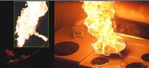
There are two commonly used labeling methods in Roboflow: labeling according to the bounding box or embracing the entire object, as shown in Fig. 8.
Training Set: is the training set.
Validation Set: is the validation data set, which helps to find the best model among the candidates trained from the training set. It also helps to limit overfitting by using the early stopping technique.
Testing Set: is the test set to evaluate the results obtained by the prediction model.
We define steps that are performed on all images before they are fed into the model. For example, you can resize your images so they are all the same size or convert your images to grayscale.
We chose to resize the data to 512×512 for ease of training the network, as shown in Fig. 9.
To add more images to the dataset, we use the tools
available on Roboflow. For example, if we want to flip the image, rotate the image, blur the image, ... on Roboflow, each tool can help us double or triple the available dataset. Some data enhancement techniques that we used:
At this step, the number of enhanced images depends on the user. We choose 2x, which means that from the training image set, Roboflow will create 2 copies and randomly apply image enhancement techniques to the copies. After the augmentation process, the final dataset consists of 2290 images, including 1978 training images, 255 validation images, and 57 testing images.
Finally, the dataset is downloaded to the computer, ensuring that the “Image and Annotation Format” option is set to YOLOv8.
Although the dataset includes various fire appearances, certain limitations remain. The detection performance may be affected in smoke-only scenes without visible flames and in environments containing reflective surfaces or strong light sources that may generate fire-like patterns and lead to false alarms. These limitations indicate that further dataset expansion and more diverse training samples are required to improve robustness in complex real-world scenarios.
Model training was conducted using Google Colaboratory (Google Colab), a cloud-based Jupyter Notebook environment that provides free access to GPU (Graphics Processing Unit) resources and pre-installed deep learning libraries, thereby eliminating the need for local hardware installation and configuration. This platform enables stable training, convenient dataset management through Google Drive integration, and efficient utilization of GPU acceleration for deep learning workloads.
After dataset preparation and annotation, the dataset was organized into training, validation, and testing subsets containing 1978, 255, and 57 images, respectively, with a single target class “fire”. All images were resized to a fixed resolution of 512×512 pixels to ensure consistency in network input dimensions.
The training process was implemented using the Ultralytics YOLOv8 framework. A lightweight pretrained detection model, YOLOv8n, was selected as the base architecture due to its compact network structure, low computational complexity, and suitability for real-time deployment on resource-constrained embedded platforms such as the ESP32-CAM and Raspberry Pi. Transfer learning was employed by initializing the network weights from the pretrained yolov8n.pt checkpoint, allowing faster convergence and improved generalization on the custom fire detection dataset.
During training, the dataset configuration was defined through a YAML file specifying the training and validation image paths, the number of classes, and the corresponding class labels. The model was trained for 50 epochs with an input image size of 512×512 pixels. The default optimization configuration provided by the Ultralytics framework was adopted to ensure training stability and reproducibility. In this configuration, the Stochastic Gradient Descent (SGD) optimizer was employed with an initial learning rate of 0.01, a momentum of 0.937, and a weight decay of 0.0005. The batch size was automatically adjusted to 16 based on the available GPU memory.
Throughout the training process, both training loss and validation performance were continuously monitored. The model checkpoint achieving the highest validation accuracy was automatically selected and saved as the final trained model (best.pt). This strategy prevents overfitting and ensures that the selected model corresponds to the best generalization performance on unseen data.
After training completion, the selected model was converted into the ONNX (Open Neural Network Exchange) format to facilitate cross-platform deployment and efficient inference on embedded devices. This conversion enables compatibility with multiple inference engines and accelerates real-time fire detection performance in the proposed robotic system.
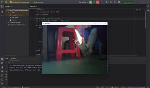
To deploy the trained YOLOv8 model for real-time fire detection, PyCharm was used as the development environment to implement the inference and monitoring pipeline. The ESP32-CAM module continuously captures video frames and transmits the live video stream to the processing unit via an HTTP-based communication protocol (Hypertext Transfer Protocol). The received frames are processed in real time using a Python program developed with OpenCV and the Ultralytics YOLO framework.
For each incoming frame, the YOLOv8 model performs fire detection and outputs bounding box coordinates together with confidence scores. A detection confidence threshold of 0.7 is applied to filter low-confidence predictions and reduce false alarms. When a fire region is detected, the center position and size of the detected bounding box are computed and transmitted back to the microcontroller through HTTP requests.
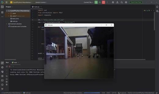
At the same time, the processed video stream with overlaid detection results is displayed on the monitoring interface (as shown in Fig. 10 and Fig. 11), allowing operators to visually supervise the detection process in real time. This distributed processing architecture separates image acquisition, deep learning inference, visualization, and control communication, thereby improving system modularity, stability, and real-time performance of the proposed fire detection pipeline.
The mobile application for controlling the multifunctional firefighting robot was developed using the MIT App Inventor platform and communicates wirelessly with the ESP32 controller via Bluetooth. The application provides two operating modes, including manual mode and autonomous mode, enabling flexible supervision and control of the robot during fire response operations.
In manual mode, the application transmits predefined control commands to the robot through a Bluetooth-based communication protocol. Each user action on the interface generates a corresponding character-based command, which is sent to the ESP32 controller to regulate robot locomotion, activate the powder and water extinguishing mechanisms, and adjust the orientation of the spraying module in real time.
In autonomous mode, after autonomous operation is enabled, the robot moves forward by default while continuously monitoring obstacle distances using ultrasonic sensors. When an obstacle is detected at a distance smaller than 18 cm, the robot stops and moves backward, then compares the distances measured by the left and right sensors to turn toward the direction with a larger clearance. For fire handling, the robot continuously analyzes the camera stream using the YOLO-based detector. When a flame is detected, the robot adjusts its heading to center the flame in the image frame and gradually approaches the target. Once the detected flame region reaches a predefined size threshold, indicating a sufficiently close distance, the robot stops and activates the extinguishing mechanism.
The Bluetooth communication channel supports bidirectional data transmission between the smartphone and the robot controller for real-time command delivery and status monitoring. This mobile control interface (Fig. 12) enables intuitive human–robot interaction and enhances system flexibility by combining autonomous operation with optional manual intervention during emergency scenarios.
The IoT-based fire and gas alert subsystem is implemented on an ESP32-C3 microcontroller, which is responsible for acquiring sensor signals, performing local alarm processing, and transmitting hazard information to a cloud-based monitoring platform. The flame sensor and gas sensor are continuously sampled, and the embedded firmware determines the alarm state based on the sensor responses. When a hazardous condition is detected, the controller activates a local audible warning through the MP3 module and simultaneously transmits alarm data to the cloud server for remote notification.
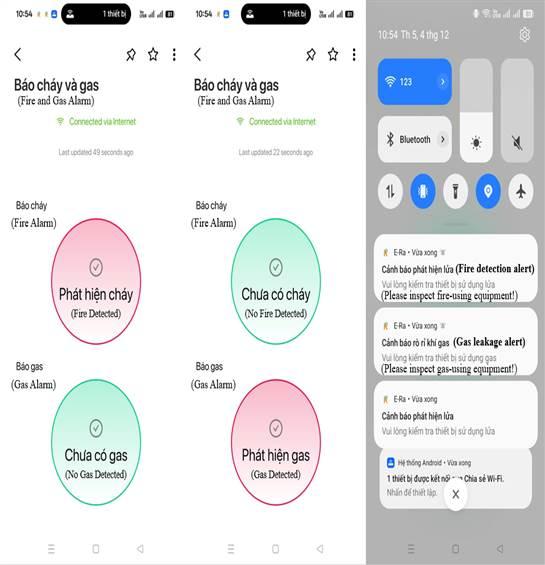
Communication between the ESP32-C3 and the E-RA IoT Platform is implemented using the MQTT (Message Queuing Telemetry Transport) protocol, enabling efficient and low-latency data transmission for real-time emergency monitoring. Sensor alarm states are transmitted as authenticated digital messages to cloud-based virtual data channels, which update the monitoring dashboard and trigger automated notification services in real time. When an alarm event occurs, warning messages are delivered to mobile devices through the IoT platform, application interface is shown in Fig. 13, allowing users to remotely monitor the system even without direct visual access to the robot. The end-to-end delay, including sensor acquisition, wireless transmission, cloud processing, and mobile notification delivery, is typically within a few seconds, ensuring timely alerts for early-stage fire and gas incidents.
To enhance system robustness, the embedded controller continues to operate locally in the event of temporary network disconnection. In such situations, the on-board audible alarm remains active to provide immediate warnings at the deployment site. Once network connectivity is restored, the system automatically resumes data synchronization and cloud-based notification services without manual intervention.
Basic security mechanisms are incorporated through platform-level authentication using access tokens and user credentials to prevent unauthorized device connections. Data integrity is maintained through structured message transmission and server-side validation before triggering notification events. These measures ensure reliable, secure, and low-overhead remote alerting, making the proposed IoT subsystem suitable for real-time fire emergency monitoring in both domestic and industrial environments.
To generate a trajectory map and provide environmental visualization, a 2D SLAM subsystem is implemented using a Raspberry Pi 4 equipped with an LDS-006 LiDAR sensor, while a laptop computer is used for SLAM processing and visualization. Both devices run Ubuntu and ROS Noetic to ensure stable communication and compatibility within the ROS framework.
The Hector SLAM algorithm is selected due to its robustness in indoor environments and its ability to operate without wheel odometry, relying primarily on high-frequency LiDAR measurements for pose estimation. Laser scan data acquired by the LiDAR sensor are transmitted to the processing unit, where scan matching techniques are applied to incrementally estimate the robot’s pose and reconstruct an occupancy grid map of the surrounding environment. The map resolution is configured at approximately 5 cm per grid cell, providing a suitable compromise between spatial accuracy and computational efficiency. The mapping process operates at an update rate of about 5–10 Hz, enabling near real-time trajectory visualization.
In the proposed system, the SLAM module is employed exclusively as a monitoring and visualization tool rather than as a navigation or motion-planning component. The robot’s autonomous movement and obstacle avoidance are controlled independently by onboard distance sensors and low-level control algorithms. This design choice reduces computational load and improves system robustness while still providing valuable spatial information for situational awareness.
The resulting trajectory and occupancy grid map are visualized in real time through the monitoring interface (Fig. 14), allowing operators to observe the robot’s motion and surrounding environment during fire detection and emergency response. By limiting the role of SLAM to mapping and visualization, the system maintains reliable autonomous operation while enhancing environmental awareness without compromising real-time performance.
Based on the successfully developed hardware and software system and the identified limitations, multiple experiments were conducted to validate the effectiveness of the proposed approach, and the corresponding results are presented in the following experimental results section.
To comprehensively evaluate the proposed robotic system, the experimental results are divided into several test categories covering image-based fire detection, robot operation and mobile application control, alert functionality, SLAM-based mapping performance, and the overall system operation. These experiments aim to verify the effectiveness, reliability, and integration of all system components under practical operating conditions.
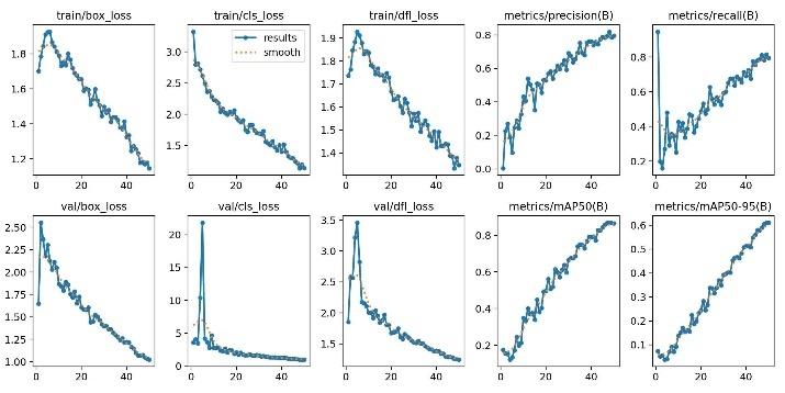
After YOLO's training is complete, we get a folder containing images of the training results, as shown in Fig. 15. Fig. 15 illustrates the loss and metric trends during the training and validation of the YOLOv8 model. The training results indicate that the YOLOv8 model converges stably throughout the learning process. The loss components, including box loss (bounding box localization loss), classification loss (object classification loss), and distribution focal loss (DFL, which is used to improve bounding box regression accuracy), gradually decrease over the training epochs on both the training and validation sets. This behavior demonstrates effective learning and indicates that no significant overfitting occurs.
Regarding detection performance, both precision (the ratio of correct predictions to the total number of predictions) and recall (the ratio of correctly detected objects to the total number of ground-truth objects) increase steadily and reach approximately 0.80. These results indicate that the proposed model is capable of accurately detecting fire events while effectively reducing false alarms and minimizing missed detections.
Furthermore, the model achieves an mAP50 (mean Average Precision at IoU = 0.5) of approximately 0.87 and an mAP50–95 of about 0.61. These metrics confirm that the model not only recognizes fire regions reliably but also localizes them with relatively high accuracy under various intersection-over-union thresholds. Therefore, the proposed YOLOv8 model satisfies the performance requirements for deployment in autonomous fire-fighting robots and early fire warning systems.
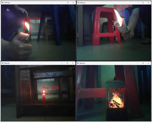
The fire detection was tested with various types of flames, such as lighter flames, candle flames, and flames from burning paper, yielding promising results, as shown in Fig. 16.
The fire detection experiments were conducted under different environmental lighting intensities and fire area sizes. The ambient illumination was categorized into three levels, namely low lighting (50–150 lux), medium lighting (300–500 lux), and strong lighting (above 800 lux), corresponding to dim indoor conditions, normal room illumination, and strong artificial or outdoor lighting, respectively. The fire area was also divided into three levels based on the estimated flame region area, where Level 1 corresponds to an area smaller than 2 cm², Level 2 corresponds to an area between 2 cm² and 5 cm², and Level 3 corresponds to an area larger than 5 cm². The success rate of fire detection under each condition is summarized in Table 2.
Environmental Lighting Condition | Fire Area Size | Successful Detection Rate (%) |
Low light | Level 1 | 92 |
Level 2 | 97 | |
Level 3 | 100 | |
Normal Light | Level 1 | 80 |
Level 2 | 87 | |
Level 3 | 92 | |
Strong Light | Level 1 | 50 |
Level 2 | 60 | |
Level 3 | 75 |
From the experimental results, it can be observed that the proposed YOLO-based model achieves higher detection accuracy under low lighting conditions. This behavior can be attributed to the increased contrast between the flame region and the background when ambient illumination is reduced, which facilitates the extraction of discriminative flame features by the vision model. In contrast, the detection performance degrades under strong lighting conditions due to specular reflections, background glare, and partial color saturation, which reduce the visibility of flame boundaries and increase the probability of false detections.
In addition, the results indicate that larger fire areas are easier to detect, as the increased flame region provides richer visual cues, leading to more stable bounding box regression and higher confidence scores. Conversely, very small fire regions (area < 2 cm²) contain limited visual information and are more sensitive to illumination variations and background interference. To mitigate the performance degradation under strong lighting conditions, future work may incorporate multi-sensor fusion with infrared or thermal cameras, apply infrared filtering to suppress background glare, adopt dynamic confidence thresholds adapted to illumination levels, and enrich the training dataset with additional samples collected under high-intensity lighting environments. Overall, the experimental results demonstrate that the proposed fire detection system performs reliably under low-light conditions and exhibits improved detection accuracy as the fire area increases.
After successfully establishing a Bluetooth connection with the robot, the mobile control application operates reliably in both autonomous and manual modes. In autonomous mode, the robot is able to navigate smoothly and effectively avoid obstacles based on sensor feedback, achieving an obstacle avoidance success rate of approximately 90% with an average navigation time of 5.4s per trajectory and an average turning accuracy of 92%. The response latency of the control system in autonomous mode is measured to be approximately 120 ms, ensuring stable real-time navigation performance.
In manual mode, the robot responds promptly to user commands with an average response latency of about 100 ms, allowing stable and precise control. The command execution success rate reaches 100%. Experimental results further confirm that the robot can successfully perform firefighting tasks using both water spraying and powder discharge mechanisms, with an overall task completion success rate exceeding 98%, demonstrating the effective and reliable operation of the proposed robotic firefighting system.
The robot is capable of operating on slopes below 20° and in environments with non-severely uneven terrain. Bluetooth communication between the mobile phone and the microcontroller is stable, and control actions are executed almost immediately after the user presses the corresponding buttons on the interface. The robot control interface after establishing the connection is illustrated in Fig. 17, while the firefighting operations using powder discharge and water spraying are shown in Fig. 18 and Fig. 19.
After a successful Wi-Fi connection is established, the mobile application continuously receives real-time signals from the ESP32-C3. Under the experimental conditions, the wireless communication operates reliably without unexpected disconnections or transmission failures. When the robot approaches a fire source within a distance range of approximately 60–100 cm, the flame sensor is activated to trigger the MP3 module, generating an audible warning, while a notification message requesting inspection of fire- or gas-using equipment is simultaneously transmitted to the user’s mobile phone. The average time interval from fire detection to alert reception is approximately 2.5 s, demonstrating that the proposed IoT-based warning system is able to provide timely notifications. The E-Ra application interface (Fig. 20) also displays corresponding fire and gas detection alerts in a stable and consistent manner.
However, under environments with strong ambient lighting, the flame sensor may exhibit delayed responses or occasional false alarms. This limitation is mainly caused by high-intensity light sources, such as sunlight or halogen lamps, which emit infrared radiation within a wavelength range similar to that of a real flame. As a result, strong illumination may be misinterpreted as a flame signal, leading to inaccurate detections and redundant notifications. These results indicate that although the proposed wireless communication and IoT alert system performs reliably under the tested conditions, its robustness can be further improved by incorporating infrared filtering, adaptive detection thresholds, sensor fusion techniques, and more comprehensive communication performance measurements in future work.
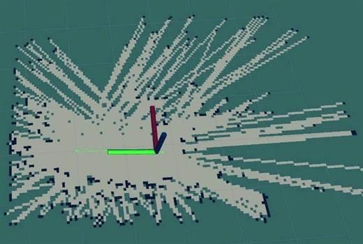
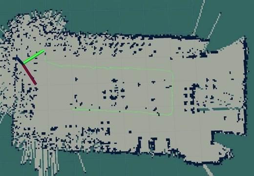
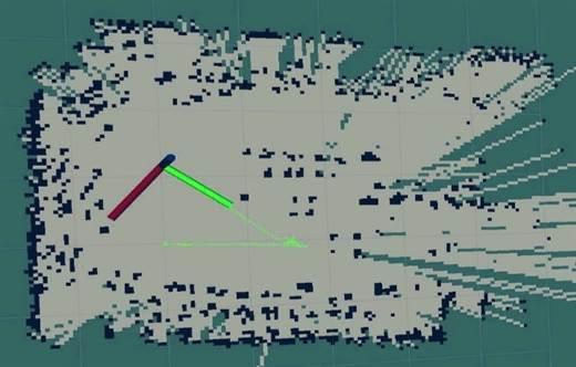
The SLAM performance was evaluated by allowing the robot to move along a predefined trajectory at three PWM-based speed levels while recording the generated two-dimensional (2D) maps. In the first experiment, the robot moved in a straight line at a speed with PWM=100, and the resulting 2D map accurately represented the traveled path with a mean positional deviation below 2 cm, as shown in Fig. 21. In the subsequent experiments, the robot navigated around a rectangular-shaped room at three different speed levels. At the lowest speed (PWM = 80), the generated map showed clear room boundaries with an average localization error of approximately 2–4 cm. At the medium speed (PWM = 130), slight distortions were observed at turning points, and the average mapping error increased to about 5–7 cm. At the highest speed (PWM = 180), significant localization drift and map deformation occurred, with errors exceeding 20 cm, indicating a clear degradation of mapping reliability beyond this speed threshold. The robot trajectory and the mapping results are shown in Fig. 22, Fig. 23, Fig. 24, and Fig. 25.
These errors are mainly attributed to wheel slippage, accumulated odometry errors, and sensor update latency at higher PWM values. It should be noted that, in the proposed system, the 2D SLAM module is used only for environment monitoring and visualization and does not directly affect the robot navigation, fire detection, or firefighting operations. Therefore, the degradation of mapping accuracy does not influence the core detection and suppression performance. However, inaccurate maps may reduce the situational awareness of the remote operator and limit the effectiveness of environment observation during emergency monitoring. To address this limitation, future work will consider adaptive speed control to limit excessive motion during mapping, as well as sensor fusion techniques combining odometry, inertial measurements, and LiDAR data to enhance 2D mapping accuracy and visualization reliability.
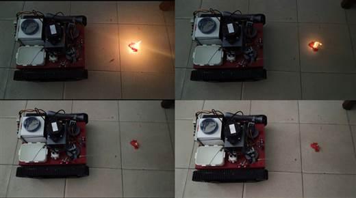
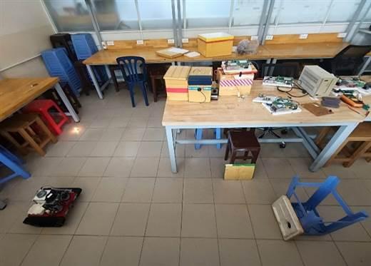
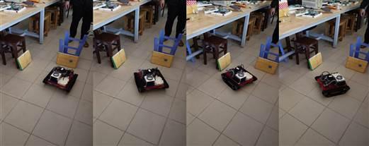
The experimental setup was implemented in an indoor environment with obstacles and a candle flame, as illustrated in Fig. 26. After the automatic mode was activated by pressing the corresponding button on the mobile control application, the robot started autonomous navigation while avoiding obstacles at a medium speed (PWM=130). When an obstacle was detected, the robot moved backward and adjusted its direction by approximately 90° and continued moving forward. Once a fire source was detected, the robot continuously corrected its heading to keep the flame centered in the ESP32-CAM image frame and moved straight toward the fire. At the same time, an alert notification was sent to the user’s mobile phone through the E-Ra application. Upon reaching the target area, the fire extinguishing mechanism was activated, and the fire was successfully suppressed. Meanwhile, the SLAM algorithm recorded the robot’s trajectory and reconstructed the map of the environment, illustrating the complete navigation and intervention process. The obstacle avoidance and fire extinguishing process is shown in Fig. 27 and Fig. 28, while the generated map with an error smaller than 7 cm is presented in Fig. 29.
The fire extinguishing performance was evaluated through ten experimental trials conducted. For each trial, the lateral deviation between the robot center and the flame center, the stopping point error relative to the predefined target distance of 20 cm in this experimental setup, and the total fire extinguishing time were recorded. The stopping point error was defined as negative when the robot stopped closer than the target distance and positive when it stopped farther than the target. The experimental results are presented in Table 3.
Across all trials with available data, the mean lateral deviation was 1.03 cm, the mean stopping point error was 1.76 cm, and the average fire extinguishing time was 20.7 s, indicating that the robot generally approached and stopped near the desired target position. The best performance was achieved in Trial 2, with zero lateral deviation, zero stopping point error, and the shortest extinguishing time of 15 s, demonstrating accurate positioning and efficient suppression under optimal conditions.
Three unsuccessful cases were observed during the experiments. In the third trial, the fire could not be completely extinguished because the extinguishing material (water or powder) was depleted before suppression was completed. In the sixth trial, unstable and flickering flames caused the image-based fire detection module to fail, resulting in the robot passing through the fire area without activating the extinguishing mechanism. In the ninth trial, excessive lateral deviation prevented effective fire suppression, leading to an unsuccessful extinguishing attempt.
The results indicate that both lateral deviation and stopping point error strongly affect suppression effectiveness. Accurate alignment and stopping close to the target distance improve extinguishing performance and safety margins. In the current experiments, the spraying angle was set to approximately 70°, and reducing this angle to about 40° is expected to further improve suppression efficiency and reduce lateral dispersion in future implementations.
Compared with several autonomous firefighting platforms reported in previous studies [1], [2] that mainly demonstrated qualitative suppression capability without detailed statistical evaluation, the proposed system achieves a comparable overall success rate while providing quantitative performance indicators such as extinguishing time, lateral deviation, and stopping error. In these previous works, fire detection and obstacle avoidance were primarily implemented using flame sensors and infrared sensors, while the camera was mainly used for visual monitoring rather than image-based fire recognition. In addition, although mobile phone control was supported, remote alert notification and environmental mapping functions were not considered. By contrast, the proposed system integrates vision-based fire detection, autonomous navigation, IoT-based alerting, and SLAM-based monitoring, enabling a more comprehensive evaluation of system robustness and operational accuracy.
The validated strengths of the proposed system include stable navigation, accurate stopping near the target distance, and effective fire suppression under controlled indoor conditions. However, several experimental limitations were observed, including sensitivity of vision-based detection to unstable flames, material depletion during prolonged suppression, and performance degradation under large lateral deviations. In particular, suppression effectiveness decreases when the robot deviates significantly from the flame center or stops beyond the optimal target distance.
Overall, these experimental results confirm that the proposed hardware–software system successfully fulfills the research objectives of autonomous fire detection, navigation, and suppression. Despite the identified limitations, the achieved performance demonstrates the feasibility and practical applicability of the proposed methodology for early-stage indoor firefighting and robotic emergency assistance.
Trial No. | Lateral Deviation (cm) | Stopping Point Error (cm) | Fire Extinguishing Time (s) |
1 | 0.5 | -1.0 | 18 |
2 | 0.0 | 0.0 | 15 |
3 | 1.5 | -2.9 | - |
4 | 0.8 | +1.0 | 20 |
5 | 1.0 | -2.0 | 22 |
6 | - | - | - |
7 | 0.6 | +0.5 | 19 |
8 | 1.2 | +2.0 | 30 |
9 | 3.0 | +5.0 | - |
10 | 0.7 | -1.5 | 21 |
This paper presented the design and experimental validation of an autonomous firefighting robot integrating autonomous navigation, vision-based fire detection, IoT-based alert notification, and SLAM-based environmental monitoring. The main objective was to develop a low-cost robotic platform capable of detecting early-stage fires, navigating toward the fire source, issuing remote alerts, and performing basic fire suppression in indoor environments. The proposed hardware–software architecture and control strategy constitute the primary contributions of this work.
The experimental results demonstrate that the proposed methodology effectively combines autonomous navigation, image-based flame detection, wireless communication, and real-time monitoring to achieve reliable fire detection and suppression performance. The reported 70% extinguishing success rate indicates that the system is suitable for early-stage fire response or supervised deployment scenarios, where rapid detection, preliminary suppression, and remote warning can significantly reduce fire propagation and improve safety before human intervention. In particular, the proposed robot can be deployed in warehouses, parking areas, storage facilities containing hazardous or flammable materials, and enclosed spaces requiring continuous safety monitoring, where early detection and preliminary firefighting assistance are critical for preventing fire escalation and minimizing potential damage.
Nevertheless, several limitations were identified during the experiments. The fire detection performance degrades under strong ambient lighting conditions, perception failures may occur with unstable or flickering flames, and extinguishing effectiveness is constrained by limited extinguishing resources. In addition, the robot is currently unable to operate on complex terrains, lacks fire-resistant protective mechanisms, and the SLAM-based mapping accuracy remains limited, which may affect long-term monitoring and operator situational awareness.
Future work will focus on improving system robustness and practical applicability by integrating enhanced sensor fusion techniques, developing more reliable fire detection under varying environmental conditions, upgrading the extinguishing mechanisms, and incorporating obstacle avoidance and fixed-map generation using SLAM for continuous fire-safety monitoring in predefined areas. Further hardware upgrades and extensive testing in diverse and realistic environments will also be conducted to eliminate the remaining limitations and enhance system reliability.
This research was funded by Ho Chi Minh City University of Technology and Engineering (HCM-UTE), Vietnam, under grant No. SV2026-256. We also want to give thanks to Assoc. Ph.D. Minh-Tam Nguyen (HCM-UTE), due to his supervision. We, authors, are grateful for this support. Link of operation of the system is shown in the link: https://www.youtube.com/watch?v=q-QBT4b5JoA.
Hoang-Thong Nguyen, Design and Implementation of an IoT-Enabled Autonomous Fire-Fighting Robot Using Vision-Based Fire Detection