Journal of Fuzzy Systems and Control, Vol. 4, No 1, 2026 |
Design and Simulation of DC-AC Power Converters
Salam Waley Shneen 1,*
1 Energy and Renewable Energies Technology Center, University of Technology, Baghdad, Iraq
Email: 1 salam.w.shneen@uotechnology.edu.iq
*Corresponding Author
Abstract—Currently, various types of electronic power converters are used in many fields and industrial applications, one of the most important of which is industrial power converters. They are an essential part of electrical power systems in generating stations, distribution systems, and transmission systems, through their connection to the main grid and sub-grids. Electronic power converters are used in energy generation systems from sustainable development sources, and clean energy is a good example of this. The functions of electronic power converters vary according to the need for them, including changing the type of voltage, current, and frequency, which are electrical quantities. Electronic power converters can be classified into buck, step-down, boost, and step-up. The inverter is one of the types of electronic power converters that works to convert and change the converter input from direct current to a converter output with an alternating voltage. The input of the converter is connected to a DC source such as batteries, solar power, or a DC generator, while the output of the converter supplies AC loads such as a single-phase or three-phase induction motor. The inverter can be single-phase or three-phase, depending on the load to be supplied, and it can be a half-wave or full-wave bridge. The study contributes to implementing and setting appropriate design steps, in addition to building a simulation model to determine the system's behavior during a specific operating period.
Keywords—Power Electronic Converters; DC-AC Converters;1-ph DC-AC Converters; Half Wave Bridge; Full Wave Bridge
Electrical and electronic devices are essential to many aspects of life in all countries worldwide, and people use them in numerous daily applications. Household applications include televisions, water pumps, computers, air conditioners, lighting, refrigeration and air conditioning units, and more. There are also industrial, agricultural, medical, and other applications. Electrical and electronic devices operate at a specific level of performance when used for a particular function [1], [2]. Electrical energy is generated as alternating current (AC) or direct current (DC), depending on the power source, and it can be converted from AC to DC and vice versa. Various devices operate by being supplied with an electrical power source, such as the main grid, a DC or AC generator, or renewable energy sources like solar and wind power [3], [4]. One or more power sources can be available wherever an electrical or electronic device needs to operate. Electrical devices are considered loads that require power from either an AC source, such as a diesel generator, the grid, wind power, or others, or a DC source, such as batteries, photovoltaic (PV) systems, or others [5], [6].
There are two main types of converters. The first type converts the input voltage from DC to AC and is called an inverter. It is used when the power supply is DC, such as a solar power source, and the load is AC. The inverter is connected between the load and the power supply [7], [8]. The second type of converter is called a rectifier. Its function is the opposite of an inverter. It is used when the available voltage is AC while the load requires DC, such as running a DC motor. There are also two other types: AC converters and DC converters. The first type is a boost converter, the second is a step-down (buck) converter, and the third is a buck - boost converter [9], [10].
Several concepts can be introduced to help identify the system and its function. These concepts are crucial when building and mathematically representing the system, creating simulation models, and during proposed tests. One such concept is voltage transfer gain (VTG), which represents the difference between the input and output of the transformer. Its maximum value, called the maximum voltage transfer gain, can be measured. Calculating VTG is one of the most important performance indicators for a transformer. Another concept is duty cycle (DR), which can also be calculated depending on the transformer type. A further indicator is efficiency, or maximum efficiency, denoted by (ɳ%). The first indicator, gain, is a key factor in the use of transformers in many applications [11], [12]. The operation of electronic switches, the control technology used in the transformer, and the selection of appropriate inductors and capacitors all affect the transformer's performance. The current work is distinguished by its study of the power converter in renewable energy (RE) applications, specifically photovoltaic (PV) energy sources, where it presents and discusses the benefits and methodology for identifying
how to obtain gain, increase efficiency, and improve performance [13], [14].
The current study aims to identify a type of inverter by defining the load and power source. As a research contribution, a converter is designed to meet load requirements while minimizing costs and enhancing performance in terms of quality, reliability, and efficiency. Furthermore, tests are proposed by constructing a simulation model based on the mathematical representation of the system. The system's effectiveness and potential for improvement are verified through the proposed test results, which are conducted over a period of operation under various conditions that mimic real-time operating scenarios and are suitable for a wide range of applications.
DC-AC converters, when the source voltage differs from the required load voltage, a suitable voltage transformer is connected to provide the necessary voltage for the load. An inverter converts direct current (DC) to alternating current (AC). For example, a source voltage inverter supplies an AC load from a DC source after conversion using a source voltage inverter-type converter [15], [16]. The converter design depends on the electrical quantities, such as the supplied input voltage and the required output voltage. The voltage regulation technique is selected by controlling the switching intervals of the transformer's electronic switches at a specific periodic frequency, according to the required output. This study aims to build an efficient system that performs its function with high quality and reliability, ensuring stable performance by focusing on appropriate voltage boost requirements, increasing the required voltage transmission gain, and improving efficiency. The study also aims to simulate operating conditions compatible with various electronic system applications in real time [17], [18]. The study addresses the theoretical aspects, mathematical representation, and relationships between system components to study the dynamic behavior of the system during operation through computer simulation. Tests were proposed to suit different conditions within the operating cycle range, to address output voltage fluctuations, reduce component power consumption, lower costs by minimizing losses, and simplify the system. The study presents a model designed to provide a system that operates on the basis of regulating the output voltage of the transformer,
while achieving high gain and raising the system's efficiency level [19], [20].
This study presents the construction and design of a simulation model. Studying reflectors of all kinds is an advantage for specialists because they are part of most systems. Many studies have presented the use of reflectors in many fields and applications. Also, verifying the possibility of building and designing effective models helps researchers in this field in their future studies, in addition to those experienced in the field of education or scientific guidance. The simulation results contribute to a comprehensive analysis of various inverter topologies, as well as their control and modulation techniques. The first topology is a single-phase half-wave inverter. The operating principle was analyzed and validated using MATLAB-Simulink. The second topology is a single-phase full-wave bridge inverter. The operating principle was analyzed and validated using MATLAB-Simulink. The simulation results, along with theoretical analysis, demonstrate the inverter's potential for application in many fields, including industrial applications. They also demonstrate the inverter's high quality and efficiency using control techniques.
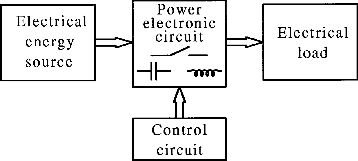
The current study aims to shed light on electronic power converters by identifying the most important types and modern technologies used to increase the efficiency of electrical systems and reduce electrical energy losses. Electronic power converters are characterized by their ability to convert from one electrical voltage value to another using electronic circuits consisting of electronic switches in the form of semiconductor devices such as thyristors and transistors (MOSFET and IGBT). Converters are characterized by their ability to regulate voltage in many applications and fields such as electronic systems for power sources, electric vehicles, and battery charging. Converters work to increase or decrease the voltage as needed. The converter is constructed and designed by selecting an electronic switch, a coil, a capacitor, and a control circuit that opens and closes the electronic switch to control the on and off periods according to the required output of the converter to meet the load requirements connected to the converter output as in Fig.1 [21]-[23].
Inverter, the voltage inverter has an input from a DC source that connects to the inverter's input terminal. A solar power source, batteries, or a DC generator, which may be connected to a wind turbine, is connected to the inverter's input terminal. The inverter is designed and built with a number of electronic switches depending on the inverter type. Some of these switches are four-way switches, while the other two-way switches are single-phase inverters. There is another three-phase type consisting of three or six switches. The first type is a half-bridge type, while the second is a full-bridge type. The inverter output can be fixed voltage and frequency or variable [24]-[26]. To control the source voltage inverter, you can use voltage control or frequency control, and you can also take the voltage-to-frequency ratio as a reference value for control. Inverter technology is the name given to modern devices that operate on the inverter principle. Modern technologies rely on relays and timers, which operate under specific conditions and shut down when those conditions change. These include refrigerators and air conditioners [27], [28]. To conserve as much energy as possible by consuming less and operating electrical appliances less, we connect sensors that sense operating conditions such as the temperature in room air conditioners and the cold in refrigerators, which makes them operate for a shorter period instead of continuously operating them, thus saving some energy [29]-[30].
The Fig. 2 represents a voltage inverter connected to a load on the output side and a power source on the input side. The figure also shows the types of switches that can be used to construct an inverter, as well as some types of loads and some types of power sources for the inverter's input terminal.
A single-phase inverter can be connected to a solar power system or to the grid with a filter, as shown in Fig. 3. Connecting a solar system to the grid requires compliance with grid safety standards, including those related to the inverter, leakage current, various techniques for separating AC from DC, and the addition of common ground configurations.
The current work presents a study to identify the inverter based on previous literature. An inverter model is constructed, and this model is used to conduct tests proposed for inverter simulation. The proposed simulation includes identifying the behavior of a single-phase inverter with half-wave and full-wave characteristics. The system is simulated to load a resistor once and a resistor and an inductor in series another time. The simulation results allow for studying the system's behavior and conducting appropriate analysis of those results.
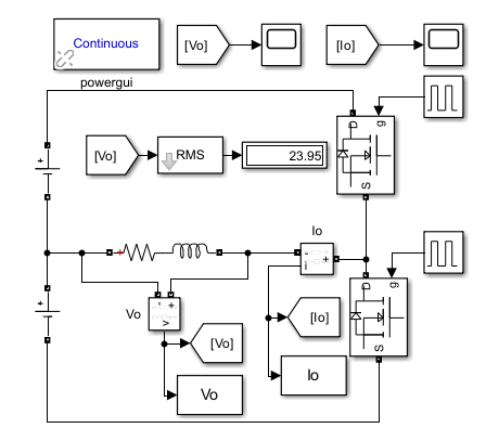
The first prototype being built for the proposed tests consists of a power supply, an inverter, and a resistive load, under the title "simulation model for single-phase inverting half-bridge-type current with two DC voltage sources and no capacitor". The system components can be identified through the components of the Simulation Model of Single-phase half-bridge inverter type one with two DC voltage sources and without a capacitor at R Load as in to Fig. 3. There are two types: Single-phase half-bridge inverter type one and Single-phase half-bridge inverter type two with DC voltage source and two capacitors as in Fig. 6.
After building the model, the operating period, source voltage, and load impedance can be determined to perform the simulation and plot the current and voltage signals of the system output, which represent the load voltage and current. By plotting the load voltage and current waveforms, they can be analyzed to identify the system behavior for this type of system under the proposed conditions.
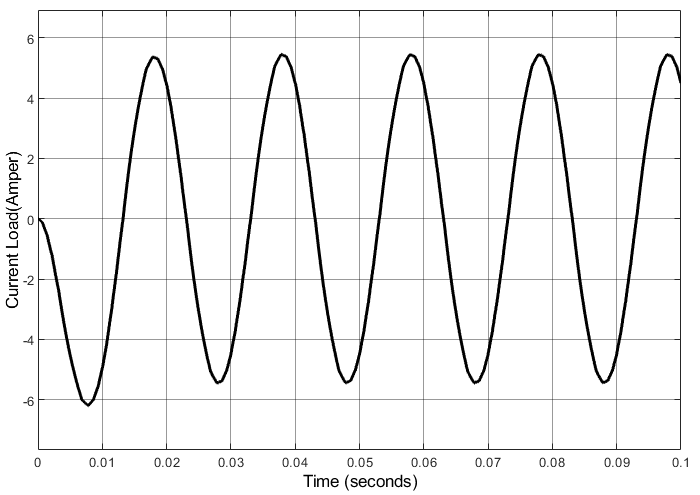
Fig. 4 shows the output voltage response in a simulated type 1 single-phase half-bridge inverter. The voltage can be read as positive 23.95 in the first half-period (0–0.01) and negative 23.95 in the second half-period (0.01–0.02). Fig. 5 shows the output current response in the simulated type 1 single-phase half-bridge inverter for both the negative and positive periods, which is approximately 5 amperes.
Fig. 6 show the simulation model of single-phase half-bridge inverter type two with DC voltage source and two capacitors. Fig. 7 shows the output voltage response in a simulated type 2 single-phase half-bridge inverter.
Fig. 8 simulation model of single-phase half-bridge inverter type one with two DC voltage sources and without a capacitor at R&L load. Fig. 9 simulation response of output current for the single-phase half-bridge inverter type one and without a capacitor at R&L load.
As in the first case, a model is built with a resistive load once, and then with a resistive and inductive load. The simulation results can then be identified and analyzed to determine the behavior of a full-wave bridge inverter system. The second type differs in the number of electronic switches and consists of four switches, as shown in the figure. In the first period, one of the upper switches is ON, and the other is OFF, while in the lower leg, one switch is ON and the other is OFF.
Fig. 10 simulation tool for full wave single phase inverter. Fig. 11 simulation model of full wave single phase inverter with R load. Fig. 12 simulation model of full wave single phase inverter with R&L load. Fig. 13 simulation response of output voltage for a single-phase full-bridge inverter type with R&L load. Fig. 14 simulation response of output current for a single-phase full-bridge inverter type with R&L load. Fig. 15 simulation response of output voltage for a single-phase full-bridge inverter type with R&L load. Fig. 16 simulation response of output current for a single-phase full-bridge inverter type with R load.
Fig. 17 to Fig. 20 show the results of a simulation test of a single-phase full-wave inverter. Fig. 17 shows the simulated output voltage response to a single-phase full-bridge inverter with an R&L load, while Fig. 18 shows the simulated output current response to a single-phase full-bridge inverter with an R&L load. Fig. 19 shows the simulated output voltage response to a single-phase full-bridge inverter with an R&L load. Fig. 20 shows the simulated output current response to a single-phase full-bridge inverter with an R load.
Further test results can be seen in Fig. 21 and Fig. 22, which represent the system's response using pulse width modulation (PWM). Fig. 21 shows the simulated output current response to a single-phase full-wave inversion using unfiltered SPWM. Fig. 22 shows the simulated output voltage response to a single-phase full-wave inversion using unfiltered SPWM.
A simulation model of a single-phase inverter with and without a filter was built and designed. The inverter was identified as either half-wave or full-wave through proposed tests, including operating it with a resistive load and then with a series-inductor load with a resistor. The conclusions drawn from the proposed research contributions included the system's efficiency. An AC voltage waveform can be obtained from a constant DC input source, while the output voltage is alternating and variable by employing electronic switching during opening and closing using pulse width modulation (PWM). Further tests can be conducted to verify the feasibility of using controllers such as conventional, expert, and intelligent systems.
Salam Waley Shneen, Design and Simulation of DC-AC Power Converters