(1)
Journal of Fuzzy Systems and Control, Vol. 4, No 1, 2026 |
A Study of a Laser Engraving System Based on a Cartesian Robot with Image Processing
Thai-Duong Hoang 1, Manh-Dung Nguyen 2,*, Chi-Phat Pham 3, Thi-Ngoc-Thao Nguyen 4, Tan-Phat Nguyen 5,
Anh-Son Tran 6, Quang-Thuan Le 7, Phuoc-Thinh Dang 8, Thai-Hiep Nguyen 9, Quang-Tung Trinh 10,
Hoai-Bao-Nhan Nguyen 11, Huu-Nhan Nguyen 12, Thanh-Binh Nguyen 13
1, 2, 3, 4, 5, 6, 7, 8, 9, 10, 11, 12, 13 Ho Chi Minh City University of Technology and Engineering (HCM-UTE), Ho Chi Minh City (HCMC), Vietnam
Email: 1211511090@student.hcmute.edu.vn, 2 211511089@student.hcmute.edu.vn, 3 20119191@student.hcmute.edu.vn,
4 thaontn@hcmute.edu.vn, 5 22146190@student.hcmute.edu.vn, 6 22144180@student.hcmute.edu.vn,
7 22144204@student.hcmute.edu.vn, 8 22146233@student.hcmute.edu.vn, 9 22146121@student.hcmute.edu.vn,
10 22146251@student.hcmute.edu.vn, 11 22146185@student.hcmute.edu.vn, 12 22146186@student.hcmute.edu.vn,
13 binhnt@hcmute.edu.vn
*Corresponding Author
Abstract—Traditional CNC laser engraving systems often face limitations in flexibility, requiring manual alignment and pre-defined G-code files. This paper proposes an advanced automated laser engraving system based on a 3-axis Cartesian robot that bridges the gap between industrial control reliability and modern computer vision. The core novelty of this research lies in the seamless integration of a Mitsubishi Q03UDE Programmable Logic Controller (PLC) with a Python-based image processing framework. By utilizing the OpenCV library for real-time edge detection and trajectory generation, the system can autonomously identify object positions and convert complex patterns into precise motion commands. Communication is established via the MC Protocol over Ethernet, ensuring high-speed data synchronization between the vision system and the servo-driven hardware. Experimental results demonstrate that the proposed system achieves high precision in engraving, significantly reduces setup time by eliminating manual calibration, and maintains the robust stability required for industrial environments. This approach provides a scalable solution for intelligent manufacturing and personalized production.
Keywords—Laser Engraving; Cartesian Robot; Mitsubishi Q03UDE; PLC; Python; Image Processing; OpenCV; MC Protocol; Industrial Automation
In the modern industrial landscape, the integration of high-precision robotics and intelligent sensing has become a pivotal factor in achieving the goals of Industry 4.0 [1]. Cartesian robots, characterized by their linear axes and robust structural frames, remain a preferred choice for material processing due to their high positioning accuracy and straightforward kinematic modeling [2], [3]. Among various applications, laser engraving has evolved from simple marking to complex surface treatments, necessitating control systems that can handle both high-speed motion and intricate path planning [4].
However, conventional laser systems often rely on static G-code generation, which lacks the flexibility to adapt to dynamic manufacturing environments [5]. To address this, the incorporation of Computer Vision (CV) has been proposed to automate object recognition and trajectory mapping [6]. Recent studies have shown that using the OpenCV library allows for efficient real-time edge detection and contour extraction, which are essential for translating visual data into robotic motion [7], [8].
While many researchers utilize microcontrollers for prototyping, the harsh conditions of industrial environments demand the reliability and electromagnetic interference (EMI) resistance of Programmable Logic Controllers (PLCs) [9]. The Mitsubishi Q-series, in particular, has been highlighted for its high-speed processing capabilities and support for advanced motion control modules [10]. Furthermore, the communication between high-level vision algorithms (Python) and low-level hardware (PLC) is a critical bottleneck. The use of Ethernet-based protocols, such as the MC Protocol, has been proven effective for low-latency data synchronization in integrated systems [11], [12].
Advanced motion control techniques, including PID tuning and closed-loop servo systems, are vital to maintaining engraving quality across different material surfaces [13]. Recent advancements in hybrid control architectures have demonstrated that combining the computational power of PCs with the stability of PLCs can significantly reduce system response time and improve engraving throughput [14]. By eliminating the need for manual alignment and pre-defined coding, such intelligent systems provide a scalable solution for personalized production and high-volume industrial tasks [15]. The primary objectives of this study are twofold: first, to implement a real-time image processing pipeline that ensures immediate classification of objects on a moving conveyor; and second, to optimize system efficiency and accuracy. By replacing manual sorting with an automated robotic solution, the system aims to mitigate human-induced errors while significantly reducing operational costs and cycle times in industrial applications [16]-[22].
The most defining property is that all axes (X, Y, Z) are perpendicular (orthogonal) to one another. This rigid 90-degree alignment simplifies mechanical design and ensures predictable motion.
Because the axes are typically supported at both ends (especially in "Gantry" configurations) rather than cantilevered like a human arm, they suffer from very little deflection. This makes them incredibly rigid.
They are modular. If you need a longer reach, you can simply use a longer rail for that specific axis without redesigning the entire robot. This is impossible with articulated arms, where extending reach requires larger motors and completely new linkage designs.
For Cartesian robots, establishing a Denavit-Hartenberg (DH) table is not strictly mandatory, as the axes align directly with the Cartesian coordinate system and involve solely translational motion. However, to maintain consistency with standard robotic kinematic conventions, the system can be modeled as a series of three prismatic joints. Table 1 presents established DH parameters for the Cartesian robot.
The forward kinematics problem determines the position and orientation of the end-effector based on known joint variables. Since the robot undergoes only translational motion and the orientation vector remains constant relative to the base frame, the general homogeneous transformation matrix T is expressed as in (1) follows:
| (1) |
Hence, the position of the end-effector is a direct result of the joint variables, represented as P =  . This linear relationship demonstrates that the motions of the X, Y, and Z axes are completely decoupled and independent of one another.
Link( |
|
|
|
|
1 | 0 | 0 |
| 0 |
2 | 0 | 0 |
| 0 |
3 | 0 | 0 |
| 0 |
The inverse kinematics problem necessitates the determination of the joint variable set(s) corresponding to a specific pose (position and orientation) of the end-effector. The aggregation of all joint values constitutes the robot's configuration within the joint space.
While deriving inverse kinematics from forward kinematics presents significant computational challenges for articulated robotic systems, Cartesian robots offer a distinct exception. Due to the orthogonality and kinematic decoupling of their motion axes, the inverse kinematics solution is trivial to derive.
The governing equations for positional inverse kinematics are formulated as in (2)-(4) follows:
| (2) |
| (3) |
| (4) |
By differentiating the robot's position equations, the following equations (5) and (6) is derived, establishing the relationship between the differential motion of the joints and the differential motion of the end-effector (arm):
| (5) |
| (6) |
where:
 ,
,  ,
, represent the differential rotations about the x, y,and z axes.
Since the Cartesian robot consists solely of prismatic (translational) joints and lacks revolute (rotational) joints, the angular velocity of the robot is zero. Consequently, the system possesses only linear velocity, characterized by dx, dy, dz.
To derive the Jacobian matrix for this three-degree-of-freedom (3-DOF) Cartesian robot, it is necessary to utilize the forward kinematics position equations (7) established in the preceding section:
| (7) |
Finally, by applying the aforementioned expressions, we obtain (8):
| (8) |
Trajectory planning for Cartesian robots is a critical component in ensuring precise motion control according to specific requirements. This process involves generating a motion path that allows the robot to transit from an initial point to a target point under varying parameters. When defining the trajectory, it is essential to analyze the robot's kinematic profiles, specifically position, velocity, and acceleration, as variations in velocity and acceleration constraints result in distinct motion characteristics.
For Cartesian robots, point-to-point motion is typically implemented. Specifically, the trajectory is modeled using a third-degree (cubic) polynomial subject to specific boundary conditions.
At the initial time, we obtain (9):
| (9) |
At the final time, we obtain (10):
| (10) |
The trajectory for each axis is defined as in (11)-(13) follows:
| (11) |
| (12) |
| (13) |
The trajectory for each independent axis is defined by the following polynomial equation (14) below:
| (14) |
where:  is the position of the axis at time t;
  are the coefficients determined by the boundary conditions.
Robot dynamics is a critical aspect of the design and simulation phases, serving to determine the forces and torques required for the robot to execute prescribed motions.
Dynamic analysis examines the interrelationships between acceleration, payload, mass, and inertial forces. In the context of a Cartesian system, the fundamental principle is that subjecting a specific mass to a linear acceleration generates a corresponding linear force
Since Cartesian robots utilize exclusively translational (prismatic) joints rather than rotary joints, they do not generate angular acceleration. Consequently, significant rotational moments are not induced within the robot's kinematic structure (in (15)):
| (15) |
The equations of motion govern the behavior of a mechanical system subjected to applied forces. The general dynamic formulation is represented by the (16) below:
| (16) |
where: M(q): Inertia matrix (or mass matrix) of system; q: The joint position vector;  : The joint velocity vector;
  : The joint acceleration vector; C(q,): The matrix of Coriolis and centrifugal forces; G(q): The gravity vector; τ: The vector of generalized forces and torques acting on the system.
Based on the aforementioned dynamic principles, the robot's dynamics can be modeled using the Euler-Lagrange formulation, expressed as in (17) follow:
| (17) |
The Lagrangian function L (in (18)) is defined as the difference between the total kinetic energy (K) and the total potential energy (P) of the system:
| (18) |
Let τ denote the generalized force or torque acting at the i-th joint. The kinetic energy of the joints moving along the X, Y, and Z axes is determined as follows:
The Kinetic Energy Equation is shown in (19):
| (19) |
The Potential Energy Equation is shown in (20):
| (20) |
The Kinetic Energy Equation is shown in (21):
| (21) |
The Potential Energy Equation is shown in (22):
| (22) |
The Kinetic Energy Equation is shown in (23):
| (23) |
The Potential Energy Equation is shown in (24):
| (24) |
Lagrangian operator is obtained as in (25):
| (25) |
where:  ;
;  ;
;  ;
;  ;
;  ;
;  .
.
Euler-Lagrange Equations have the form as in (26):
| (26) |
where: F=[F1 F2 F3]T
The inverse dynamics formulation is shown in (27)-(29):
| (27) |
| (28) |
| (29) |
Deriving the equations of motion, we obtained (30) below:
| (30) |
An H-frame Gantry structure combined with a ball screw drive was selected to maximize structural rigidity and positional accuracy. Although this configuration involves a trade-off in speed and presents challenges regarding the synchronization of parallel axes, it effectively eliminates the mechanical deflection commonly observed in cantilever-type robots. Consequently, this design is the optimal choice for applications requiring high payload capacities and minimal error tolerances.
Structure: The proposed system features a gantry-style architecture consisting of two parallel linear guides and lead screws acting as the base (Y-axis). A transverse axis (X-axis), also driven by a lead screw mechanism, is mounted atop these parallel Y-axes. The Z-axis is subsequently attached to the X-axis carriage.
Actuation: Linear motion is achieved using Ball Screws (for high precision) or Lead Screws.
Characteristics: The payload of the transverse X-axis is distributed evenly across the two Y-axis supports. This creates a rigid, portal-like structure (Gantry) offering superior stability compared to single-arm designs.
The motion control architecture is built upon a Mitsubishi Q03UDE paired with a dedicated Motion CPU (or Simple Motion Module) to command MR-J3-10B servo drives via the high-speed SSCNET III (Servo System Controller Network) protocol. Unlike traditional pulse-train control, this fiber-optic communication ensures absolute immunity to electromagnetic interference (EMI) and enables high-speed data synchronization with a cycle time of 0.88 ms. Target coordinates (X, Y) received from the Python-based vision module via MC Protocol are processed using the PLC’s dedicated interpolation instructions. For a 2-axis linear path, Motion CPU performs vectorial decomposition to compute the instantaneous velocity for each axis as in (31), (32):
| (31) |
| (32) |
where  represents the programmed engraving speed and
  is the calculated path angle.
This synchronization mechanism ensures that both the X and Y axes reach the target coordinates simultaneously, maintaining a Constant Velocity (CV) profile. Such precision is essential for ensuring uniform laser energy distribution across the workpiece, thereby preventing over-charring or inconsistent engraving depths.
Automated control system utilizes a Mitsubishi Programmable Logic Controller (PLC) to regulate the X, Y, and Z axes through three sets of AC servo motors and drivers. Position and velocity control algorithms are programmed to
ensure precise and synchronized multi-axis motion.
Additionally, limit switches and force sensors are integrated to verify positioning accuracy and ensure operational safety.
The control strategy employed for the Cartesian robot is based on the Independent Joint Control approach. Unlike articulated manipulators, where dynamic coupling and non-linearities are significant, the orthogonal configuration of the Cartesian robot implies that the coupling effects between the X, Y, and Z axes are negligible. Consequently, the system is decoupled into three independent Single-Input Single-Output (SISO) subsystems. A decentralized Proportional-Integral-Derivative (PID) controller is implemented for each axis:
To ensure smooth motion and mitigate the "jerk" phenomenon (abrupt changes in acceleration) that leads to mechanical wear and vibration, the reference trajectory is not a simple trapezoidal profile but is generated using a Cubic Polynomial profile (or S-curve velocity profile). This method guarantees continuity in both velocity and acceleration, ensuring stable operation even at high speeds.
The hardware control structure operates on a cascade hierarchy:
The Mitsubishi PLC functions as the trajectory planner. It calculates the instantaneous position setpoints  based on the cubic polynomial function and transmits these commands to the servo drives via high-speed pulse trains (or fieldbus communication).
The AC Servo Drivers execute the high-speed inner control loops. They receive the position commands from the PLC and regulate the motor's torque (current) and velocity to track the desired trajectory precisely, rejecting external disturbances.
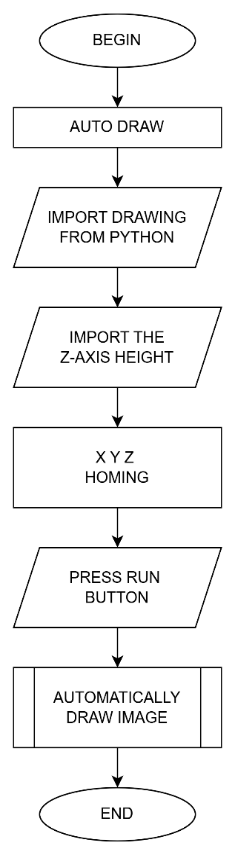
The algorithm flowchart of the model is illustrated in
Fig. 1. The system operates through a closed-loop workflow, initiated by the acquisition of input image data. In this phase, specialized image processing algorithms perform analysis, feature extraction, and surface digitization to transform the raw image into a set of spatial coordinates (X, Y) and corresponding control parameters.
Upon completion of data processing, the generated trajectory (path planning) is transmitted to the central PLC. During the execution phase, the controller actuates drive axes to guide the engraving head along a predefined trajectory. Simultaneously, the pulsed laser source is triggered in synchronization with the traverse speed to scan and interconnect the pixels. This process proceeds continuously and precisely until the image is fully reproduced on the material surface.
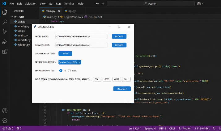
At mode AUTO RUN, the system functions in a sequential manner:
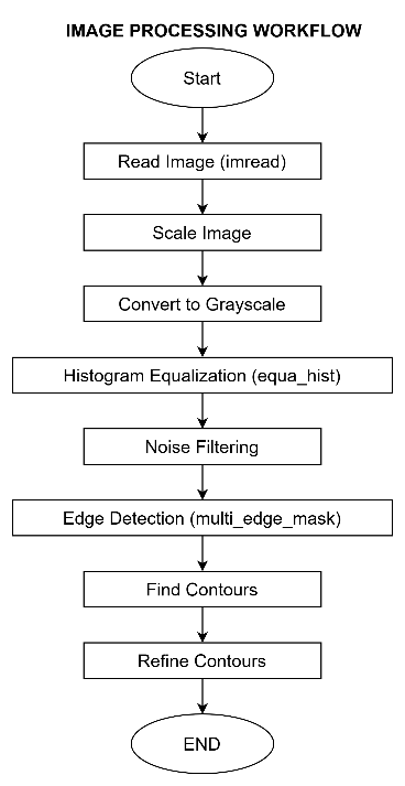
Following the digital image processing pipeline depicted in Fig. 3.
This is a mandatory initial step. Computers do not perceive images as humans do; they require the conversion of data from file formats (e.g., .jpg, .png) into a numerical matrix (pixels) to perform arithmetic operations.
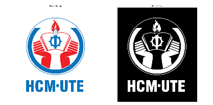
Digital image processing yielded results shown in Fig. 4.
System development workflow proceeded from conceptual design and 3D CAD modeling to component selection, electrical circuit design, mechanical assembly, and software programming.
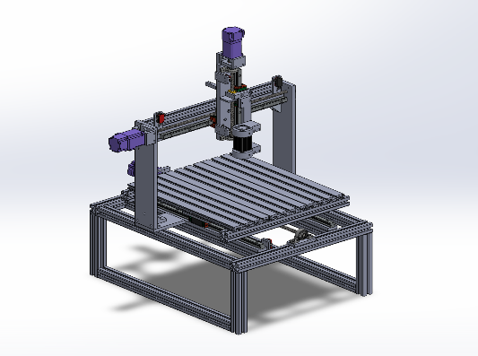
Upon completing the design in SolidWorks, we obtained a machine model as shown in Fig. 5.
The proposed system is a 3-axis Cartesian robot designed using SolidWorks. The mechanical structure utilizes aluminum extrusion profiles for the frame, ensuring rigidity and ease of assembly.
The control system is built around a PLC combined with necessary expansion modules for I/O management. Precision motion is achieved using servo motors, while the end-effector is equipped with a high-power laser module for processing.
The selection of the Q03UDE PLC is justified by its ability to perform multi-axis interpolation and its Ethernet connectivity for seamless system integration.
Reasons for choosing the QD75MH4 Module:
Reasons for selecting HF-KP13 (100W, 0.32Nm):
The connection diagram was designed in Fig. 6 to ensure the system operates in accordance with the algorithm flowchart.
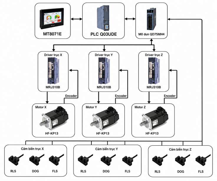
Control system for the 3-axis Cartesian robot is designed based on a hierarchical architecture, utilizing industrial-grade components from Mitsubishi Electric to ensure high precision and reliability. The system configuration is illustrated in
Fig. 7 and comprises three main levels:
To ensure operational safety and precise calibration, the system integrates a set of digital sensors for each axis (X, Y, Z). These signals are fed directly into the motion controller:
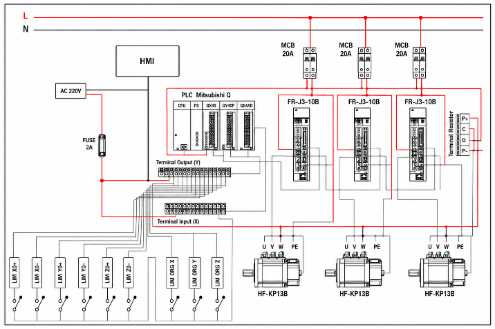
The wiring schematic was developed from the connection diagram, as illustrated in Fig. 7. Based on the connection architecture, a detailed electrical wiring diagram was developed for the system components. To ensure operational reliability, a 20 A Miniature Circuit Breaker (MCB) is dedicated to each axis (X, Y, and Z) to provide independent protection. This isolation strategy ensures that a fault occurring in a single axis does not trigger a system-wide shutdown, thereby facilitating efficient fault diagnosis and maintenance.
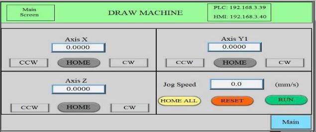
The HMI interface is illustrated in Fig. 8 below.
Interface provides dedicated control blocks for Axis X, Axis Y1, and Axis Z. Each block features a high-precision numerical display (four decimal places) for real-time position monitoring. Operators can manually manipulate each axis using the CW (Clockwise) and CCW (Counter-Clockwise) buttons for jogging, or initiate a homing sequence using the HOME button.
The bottom-right quadrant contains global operational parameters. This includes a field for setting the Jog Speed (in mm/s) and essential command buttons: HOME ALL for simultaneous homing of all axes, RESET for error clearance, and RUN to initiate the automatic operation cycle.
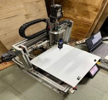
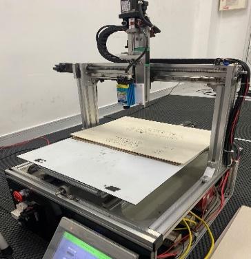
Upon completion of the mechanical fabrication, the assembled prototype is shown in Fig. 9 and Fig. 10.
The experimental model of the Cartesian laser robot has been successfully fabricated and integrated, demonstrating a high level of industrial standardization.
In essence: The fabricated prototype meets the design requirements for rigidity, precision, and operational safety, serving as a valid platform for further research into laser
engraving algorithms and automated manufacturing applications.
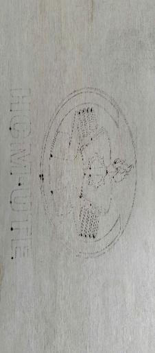
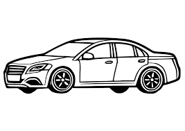
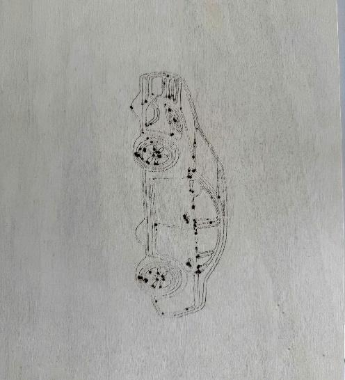
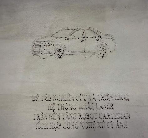
The experimental results, showing the transition from the original input image to the final engraving on the wooden workpiece, are presented in Fig. 11 to Fig. 13.
Upon comparing the original source files with the laser-engraved specimens on wood, the following observations regarding the system's performance were established:
Conclusion: The fabricated Cartesian robot prototype successfully meets the design criteria for precision laser machining. The combination of industrial servo control and rigid mechanical guidance ensures high repeatability and stable operation for complex graphical engravings.
This study successfully designed, fabricated, and experimentally evaluated a 3-axis Cartesian robot for laser engraving, distinguished by an industrial control system (Mitsubishi Q-Series PLC, MR-J3 Servo) combined with a lead screw transmission mechanism to ensure high reliability and sharp engraving quality on wood. Although the system achieved superior precision and rigidity compared to microcontroller-based solutions, the use of industrial components and lead screws resulted in limitations regarding high investment costs, low raster engraving speeds, limited diode laser power for metals or acrylics, and frequent maintenance requirements due to dust accumulation. To address these drawbacks, future work will focus on integrating a Computer Vision system for automatic workpiece localization and optimizing the laser power control algorithm to enhance product uniformity. Additionally, an automatic feeding system will be developed to fully automate the production process.
Thai-Duong Hoang, A Study of a Laser Engraving System Based on a Cartesian Robot with Image Processing