(1)
Journal of Fuzzy Systems and Control, Vol. 4, No 1, 2026 |
An Enhanced PID-Based Motion Control Framework for Autonomous Line-Following Robot
Nguyen-Thanh-Loc Tran 1, Viet-Tien-Dung Bui 2,*, Hong-Nho Bui 3, Hoang-Nguyen Nguyen 4, Thi-Ngoc-Thao Nguyen 5, Thanh-Sang Nguyen 6, Hung-Ky Nguyen 7, Huynh-Duc-Anh Nguyen 8, Thanh-Binh Phan 9, Hoang-Sang Luong 10,
Le-Minh-Tan Nguyen 11, Vo-Minh-Khoa Tran 12, Tien-Dat Nguyen 13, Huynh-Khanh-Nam Pham 14, Duc-Dat Nguyen 15,
The-Nhan Nguyen 16
1, 2, 3, 4, 5, 6, 7, 8, 9, 10, 11, 12, 13, 14, 15, 16 Ho Chi Minh City University of Technology and Engineering (HCM-UTE),
Ho Chi Minh City (HCMC), Vietnam
Email: 1 23151277@student.hcmute.edu.vn, 2 23151228@student.hcmute.edu.vn, 3 21161345@student.hcmute.edu.vn,
4 22161160@student.hcmute.edu.vn, 5 thaontnt@hcmute.edu.vn, 6 22142212@student.hcmute.edu.vn,
7 19151010@student.hcmute.edu.vn, 8 22151005@student.hcmute.edu.vn, 9 22151009@student.hcmute.edu.vn,
10 22142211@student.hcmute.edu.vn, 11 22151038@student.hcmute.edu.vn, 12 22151025@student.hcmute.edu.vn,
13 19151048@student.hcmute.edu.vn, 14 22142171@student.hcmute.edu.vn, 15 21142514@student.hcmute.edu.vn,
16 22142181@student.hcmute.edu.vn
*Corresponding Author
Abstract—PID controller is widely used in automatic control systems because it is simple, reliable, and easy to apply. It is especially suitable for mobile robots, such as line-following robots. The main contribution of this work is an experimental method to tune PID parameters. Instead of using complex algorithms, the parameters are adjusted and tested directly on a real robot. This makes the method easier to apply, especially for low-cost and educational systems. Experiments were conducted to evaluate how PID parameters (Kp, Ki, and Kd) affect the robot’s performance. The robot was tested on different paths, including straight lines, curves, and 90-degree turns. The results show that the optimal parameters are Kp = 65, Ki = 0.1, and Kd = 13. With these values, the robot moves smoothly, responds quickly, and follows the path accurately.
Keywords—PID Control; Line-Following Control; ESP; Line-Following Robot; Low-Cost and Educational Robot
The Proportional–Integral–Derivative (PID) controller is one of the most widely used control strategies in modern automatic control systems due to its simplicity, reliability, and strong performance across a broad range of
applications [1]. It has been successfully applied in industrial manufacturing processes [2], autonomous robotics [3], healthcare systems [4], vehicle guidance and stabilization [5], and other dynamic control tasks [6]. A PID controller operates through three key components: the proportional term, which responds to the current error; the integral term, which eliminates accumulated steady-state error; and the derivative term, which predicts future behavior by evaluating the rate of change of the error [7]. Owing to this structure, PID remains an essential solution for achieving stability, fast response, and accuracy in control systems.
Line-following robots represent one of the most fundamental and widely studied platforms in mobile robotics research. These robots typically rely on infrared sensors to detect the contrast between a predefined path and the surrounding surface, allowing them to autonomously follow a trajectory. Due to their relatively simple mechanical structure and low implementation cost, line-following robots are widely used in robotics education, prototype development, and experimental validation of control algorithms [8], [9].
In recent years, several advanced control approaches have been proposed to improve the performance of mobile robots. Techniques such as intelligent hybrid techniques [10], fuzzy logic combined with genetic algorithms [11], and adaptive robust control [12] have been applied to enhance trajectory tracking and motion stability. In addition, several studies have attempted to optimize PID parameters using advanced computational methods such as immune algorithms [13], MATLAB-based optimization [14], [15], fuzzy inference systems [16], [17], and particle swarm optimization [18]. These approaches can improve control accuracy and adaptability under certain conditions.
However, many of these advanced methods require complex mathematical modeling, high computational resources, or simulation-based optimization procedures. Such requirements may limit their practical applicability, particularly for low-cost robotic platforms or educational environments where simplicity, real-time implementation, and hardware constraints are important considerations. Furthermore, line-following robots operating in real environments are often affected by sensor noise, variations in ambient lighting, and nonlinear motor responses, which can degrade control performance [19], [20].
Despite the large number of studies on PID and intelligent control techniques, there remains a lack of practical research focusing on systematic experimental PID tuning strategies validated directly on real robotic platforms, particularly for low-cost mobile robots used in educational and experimental environments. Therefore, identifying a simple yet effective PID tuning approach that can be easily implemented and experimentally validated remains an important challenge in robotic motion control.
To address this issue, this study proposes a practical implementation of a discrete PID controller for a line-following mobile robot based on the ESP32 microcontroller. Instead of relying on complex optimization algorithms or intelligent hybrid controllers, this work focuses on a systematic experimental PID tuning methodology with real-time validation on a physical robotic platform. This approach emphasizes practical implementation, simplicity, and suitability for low-cost robotic systems.
The primary contributions of this work are as follows:
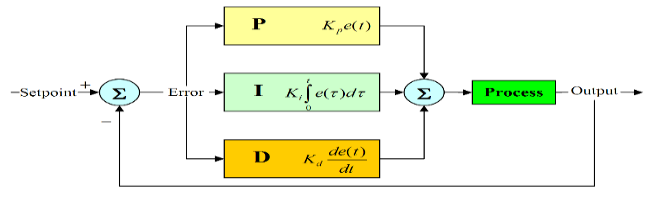
Fig. 1 a PID controller (Proportional–Integral–Derivative) is a feedback control technique widely used in automatic control systems. It continuously calculates an error value e(t) as the difference between the desired setpoint (SP) and the measured process variable (PV). The controller output u(t) is determined by combining three terms: proportional (P), integral (I), and derivative (D), as expressed in (1) [21]:
| (1) |
Where Kp – proportional gain, Ki – integral gain,
Kd – derivative gain, e(t)=SP−PV(t) – control error.
Each term of the PID controller contributes differently to the system response:
The combined effect of the P, I, and D components enables the PID controller to achieve fast response, reduced steady-state error, and stable control performance.
The line-following robot uses five infrared sensors (TCRT5000) labeled s1 s5 to detect the black line on a white surface. Each sensor outputs logic ‘0’ when detecting the line and ‘1’ otherwise. The combination of sensor readings indicates the robot’s lateral deviation from the path, as shown in Table 1.
Before conducting the experiments, the infrared sensors were calibrated to ensure reliable detection under the experimental lighting conditions. The reflected signals from both the black line and the white background were measured, and the threshold levels of the TCRT5000 modules were adjusted accordingly. Additionally, the sensors were mounted at a fixed distance from the ground to maintain stable readings and reduce measurement noise.
Sensor Value | Position of Robot |
00100 | Center |
10000 | Far right |
00001 | Far left |
Based on the sensor pattern, an error value (E) is assigned from –5 to +5, representing the deviation level. The microcontroller calculates the correction signal using the discrete PID equation:
| (2) |
Where T is the sampling period in this implementation, the PID controller is executed with a sampling period of T = 10 ms, which provides a balance between control responsiveness and the computational capability of the ESP32 microcontroller.
The output u(k) determines the PWM duty cycles applied to the left and right motors via the H-bridge driver (L298N). When the robot drifts left, the right motor speed increases and the left motor speed decreases, and vice versa. This closed-loop correction ensures the robot continuously follows the line smoothly and accurately.
Pulse Width Modulation (PWM) is used to control the average voltage supplied to the DC motors. By varying the duty cycle of a constant-frequency square wave, the motor speed can be adjusted [23], [24]:
Increasing the duty cycle → higher average voltage → higher speed, Decreasing the duty cycle → lower voltage → lower speed.
PWM offers high efficiency, low power loss, and easy implementation using microcontrollers, making it a suitable technique for motor speed control in mobile robots.
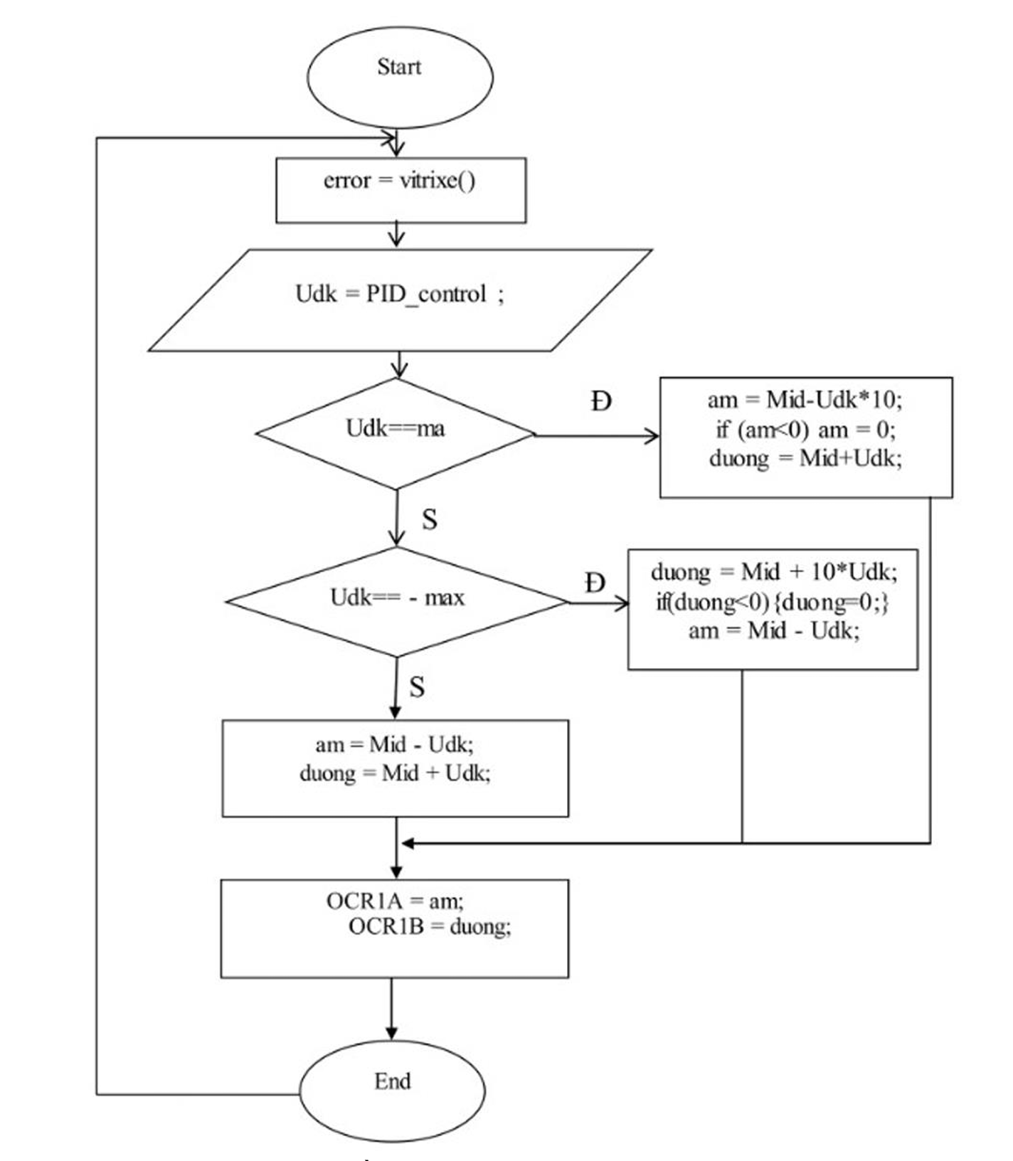
The motor speed control based on the PID output is illustrated in the flowchart shown in Fig. 2. First, the microcontroller reads the line deviation through the function vitrixe(), which returns the error value E. The discrete PID controller then computes the control signal U(k) using the current and past error values.
To ensure stable operation, the control signal is constrained within a predefined range [−max,+max]. When the PID output reaches its saturation limits, specific correction rules are applied to maximize the robot's turning capability. Under normal operation, the left and right motor commands are obtained by adding and subtracting the PID output from the nominal reference value (Mid).
Finally, the calculated values are written to the PWM registers (OCR1A and OCR1B), which determine the duty cycles for the left and right motors. This closed-loop feedback mechanism allows the robot to continuously adjust motor speeds, enabling smooth and accurate line-following performance under varying conditions.
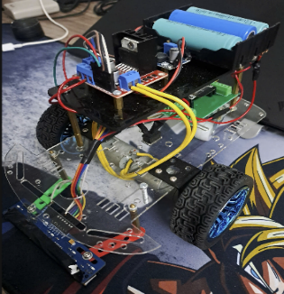
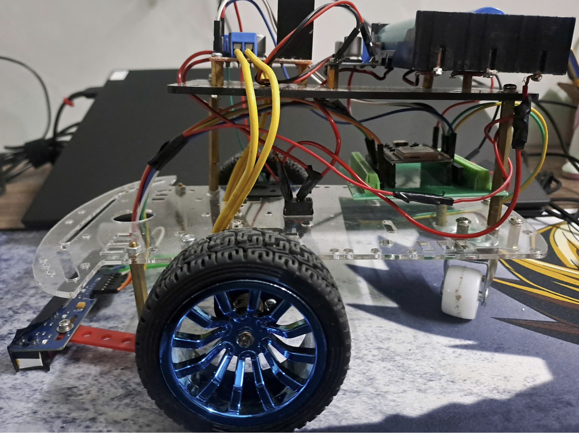
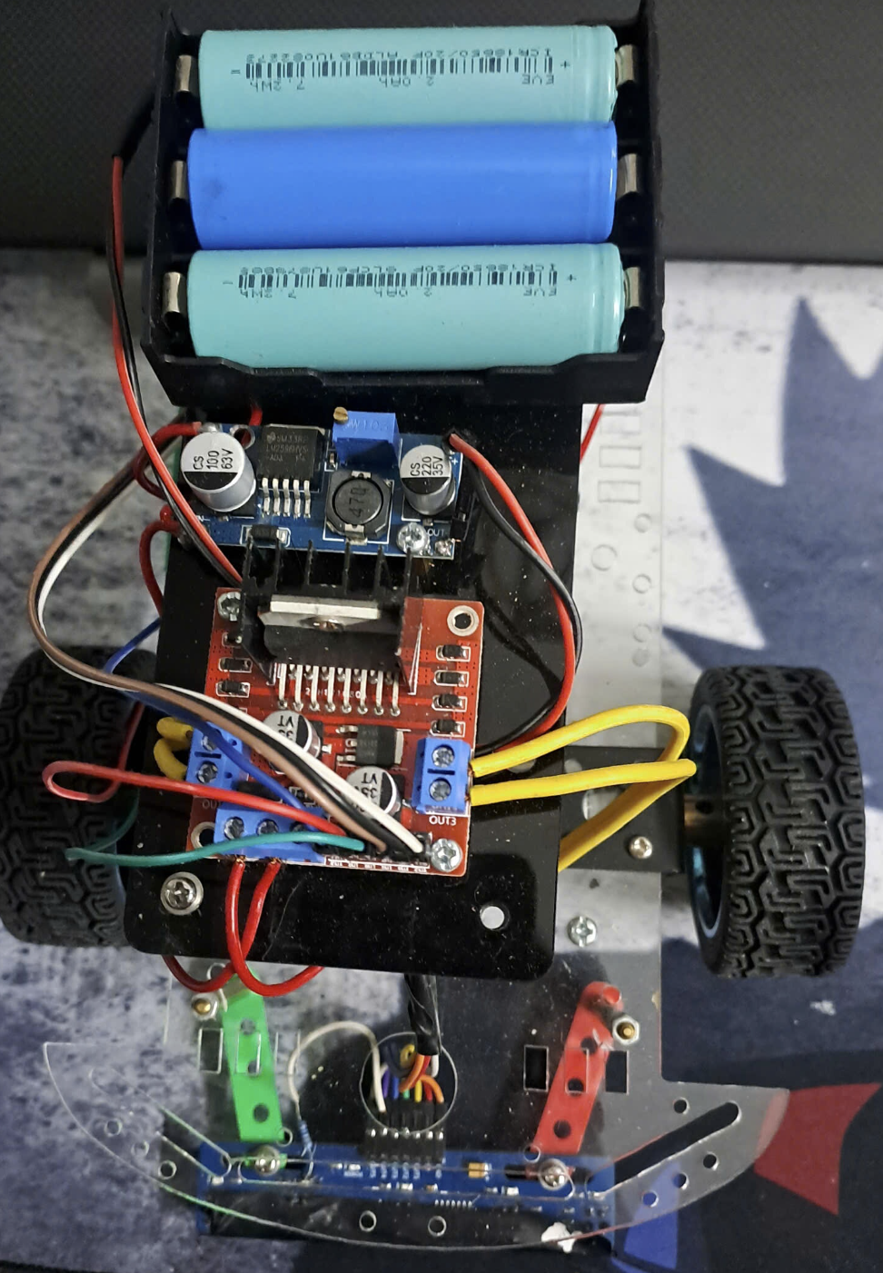
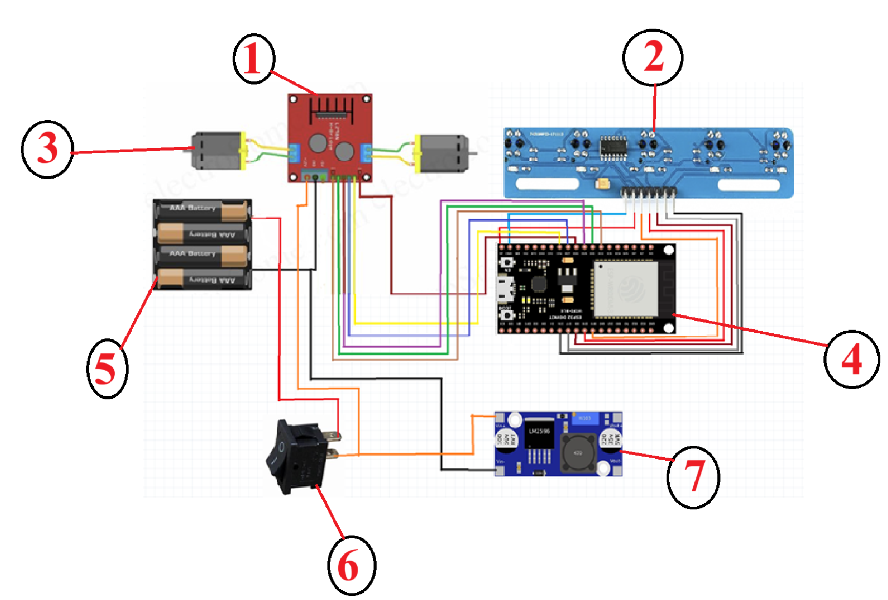
This project implements a line-following robot that uses infrared sensors (TCRT5000) to detect and track a line on the floor. The sensor data are processed by an ESP32 microcontroller, which controls two DC motors through the L298N motor driver module [25]. A discrete PID controller is applied to balance the motor speeds, allowing the robot to follow the path smoothly and maintain stability during turns or sudden direction changes.
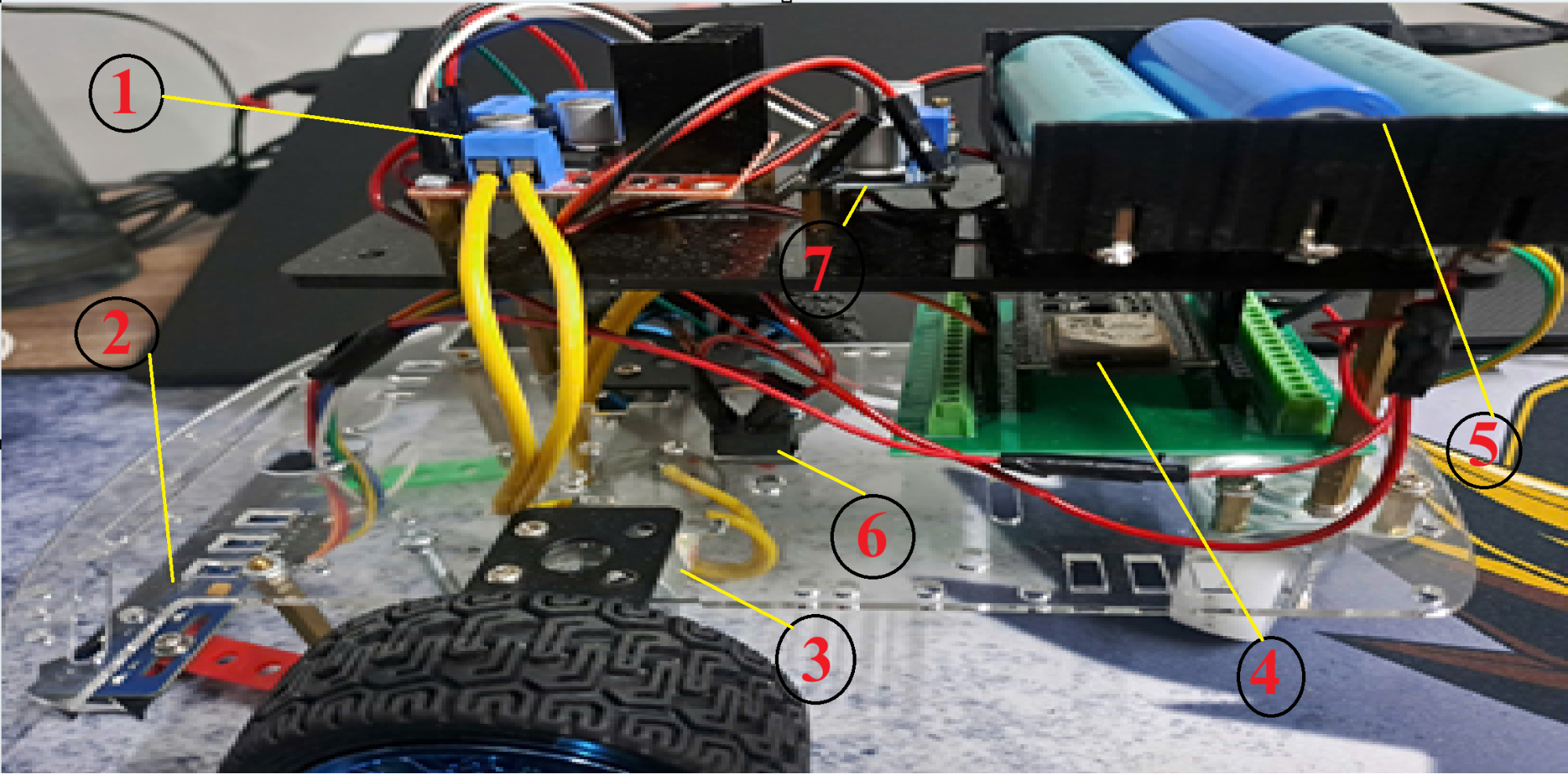
Fig. 3 to Fig. 5 present different views of the experimental robot platform, including the sensor arrangement and motor driver configuration.
From Table 2, components are as follows:
When the robot deviates from the line, the PID controller increases the speed of the motor on the opposite side, steering the robot back to the correct path. This enables smooth and accurate line tracking even at higher speeds [30].
Station | Unit |
1 | L298N |
2 | Line sensor |
3 | DC motor |
4 | ESP32 |
5 | Battery |
6 | Switch |
7 | LM2596 |
The infrared sensors continuously read reflected light values from the surface. When the robot deviates from the line, the ESP32 calculates the positional error and applies the discrete PID algorithm to modify the PWM signals of both motors [31]. This feedback mechanism allows the robot to quickly return to the correct path, achieving smoother and more stable motion compared to traditional control methods [32].
Initially, we set the speed to 120/255, but it was too fast, making it difficult to tune the PID parameters. Therefore, we reduced the speed to 50/255, which made it easier to find suitable parameter values. The results of our experiments are presented in Table 3 and Table 4.
Parameter | Kp | Ki | Kd | Result |
PID-1 | 65 | 0.1 | 13 | |
PID-2 | 66 | 0.1 | 13 | |
PID-3 | 67 | 0.1 | 13 | |
PID-4 | 65 | 0.2 | 13 | |
PID-5 | 65 | 0.1 | 14 | |
PID-6 | 65 | 0.1 | 12 |
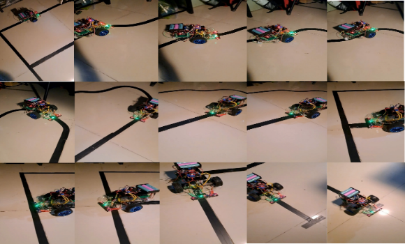
The experimental tests were conducted on a track consisting of multiple segments, including straight paths, 90° turns, and curved sections. The corresponding output responses of the robot were observed for each trajectory condition.
To provide a clearer evaluation of the controller's performance, several basic quantitative indicators were considered during the experiments. These include the tracking error, which represents the deviation of the robot from the reference line, the maximum lateral deviation, and the settling behavior, which describes how quickly the robot returns to the correct path after a disturbance.
At first, a very small value of Kp was selected and gradually increased while observing the behavior of the vehicle until it was able to follow the line steadily. The main evaluation criteria during this stage were the tracking sensitivity and the oscillation level of the robot.
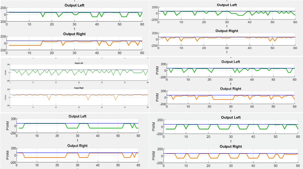
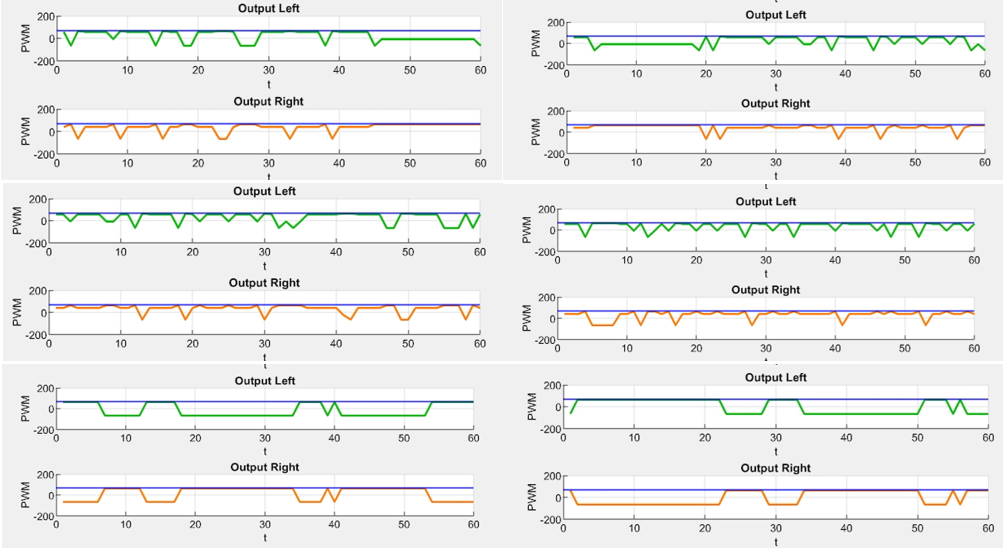
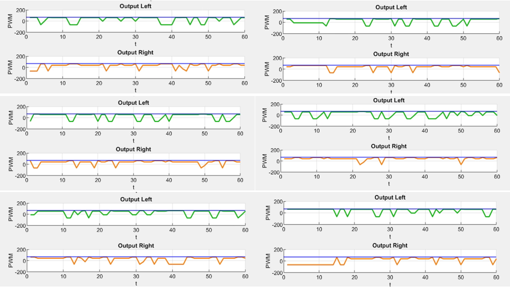
Fig. 8 shows the response of the robot when the PID parameters were initially set to Kp = 65, Ki = 0.1, and Kd = 13. The motor output indicates that the vehicle maintained relatively stable motion across different track sections.
Fig. 9 and Fig. 10 illustrate the system response when the proportional gain was further increased while keeping Ki and Kd constant. After adjusting Kp while keeping Ki and Kd constant at 0.1 and 13, respectively, we observed noticeable changes in the line-following performance of the vehicle. When Kp = 65 as shown in Fig. 9, the motor output indicates that the vehicle moved smoothly and maintained a stable trajectory along the line, demonstrating satisfactory performance.
However, when Kp was slightly increased to 66, the vehicle began to exhibit mild oscillations and a slightly slower response, as indicated by the motor output waveforms in
Fig. 10. Although the motion was less smooth, the vehicle was still able to traverse the entire path without losing the line.
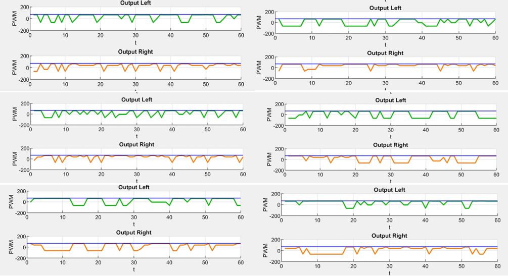
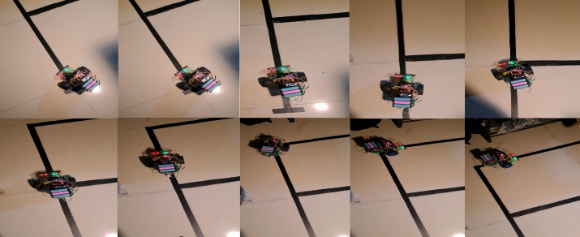
As Kp was further increased to 67, the vehicle’s performance deteriorated significantly. It deviated from the intended trajectory, particularly at 90° right turns where it lost the line and rotated repeatedly while attempting to reacquire it. After some time, the vehicle managed to find the line again, but with considerable delay. In curved sections, slight deviations were also observed.
These results indicate that an excessive increase in Kp causes the system to become unstable, reducing both tracking accuracy and smoothness. Therefore, Kp = 65 was selected as the optimal value for subsequent tuning of Ki.
In the second step, the controller was operated as a PID controller. The integral gain Ki is responsible for eliminating the steady-state error, which is the remaining error when only Kp is used, and the vehicle cannot perfectly follow the line. It accumulates the error over time, helping the vehicle maintain a more stable trajectory on straight sections. However, if Ki is too large, the vehicle may experience overshoot or oscillation due to excessive error accumulation. The Ki value was adjusted starting from a small value and gradually increased until the system began to oscillate if increased further. The Kp and Ki values were then retained for the next step.
We maintained constant values of Kp = 65 and Kd = 13 while varying the integral gain, Ki. As illustrated in Fig. 8, increasing Ki resulted in system instability, characterized by visible vibrations and a sluggish response. It appears that the stability threshold was exceeded at Ki = 0.1, as even a minor increase to 0.2 caused significant performance deterioration—the vehicle lost its smooth motion and even deviated from the trajectory, as clearly evidenced by the erratic motor output waveforms shown in Fig. 11. We attribute this phenomenon to excessive oscillations generating substantial inertia, which caused the vehicle to drift off the track. Consequently, we decided to retain Kp = 65 and Ki = 0.1 for the subsequent adjustment of Kd.
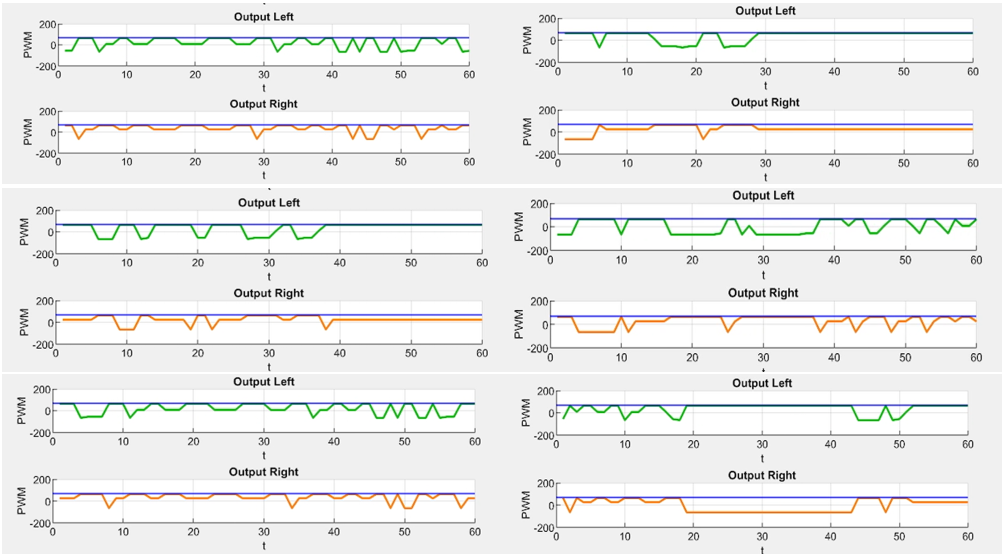
After adjusting Ki, we identified suitable parameters that allowed the system to stabilize with a small error. We then proceeded to investigate Kd to complete the controller. The adjustment process was carried out in the same manner as the previous steps, ultimately resulting in the optimal parameter set for the system.
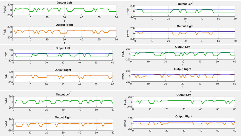
We maintain constant values of Kp = 65 and Ki = 0.1 while varying the derivative gain, Kd. Increasing Kd to 14 results in moderate oscillations, as illustrated in Fig. 12. Although the vehicle occasionally deviated from the trajectory, it successfully reacquired the line; however, the overall stability was inferior compared to the Kd = 13 configuration. Conversely, decreasing Kd to 12 results in a slower system response. While the vehicle managed to complete the course despite deviations, its performance varied across different track sections. Specifically, it remained stable on 3-line sections but showed deviations followed by recovery on 2-line sections. Notably, performance at 90° turns was inconsistent: the robot occasionally tracked well but at other times failed to detect the turn, leading to overshoot, as clearly depicted in Fig. 13.
Further experiments were conducted with various combinations of parameters, and based on the experimental results in Fig. 14 is the trajectory, and Fig. 15 is the optimal result graph with the optimal parameters determined as Kp = 65, Ki = 0.1 and Kd = 13. With these values, the vehicle moves stably in a straight line, moves smoothly without being sluggish, turns effectively on curves, and handles 90° corners well. However, on 2-line straights, the vehicle sometimes oscillates slightly to the left or right but quickly corrects itself and continues straight. On 3-line straights, the vehicle moves completely smoothly and straight, showing excellent performance
Case | Kp | Ki | Kd | Tracking Error | Max Deviation | System Behavior |
PID-1 | 65 | 0.1 | 13 | Low | Small | Stable motion |
PID-2 | 66 | 0.1 | 13 | Medium | Moderate | Slight oscillation |
PID-3 | 67 | 0.1 | 13 | High | Large | Unstable |
PID-4 | 65 | 0.2 | 13 | High | Large | Strong oscillation |
PID-5 | 65 | 0.1 | 14 | Medium | Moderate | Moderate oscillation |
PID-6 | 65 | 0.1 | 12 | Medium | Moderate | Slow response |
This study presented the design and implementation of a PID-based line-following robot using an ESP32 microcontroller and infrared sensors. The objective was to investigate the influence of PID parameters on the tracking performance and stability of the robot.
Through systematic experimental tuning, the optimal controller parameters were identified as Kp = 65, Ki = 0.1, and Kd = 13. With this configuration, the robot demonstrated stable motion, smooth trajectory tracking, and reliable performance when navigating straight paths, curved segments, and 90° turns.
The main contribution of this work lies in the systematic experimental tuning approach applied to a low-cost robotic platform. Unlike many existing studies that rely on complex optimization or intelligent control methods, the proposed method demonstrates that carefully tuned classical PID control can still achieve reliable line-following performance using simple hardware components. This approach provides a practical and cost-effective solution for mobile robotics and educational applications.
In addition to its practical relevance, the developed experimental platform can serve as a useful educational tool for studying feedback control, embedded systems, and robotic motion control.
Future work may focus on improving the system performance through adaptive PID tuning, fuzzy control strategies, or machine learning–based optimization methods. Further experiments on more complex track configurations and higher operating speeds could also be conducted to evaluate the robustness of the proposed approach.
This research was funded by Ho Chi Minh City University of Technology and Engineering, Vietnam, under grant No. SV2026-216. We want to give thanks to the PhD. Van-Dong-Hai Nguyen (HCM-UTE) due to his supervision for this study. Link of operation of the model is: https://youtube.com/shorts/dEiUP1Y-SKw?feature=share.
Nguyen-Thanh-Loc Tran, An Enhanced PID-Based Motion Control Framework for Autonomous Line-Following Robot