Journal of Fuzzy Systems and Control, Vol. 4, No 2, 2026 |
Software-Based Digital PID Control for a Single-Tank Water Level System
Quoc-Toan Nguyen 1, Hai-Duong Nguyen 2, Anh-Tuan Nguyen 3, Tan-Khang Nguyen 4, Quoc-Hung Nguyen 5,
Phuc-Khanh Dang 6, Truong-Viet Nguyen 7, Quoc-Bao Nguyen 8, Xuan-Cuong Le 9, Van-Hai Nguyen 10,
Huynh-The-Hung Nguyen 11, Bao-Trung Mai 12, Phong-Luu Nguyen 13,*, That-Ngoc-Hai Ton 14, Tan-Loc Pham 15,
Minh-Tan Nguyen 16
1, 2, 3, 4, 5, 6, 7, 8, 9, 10, 11, 12, 13, 14, 15, 16 Ho Chi Minh City University of Technology and Engineering (HCM-UTE),
Ho Chi Minh City (HCMC), Vietnam
Email: 1 23151321@student.hcmute.edu.vn, 2 23151230@student.hcmute.edu.vn, 3 22142246@student.hcmute.edu.vn,
4 21161325@tudent.hcmute.edu.vn, 5 22142137@student.hcmute.edu.vn, 6 19142177@student.hcmute.edu.vn,
7 22142255@student.hcmute.edu.vn, 8 21142072@student.hcmute.edu.vn, 9 21142501@student.hcmute.edu.vn,
10 22142115@student.hcmute.edu.vn, 11 22142124@student.hcmute.edu.vn, 12 20142435@student.hcmute.edu.vn,
13 luunp@hcmute.edu.vn, 14 20161186@student.hcmute.edu.vn, 15 21161064@student.hcmute.edu.vn,
16 21161359@student.hcmute.edu.vn
*Corresponding Author
Abstract—The single tank system is one of the fundamental systems in the field of automatic control and is a suitable choice for implementing system control using a PID controller. Nowadays, the single tank system is widely used in laboratories for conducting experiments related to PID control. Due to its low cost, easily available components, simple construction, and ease of observation, the single tank system is an appropriate model for research in automatic control systems. The primary control method applied to the single tank system is the digital PID control method, also known as discrete PID control, the PID parameters (Kp, Kd, Ki) are selected by the trial-and-error method. Therefore, this paper investigates the variation of transient responses when changing the parameters of the PID controller in order to evaluate the model during laboratory implementation. The main objective of this paper is to design a discrete PID controller through simulation and to experimentally investigate its performance on a real single tank system. Experimental results show that the system operates stably, and the pump speed can be adjusted by changing the parameters of the PID controller. The overshoot starts at over 0.2%, the steady-state error is about 0.02 cm, and the settling time is approximately 4.5 to 5 seconds.
Keywords—PID Control; Discrete PID; Digital PID; Single Tank System
Water level control in tank systems is a fundamental problem in the field of automatic control and is widely encountered in industrial applications such as water treatment, chemical processing, and irrigation systems. Due to its simple structure and well-defined physical behavior, the single-tank system is commonly used as a benchmark model for studying control strategies in both research and educational laboratories. However, the inherent nonlinear dynamics of the system, mainly caused by the nonlinear relationship between the outlet flow rate and the liquid height, make accurate water level regulation a challenging control problem.
Various control approaches have been proposed to address the nonlinear characteristics of tank systems. Intelligent control methods, particularly fuzzy logic-based techniques, have been widely investigated. For example, Imaduddin [1] designed a fuzzy logic controller for water level regulation and demonstrated its effectiveness in handling system nonlinearities. Similarly, Saad et al. [2] proposed a fuzzy PID controller for coupled tank systems, achieving improved robustness and stability. In addition to intelligent methods, optimization-based approaches have also been explored. Qu et al. [3] applied optimization algorithms such as particle swarm optimization (PSO) and genetic algorithms (GA) to enhance PID controller performance in complex systems. Furthermore, Das et al. [4] introduced an improved discrete PID controller based on LQR optimization, resulting in enhanced system stability and transient performance.
Besides these advanced control strategies, conventional PID controllers remain one of the most widely used control techniques in industrial applications due to their simple structure, reliability, and ease of implementation.
Rahmani et al. [5] presented a PID-based water level control system and showed that the controller can maintain stable operation with acceptable transient response characteristics. Bhookya et al. [6] investigated the implementation of a PID controller for liquid level systems using optimization techniques combined with IoT applications. More recent research has also explored hybrid approaches to improve control performance. For instance, Ghazali et al. [7] proposed a hybrid sliding mode control with gain-scheduled PID for water tank systems to enhance disturbance rejection capability. A comparative study between PI and PID controllers for coupled tank systems and concluded that PID controllers generally provide better transient performance [8].
Despite the advantages of advanced and intelligent control methods, conventional PID controllers remain the most widely used control strategy in industrial applications due to their simple structure, reliability, and ease of implementation. Several studies have demonstrated the effectiveness of PID control in liquid level systems. For instance, Hossain et al. [9] showed that properly tuned PID controllers can achieve stable and accurate water level regulation. Similarly, Tokhi and Hossain [11] utilized system identification techniques to improve PID performance in liquid level control systems. In addition, Bhookya et al. [6] investigated the integration of PID control with IoT technologies, highlighting the feasibility of real-time monitoring and control.
Recent research has also focused on implementing control algorithms on embedded platforms and integrating them with modern communication technologies. Kumar et al. [10] and Menaka and Shrinithi [12] developed IoT-based water level monitoring systems, enabling real-time data acquisition and remote operation. Moreover, Efendi and Candra implemented an Arduino-based PID controller using ultrasonic sensors, demonstrating the practicality of low-cost embedded control systems. Advanced hybrid control strategies have also been proposed to further improve system performance. For example, Ghazali et al. [11] developed a hybrid sliding mode control combined with gain scheduling PID to enhance disturbance rejection capability, while Yesil and Sahin [8] implemented a real-time microcontroller-based control system with improved performance. In addition, classical PID tuning methods such as Ziegler–Nichols [14] and Cohen–Coon [15] remain widely used in practice due to their simplicity and ease of application, especially in laboratory-scale systems.
Although these advanced and hybrid approaches can provide improved control performance, they often require complex mathematical modeling, high computational cost, or sophisticated tuning procedures. This limits their applicability in low-cost laboratory environments, where simplicity, transparency, and ease of implementation are essential for educational purposes.
Therefore, this paper focuses on the design and experimental implementation of a digital PID controller for water level control in a single-tank system using a low-cost Arduino-based platform. The main contributions of this study are summarized as follows. First, a nonlinear mathematical model of the single-tank system is developed and implemented in MATLAB/Simulink for simulation analysis. Second, a discrete digital PID controller is designed and implemented on an Arduino Mega 2560 microcontroller. Third, the controller performance is experimentally validated using a real laboratory setup. Finally, the effects of PID parameters on transient response characteristics, including overshoot, settling time, and steady-state error, are systematically investigated.
The single tank system is a discrete-time control system used for water storage and supply. The system consists of several functional blocks, as illustrated in Fig. 1. The control block is an Arduino microcontroller, which is directly connected to a computer. This block is responsible for storing commands and control algorithms, performing computations, and generating control signals.
The water pump acts as the actuator that creates water circulation within the system. The water tank serves as both the storage and supply unit for water. An ultrasonic sensor is employed to measure the distance to the water surface, from which the water level is calculated. The measured water level is then fed back to the control block to perform subsequent control actions.
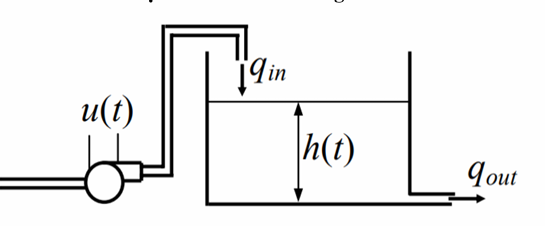
The dynamic behavior of a single tank system is described based on the mass balance principle (Fig. 2). The rate of change of the water level depends on the difference between the inlet flow rate and the outlet flow rate.
The inlet flow generated by the pump is assumed to be proportional to the control input voltage through (1):
| (1) |
where 𝑢(𝑡) is the control voltage applied to the pump and k is the pump gain coefficient. The outlet flow is determined based on Torricelli’s law through (2):
| (2) |
where: CD is discharge coefficient; a is the cross-sectional area of the outlet, and g is gravitational acceleration.
Applying the mass balance equation gives (3):
| (3) |
Substituting expressions of qin(t) and qout(t), the nonlinear differential equation of the system is obtained as in (4):
| (4) |
The cross-sectional area of the tank is defined as in (5):
| (5) |
where: is inlet flow rate;
  is the outlet flow rate;
  is the pressure;
  is the water level;
  is the maximum height of the tankA(h) is the cross sectional area of the tank;
  and
and  denote the maximum and minimum cross-sectional areas;
  is the gravitational acceleration
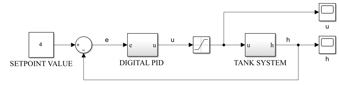
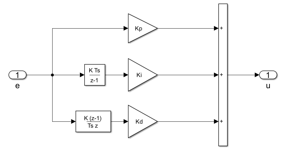
A single-tank system is simulated using MATLAB/Simulink in Fig. 3 and parameters for simulation as shown in Table 1. The internal structure of the digital PID controller is illustrated in Fig. 4. The controller consists of three main components: Proportional, integral, and derivative terms. The proportional term provides an output proportional to the current error, the integral term accumulates past errors to eliminate steady-state error, and the derivative term predicts the system behavior to improve stability. The outputs of these three components are summed to generate the final control signal.
Fig. 5 shows the internal structure of the tank system block implemented in MATLAB/Simulink. The system receives the control input u, which is processed through a nonlinear function representing the tank dynamics. The output is then integrated to obtain the water level h. This block models the nonlinear behavior of the tank system based on the mathematical (4).
Parameter | Description | Value |
hmax | Maximum water level | 15 cm |
hinit | Initial level of water | 0 cm |
Amax | Maximum cross–sectional area of tank | 234 cm2 |
Amin | Minimum cross–sectional area of tank | 234 cm2 |
k | Proportional coefficient related pump power | 300 cm3/s |
a | Outlet valve cross–sectional area | 0.5 cm2 |
g | Gravitational acceleration | 918 cm/s2 |
CD | Coefficient of Discharge | 0.6 |
PID controller parameters were determined using a trial-and-error tuning approach. Initially, proportional gain KP was increased gradually until the system exhibited a fast response with acceptable oscillations. Then, integral gain KI was introduced to eliminate steady-state error, while ensuring system stability. Finally, the derivative gain KD was adjusted to reduce overshoot and improve transient response. When the gain values of the PID controller are varied, the output response of the system also changes. For example, increasing KP increases overshoot and reduces rise time, but may introduce steady-state error. Increasing KI can significantly increase overshoot, while eliminating steady-state error. Increasing KD improves system stability and reduces overshoot. Table 2 summarizes the effects of increasing PID gains on the system response.
Increased Parameter | Effect on Rise Time | Effect on Overshoot | Effect on Settling Time | Effect on Steady-state Error |
KP | Decrease | Increase | Slight change | Decrease |
KI | Decrease | Increase significantly | Increase | Eliminate |
KD | Slight change | Decrease | Decrease | Slight change |
Fig. 6 presents simulation results of PID controller, illustrating the variations in water level when PID parameters are selected randomly (KP = 20$, KI = 0.1, KD = 0.01). The results indicate that output response exhibits an overshoot of approximately 6.25%, a settling time of about 2.5 seconds, and a zero steady-state error. In Fig. 6, the water level at the initial time (0 second) is larger than 0, that means at first, the tank had a little of water, not completely empty.
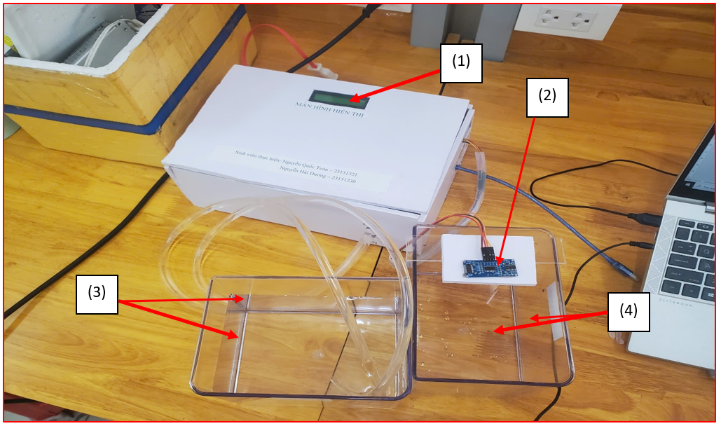
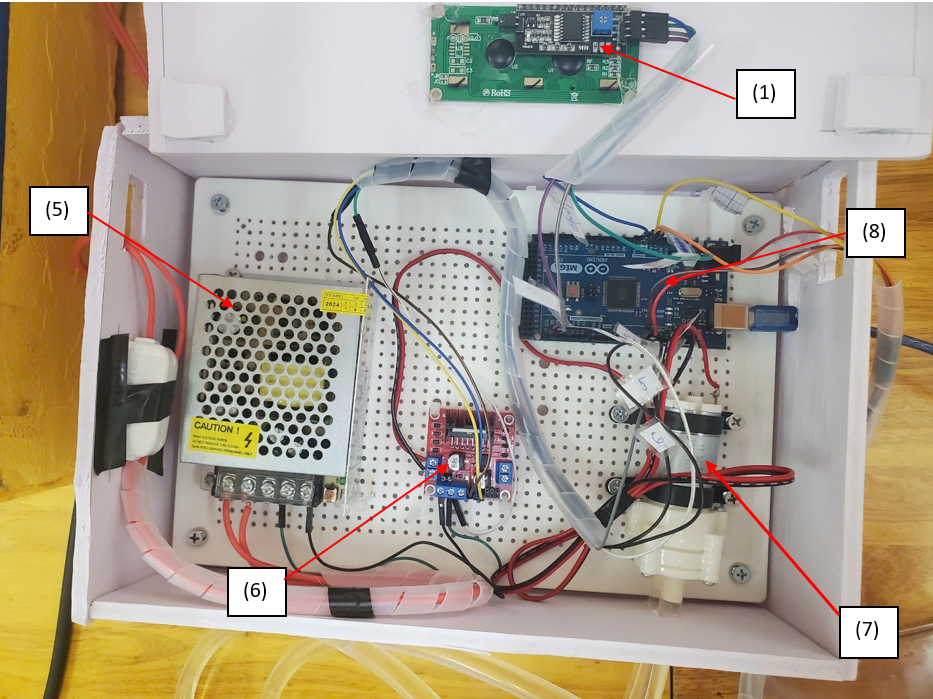
The experimental model is shown in Fig. 7. The description of components: (1): LCD display, (2): HC SR04 ultrasonic sensor, (3): Supply water tank, (4): Controlled tank, (5): 12V - 3A Switching power supply, (6): L298 H – bridge driver module, (7): 385DC water pump 12VDC, (8): Arduino Mega 2560. A flowchart illustrating a hardware system is shown in Fig. 8.
Experimental data presented in the tables and figures were collected directly from the real-time measurements of the system using the ultrasonic sensor (HC-SR04) and recorded via the Arduino Mega 2560. The data were transmitted to a computer and processed for analysis.
The response curves shown in the figures are plotted based on the recorded experimental data. The same dataset is used to compute the performance metrics presented in the corresponding tables, including overshoot, settling time, and steady-state error.
A nominal PID controller is selected with parameters KP = 40, KI = 5, and KD = 3. A sampling period is set to T = 0.05 s, and the reference water level is 4 cm.
While keeping KI and KD constant at their nominal values, the proportional gain KP is varied, and the responses of system are shown in Table 3 and Fig. 9.
KP | 40 | 50 | 60 | 70 | |
Overshoot (%) | 0.277 | 0.904 | 2.049 | 1.411 | |
Steady-state Error (cm) | 0.019 | 0.108 | 0.019 | 0.02 | |
Settling time (s) | 4.75 | 7.45 | 7.2 | 6.1 |
As KP increases, the control signal applied to the pump becomes more aggressive, resulting in a faster rise of the water level. In the actual system, this causes the pump to deliver a higher flow rate in a short time, leading to an excessive accumulation of water in the tank. Due to the inherent delay in the system, including the response time of the pump and the measurement delay of the ultrasonic sensor, the controller cannot immediately compensate for this rapid increase. As a result, the water level exceeds the reference value, producing overshoot.
Moreover, higher values of KP make the system more sensitive to measurement noise and disturbances. In the experimental setup, small fluctuations in sensor readings can lead to significant variations in the control signal, thereby contributing to oscillatory behavior. This explains why the settling time may increase when KP is too large, especially under strong oscillation conditions.
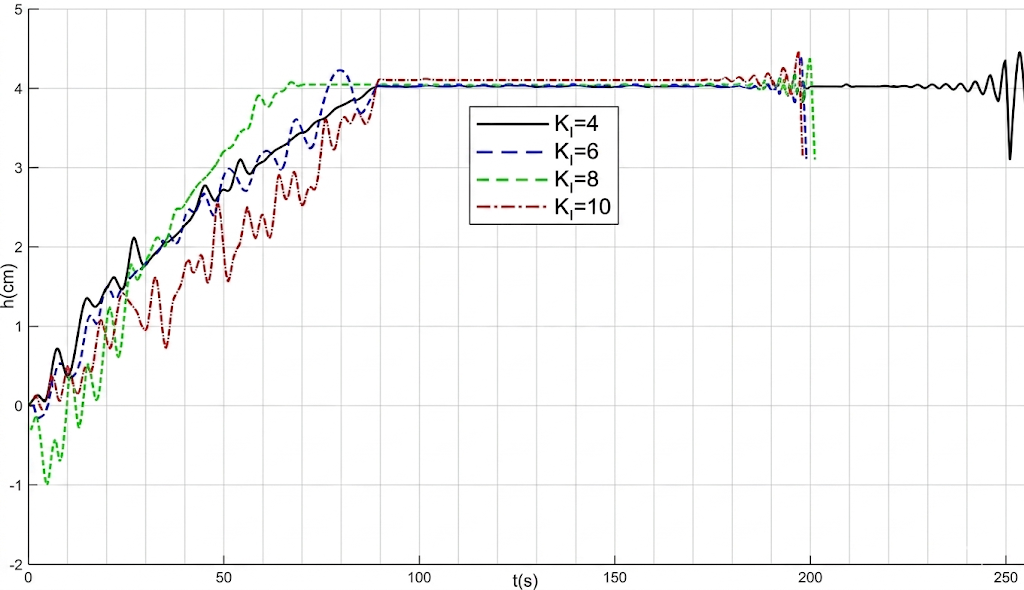
While keeping KP and KD constant at their nominal values, the proportional gain KI is varied and the response of the system is shown in Table 4 and Fig. 10.
control error over time, which results in a stronger control signal applied to the pump. In the experimental system, this causes the pump to operate more aggressively in order to eliminate the steady-state error. However, due to the inherent delay in the system, including the response time of the pump and the measurement delay of the ultrasonic sensor, the accumulated control action may become excessive. As a result, the water level can exceed the reference value, leading to increased overshoot.
KI | 5 | 6 | 7 | 8 |
Overshoot (%) | 0.277 | 1.004 | 0.782 | 4.964 |
Steady-state Error (cm) | 0.019 | 0.028 | 0.015 | 0.024 |
Settling time (s) | 4.75 | 5.5 | 5.6 | 7.15 |
As KI increases, the integral action accumulates the Moreover, the integral term continues to act based on past errors even after the system output approaches the reference value. This can cause the system to take a longer time to settle, especially when KI is large. Therefore, although increasing KI helps reduce or eliminate steady-state error, it may also degrade transient performance by increasing overshoot and settling time.
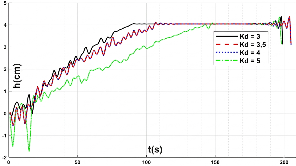
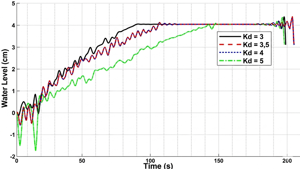
While keeping KP and KI constant at their nominal values, the proportional gain KD is varied, and the system response is shown in Fig. 11 and Table 5.
KD | 3 | 3.5 | 4 | 5 |
Overshoot (%) | 0.277 | 0.087 | 2.029 | 1.355 |
Steady-state Error (cm) | 0.019 | 0.043 | 0.033 | 0.032 |
Settling time (s) | 4.75 | 4.75 | 6.35 | 8.05 |
Derivative gain KD is responsible for predicting the future trend of the error based on its rate of change, thereby improving the damping characteristics of the system. In the experimental setup, increasing KD generally helps reduce overshoot by slowing down the system response when the water level approaches the reference value.
However, the derivative term is highly sensitive to measurement noise from the ultrasonic sensor. In practice, small fluctuations in the measured water level can produce large variations in the derivative signal, which may lead to oscillatory behavior in the control signal. This explains why, for certain values of KD, the system may exhibit increased oscillations and longer settling time. Therefore, an appropriate choice of KD is required to balance noise sensitivity and damping performance.
While keeping the PID gains Kp, KI, and KD fixed at their nominal values, the reference water level is increased from 4 cm to 5 cm. System response is shown in Fig. 12 and Table 6.
Reference Water Level (cm) | 4 | 5 |
Overshoot (%) | 0.277 | 0.639 |
Steady-state Error (cm) | 0.019 | 0.134 |
Settling time (s) | 4.75 | 5.55 |
When the reference water level is increased, the overshoot increases, the steady-state error becomes larger, and the settling time increases. This is because the system requires a longer time to reach the steady-state value as the reference level increases.
In this paper, a discrete PID controller for a water level control system has been designed and implemented on an Arduino-based platform. Both simulation and experimental results have been conducted to evaluate the system performance.
The experimental results show that the proposed controller is capable of maintaining the desired water level with acceptable performance. Specifically, the system achieves a maximum overshoot of approximately 4.964%, a settling time of about 8.05s seconds, and a steady-state error close to 0.108cm. The comparison between simulation and experimental results indicates that the mathematical model provides a reasonable approximation of the real system behavior.
However, some discrepancies between simulation and experimental results are observed due to practical factors such as system nonlinearity, time delay, and measurement noise from the ultrasonic sensor.
In future work, the control performance can be further improved by applying advanced tuning methods or intelligent control strategies such as fuzzy logic or adaptive control. Additionally, system robustness under varying operating conditions will be investigated.
A video demonstrating the experimental setup and real-time water level control of the single tank system using a digital PID controller is available at: https://www.youtube.com/watch?v=ch04KnwgwnM.
Quoc-Toan Nguyen, Software-Based Digital PID Control for a Single-Tank Water Level System