(1)

(2)
Journal of Fuzzy Systems and Control, Vol. 4, No 2, 2026 |
Conveyor Speed Control with Fuzzy-PID
Minh-Nam Phan 1, Van-Thao Nguyen 2, The-An Nguyen 3, Thi-Ngoc-Thao Nguyen 4, Thanh-Binh Nguyen 5,
Thi-Hong-Lam Le 6,*, Van-Hiep Nguyen 7, Hoang-Lam Le 8, Van-Phuc Nguyen 9, Phong-Nam Huynh 10, Vi-Cuong Hong 11, Tuan-Minh Truong 12, Kieu-Vinh Nguyen 13, Huu-Nhan Tran 14
1, 2, 3, 4, 5, 6, 7, 8, 9, 10, 11, 12, 13, 14 Faculty of Electrical and Electronics Engineering (FEEE), Ho Chi Minh City University of Technology and Engineering (HCM-UTE), Ho Chi Minh City (HCMC), Vietnam
Email: 1 22151261@student.hcmute.edu.vn, 2 22151296@student.hcmute.edu.vn, 3 22151170@student.hcmute.edu.vn,
4 thaontn@hcmute.edu.vn, 5 binhnt@hcmute.edu.vn, 6 lamlth@hcmute.edu.vn, 7 hiepnv@hcmute.edu.vn,
8 lamlh@hcmute.edu.vn, 9 23142184@student.hcmute.edu.vn, 10 22151030@student.hcmute.edu.vn,
11 22151010@student.hcmute.edu.vn, 12 21151425@student.hcmute.edu.vn, 13 22145289@student.hcmute.edu.vn,
14 20145086@student.hcmute.edu.vn
*Corresponding Author
Abstract—Conveyor belt systems are essential components in industrial automation, but controlling their speed accurately is a significant challenge. Classic PID controllers, while common, struggle to handle the inherent nonlinearities of these systems, such as varying friction and sudden load changes. The adaptive Fuzzy-PID controller, which auto-tunes its parameters, has been proposed as a superior alternative. However, most existing research is limited to software simulations, leaving a gap between theoretical performance and practical, real-world applicability. This paper addresses this gap by presenting the complete design, construction, and experimental verification of a Fuzzy-PID controller implemented on a physical conveyor belt model. The methodology includes system identification via multi-sine input to extract a baseline transfer function, followed by the deployment of the control algorithm on an embedded Arduino Nano microcontroller. Experimental results are presented and directly compared with those of a conventional PID controller to evaluate its performance. Quantitative findings confirm that the embedded Fuzzy-PID controller provides superior performance, reducing the rise time to 0.16 s (from 0.20 s) and significantly decreasing the settling time to 0.56 s (a 48.1% improvement over the PID's 1.08 s). Furthermore, the steady-state error was reduced by 36.4%, demonstrating its superior stability and efficiency in a practical hardware environment and confirming its feasibility for industrial applications.
Keywords—Fuzzy Control; PID Control; Speed Control; Conveyor Belt
In the context of the Industrial Revolution 4.0, the automation process has become a key factor in determining efficiency and precision in production. Among automated lines, the conveyor system is considered the "lifeblood," responsible for transporting everything from raw materials to finished products. The efficiency of the entire factory depends directly on the precise and stable operation of these conveyors, especially in stages requiring absolute synchronization, such as robotic assembly, continuous weighing, or high-speed packaging.
Therefore, the core technical problem is controlling the speed of the drive motor. An effective controller must ensure that the conveyor's speed closely follows the setpoint quickly and accurately, while also being robust enough to counteract real-world disturbances like sudden load changes. Any failure in speed control can cause a cascading effect: damage to products, reduced productivity, and disruption of the entire line's synchronization.
The control of mechatronic systems has undergone a long development process, with the PID (Proportional-Integral-Derivative) controller serving as the core foundation. As analyzed in the overview by C. Knospe in the IEEE Control Systems Magazine [1], the PID controller holds an absolute advantage in industrial applications due to its simple structure, ease of implementation, and high efficiency with linear systems. However, the effectiveness of PID is significantly reduced when faced with the nonlinear and uncertain characteristics of real systems. The motor-conveyor system is a typical example, where factors such as static and dynamic friction, sudden load changes, and the saturation region of the actuator are unavoidable, as has been analyzed in detail in surveys on friction models [2].
To address these challenges, intelligent control methods have emerged, based on theories of systems capable of "reasoning" and "adapting" [3]. Among them, fuzzy logic, first introduced by Lotfi Zadeh [4], has become an extremely powerful tool. The ability to simulate human thinking through "IF-THEN" linguistic rules allows it to control complex systems without needing a precise mathematical model.
The combination of the classic PID structure and the adaptive capability of fuzzy logic has created the hybrid Fuzzy-PID controller, an approach that has received deep interest. Specifically, recent studies have increasingly focused on applying intelligent controllers to industrial motor-conveyor systems to enhance adaptability [5]. Many works have demonstrated the superiority of this method. The research by Somwanshi et al. in the paper "Comparison of Fuzzy-PID and PID Controller for Speed Control of DC Motor using LabVIEW" [6] and the work of R. Li and P. Gong titled "Fuzzy PID Speed Controller of DC Motor Based on MATLAB" [7] are two typical examples. Both studies, though conducted on different software platforms, reached the same conclusion: the Fuzzy-PID controller is superior to the classic PID in terms of response time, stability, and noise immunity. Many researchers have even gone further by using optimization algorithms such as genetic algorithms to automatically find the best fuzzy rule base or PID
tuning parameters, thereby further enhancing system performance [8], [9].
Most of the aforementioned works were verified in the ideal environment of computer software. However, as pointed out in studies on real-time embedded systems [10], converting an intelligent control algorithm from a computer to a low-cost microcontroller (like Arduino) is a major challenge. Issues such as processing speed limits, errors from integer arithmetic, electromagnetic interference from the motor, and delays in sensor reading are often overlooked in simulations.
This project is undertaken not to invent a new algorithm, but to address a profound technical and application-oriented question: "Can an advanced control solution, proven effective in theory, operate stably and efficiently when implemented on a common, low-cost hardware platform?". Stemming from the practical context and the identified research gap, the main contribution of this study is to provide a complete control solution that explicitly narrows the gap between simulation theory and real-world industrial applicability.
The main objectives of the paper include:
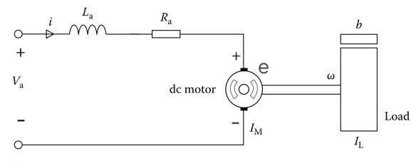
The controlled object in this study is a conveyor belt system driven by a direct current (DC) motor (Fig. 1).
The electro-mechanical model of system is shown in
Fig. 1. Torque T generated by the motor and back electromotive force (back EMF) e are described by the (1), (2):
| (1) |
| (2) |
where: T: Motor torque (N.m),  : Torque constant of the motor
  , i: Armature current (A), e: Back electromotive force (V),
  : Viscous friction constant of the motor
  ,
,  : Angular velocity of the motor shaft (rad/s)
Applying Kirchhoff's law for the armature circuit and Newton's 2nd law for the mechanical part, we have differential (3), (4) describing system:
| (3) |
| (4) |
where: J: Total moment of inertia of the motor rotor and conveyor system  , b: Viscous friction constant of the motor ,
  : Inductance of the motor winding
  ,
,  : Resistance of the motor winding
  ,
,  : Input armature voltage (V),
  : Angular acceleration (rad/
 ).
).
ApplyingLaplace transform, (3) and (4) can be expressed in terms of Laplace variables as (5), (6) follows:
| (5) |
| (6) |
Substituting  from (5) into (6), we get (7):
| (7) |
The transfer function of the system is obtained in (8):
| (8) |
While the real conveyor system inherently exhibits severe nonlinear characteristics such as static friction (stiction), dead zones at low voltages, and actuator saturation limits [3], an approximated linear model is deliberately extracted in this phase. The rationale for choosing a linear baseline over a highly complex nonlinear model is twofold: first, it provides a straightforward mathematical foundation for the initial tuning of the classic PID parameters; second, the unmodeled nonlinearities and dynamic disturbances are precisely the factors that the proposed adaptive Fuzzy-logic block is designed to compensate for in real-time. Therefore, a strictly nonlinear mathematical model is unnecessary for the proposed hybrid control architecture.
To obtain a model that is as close to reality as possible for simulation, the method of system identification from experimental input-output data is used.
The process (Fig. 2) is performed using the System Identification Toolbox in MATLAB. A multi-sine wave input voltage signal is chosen because it can excite the system at many different frequencies, helping the identified model to be more accurate over a wide frequency range.
Using the tfest (transfer function estimation) function configured for a continuous-time model with two poles and zero zeros (to match the theoretical 2nd-order structure in (7), The identification result yields the transfer function (9) of the real system as follows:
| (9) |
This transfer function has a high correlation with the experimental data (51.33% fit) and will be used to design and simulate the controller in the following sections.
The PID controller calculates the control signal u(t) based on three components: proportional (Proportional), integral (Integral), and derivative (Derivative) of the error e(t). This algorithm is shown in (10):
| (10) |
Fuzzy logic, initiated by Lotfi A. Zadeh, is a method of processing "uncertain" or "vague" information, close to human reasoning. Instead of two true/false values (1/0), fuzzy logic allows values in the range [0, 1].
A fuzzy control system consists of 4 main components structured as follows [11]:
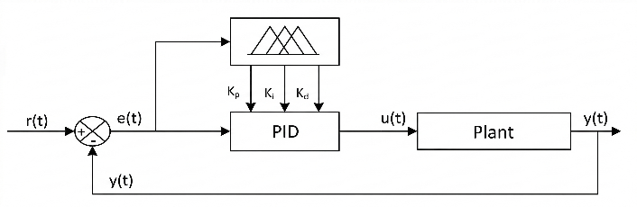
To overcome the drawbacks of PID and leverage the advantages of fuzzy logic, a hybrid Fuzzy-PID controller (Fig. 3) is designed. Its structure includes a conventional PID controller and a fuzzy logic controller (FLC). The FLC's task is to automatically tune the Kp, Ki, and Kd parameters based on the current state of the system, represented by the error E and the change in error CE.
FLC Inputs: error E and change in error CE, where: Error E is the difference between the setpoint speed and the actual speed. Change in error CE is calculated by the formula  .
.
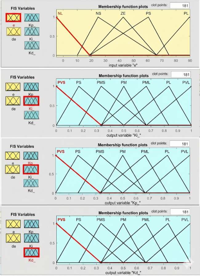
FLC Outputs: Correction values for Kp, Ki, Kd. The specific FLC design is as Fig. 4.
Fuzzification: The two input variables E and CE are divided into 5 fuzzy sets: Negative Large (NL), Negative Small (NS), Zero (ZE), Positive Small (PS), Positive Large (PL). The outputs Kp, Ki, Kd are divided into 7 fuzzy sets: Very Small (VS), Small (S), Medium Small (MS), Medium (M), Medium Large (ML), Large (L), Very Large (VL). Triangular and trapezoidal (shoulder) membership functions are used because of their computational efficiency and stable tracking performance in embedded applications [13].
Rule Base: 25 fuzzy rules are constructed for each output based on control experience and principles of parameter self-tuning [14]: increase Kp when the error is large, increase Ki when the error is small, and increase Kd when the change in error is large. The fuzzy rules for the 3 outputs Kp, Ki and Kd are presented in Table 1 to Table 3.
E / CE | NL | NS | ZE | PS | PL |
NL | VL | L | ML | M | MS |
NS | L | ML | M | MS | S |
ZE | ML | M | MS | S | VS |
PS | M | MS | S | VS | S |
PL | MS | S | VS | S | MS |
E / CE | NL | NS | ZE | PS | PL |
NL | VS | S | MS | M | ML |
NS | S | MS | M | ML | L |
ZE | MS | M | ML | L | VL |
PS | M | ML | L | VL | L |
PL | ML | L | VL | K | ML |
E / CE | NL | NS | ZE | PS | PL |
NL | MS | S | VS | S | MS |
NS | M | MS | S | VS | S |
ZE | ML | M | MS | S | VS |
PS | L | ML | M | MS | S |
PL | VL | L | ML | M | MS |
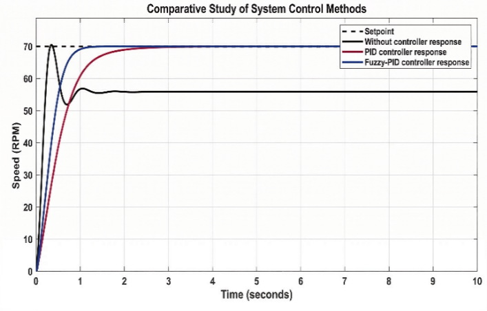
The Fuzzy-PID controller was built and simulated on MATLAB-Simulink using the identified transfer function. The results are compared with the open-loop system (no controller) and the system using a classic PID controller at a setpoint of 70 RPM. This comparison is shown in Fig. 5.
The simulation results (Table 4) show that the Fuzzy-PID controller achieves the best results. The system is not only stable (no overshoot, no steady-state error) but also has a fast response time (settling time of only 0.82s), almost twice as fast as the PID, demonstrating the intelligent self-tuning capability of the fuzzy block.
Parameters | No Controller | PID | Fuzzy-PID |
Overshoot (%) | 26.49 | 0 | 0 |
Rise Time (s) | 0.15 | 0.87 | 0.44 |
Steady-State Error (RPM) | 14.29 | 0 | 0 |
Settling Time (s) | 0.86 | 1.67 | 0.82 |
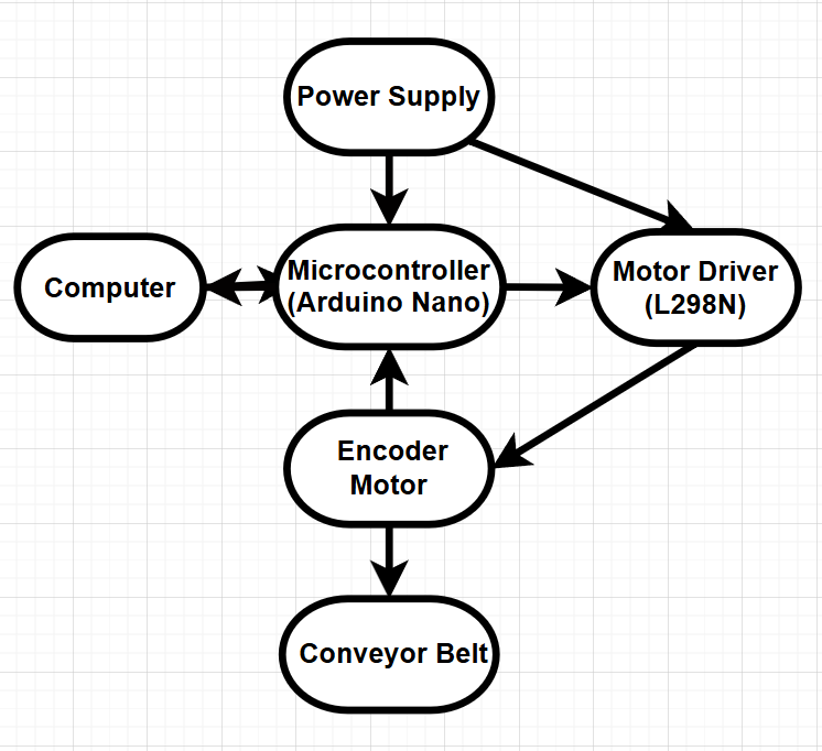
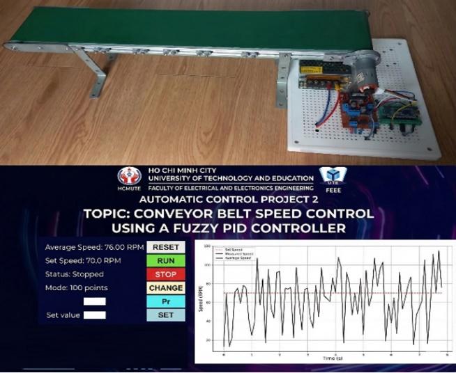
To verify theory, a practical conveyor belt model was constructed as in Fig. 6.
Hardware: The main components include an Arduino Nano V3 Microcontroller, a GA25-370 12V DC gear motor, an L298N H-bridge module, and a 12V-3A switching power supply.
Software and Real-time Implementation Challenges: The control algorithm is programmed in C/C++ on the Arduino IDE. Implementing continuous control laws on digital microcontrollers requires careful consideration of sampling time and signal discretization to ensure stability. Specifically, deploying a Fuzzy Inference System on a low-cost, 16 MHz microcontroller like the Arduino Nano presents significant computational complexity. The evaluation of 75 fuzzy rules (25 rules for each parameter Kp, Ki, Kd) and the execution of Center of Area (CoA) defuzzification consume considerable CPU cycles. To address this real-time challenge, the algorithm was heavily optimized using efficient discrete mapping and conditional branching. This optimization ensured that the execution time of the entire control loop was constrained strictly within the 10 ms sampling period, preventing buffer overflows, execution overruns, and maintaining the robustness of the system against dynamic parameter variations.
The user interface (GUI) (Fig. 7) is built using Python with the Tkinter library for control and Matplotlib for real-time plotting. To ensure consistency throughout the manuscript, all linguistic labels, buttons, and parameters on the GUI have been standardized to English. Communication between the computer and the Arduino is implemented via the UART serial standard.
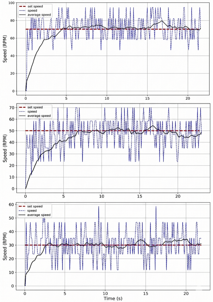
Experiments were conducted directly on the hardware model. The experimental results show that the Fuzzy-PID controller performs very well on the real model. The average speed of the conveyor belt closely tracks the setpoint, with no overshoot, fast response time, and small steady-state error across all speed ranges (30, 50, 70 RPM) (Fig. 8). This consistency across different operating points highlights the controller's robustness against varying dynamic friction, a common nonlinear disturbance in physical conveyor belts.
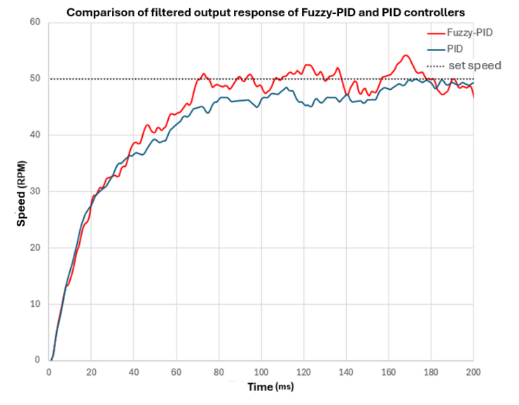
To evaluate further, a direct comparison experiment between the PID controller and the Fuzzy-PID controller was performed at a setpoint of 50 RPM (Fig. 9 and Table 3).
The comparison results on the real model once again confirm the superiority of the Fuzzy-PID controller. Specifically, Fuzzy-PID provides a 20% faster rise time (0.16s vs. 0.20s), a nearly 50% shorter settling time (0.56s vs. 1.08s), and significantly lower steady-state error (2.99 RPM vs. 4.70 RPM) compared to the PID controller, as shown in Table 5.
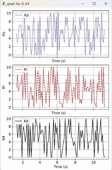
This superior performance can be explained by analyzing the adaptive tuning mechanism in real-time (illustrated in
Fig. 10). A critical limitation in physical conveyor systems is actuator saturation; the L298N motor driver has a maximum voltage limit (PWM = 255). During the initial start-up phase, when the speed error is maximum, a conventional PID's integral term accumulates rapidly, often leading to integral windup and subsequent overshoot. Conversely, the Fuzzy inference system intelligently mitigates this. According to the rule base (Table 2), when the error is Large, the Fuzzy block assigns a Very Small (VS) value to Ki, effectively preventing windup while maximizing Kp to accelerate the motor safely. As the speed approaches the setpoint (Error becomes Small), the Fuzzy block automatically increases Kd to increase system damping (preventing overshoot) and adjusts Ki upwards to eliminate the steady-state error caused by mechanical friction. This continuous, context-aware adjustment allows the Fuzzy-PID to navigate the physical constraints of the hardware far more gracefully than a fixed-gain controller.
Controller | Rise Time | Overshoot POT(%) | Settling Time | Steady-State Error |
Fuzzy-PID | 0.16 | 0 | 0.56 | 2.99 |
PID | 0.20 | 0 | 1.08 | 4.70 |
However, a multidimensional analysis reveals a necessary trade-off. While the Fuzzy-PID controller demonstrates clear superiority in control quality and robustness, it imposes a significantly higher computational burden. The real-time fuzzification, evaluation of 75 rules, and defuzzification processes consume considerably more CPU cycles and SRAM on the Arduino Nano compared to the simple arithmetic of a standard PID. In this specific conveyor application with a 10 ms sampling time, the hardware handles the load successfully. Yet, in highly dynamic industrial environments requiring extremely fast control loops (e.g., < 1 ms) or concurrent processing of multiple sensors, this computational overhead could become a hardware bottleneck, necessitating a migration to a more powerful microprocessor architecture (such as an ARM Cortex-M).
This paper successfully presents the design, simulation, and hardware implementation of an advanced conveyor speed control system using a hybrid Fuzzy-PID algorithm. The proposed system effectively overcomes the limitations of traditional PID controllers in nonlinear environments, demonstrating superior responsiveness and stability. Quantitative experimental results show significant performance enhancements: the rise time was reduced by 20% (to 0.16 s), the settling time was nearly halved to 0.56 s (a 48.1% improvement), and the steady-state error decreased by 36.4%. Furthermore, embedding the entire control algorithm on a microcontroller ensures practical applicability by enabling independent operation without computer-based computational support.
Despite these promising results, the current research relies heavily on empirical trial-and-error for designing fuzzy rules and membership functions. Additionally, the Arduino Nano hardware limits processing capabilities for high-speed applications, and the system is currently restricted to a laboratory scale. To address these limitations, future work will focus on integrating intelligent optimization algorithms, such as Genetic Algorithms (GA) or Particle Swarm Optimization (PSO), to systematically determine optimal fuzzy parameters. Upgrading to more powerful microcontrollers like the ESP32 or STM32 will also be necessary to support floating-point operations, faster sampling rates, and more complex computations.
Ultimately, future developments will aim to upgrade the system into a fully independent applied product by integrating load cells for dynamic weighing, vision systems for product classification, and standalone user interfaces. The results achieved in this study not only provide a highly effective solution for conveyor belt speed control but also highlight the significant potential of intelligent control methods in solving complex challenges within the field of industrial automation.
This research was funded by Ho Chi Minh City University of Technology and Engineering, Vietnam, under grant No. SV2026-284. We want to give thanks to Ms. Eng. Thi-Thanh-Hoang Le (HCM-UTE) for her supervision.
Minh-Nam Phan, Conveyor Speed Control with Fuzzy-PID