(1)
Journal of Fuzzy Systems and Control, Vol. 4, No 2, 2026 |
Design and Implementation of PID and Fuzzy-PID Controllers for Ball-on-Plate
Quoc-Khanh Tran 1, Pham-Minh-Trong Vo 2, Hoang-Dung Nguyen 3, Tran-Nhat Dang 4, Thi-Ngoc-Thao Nguyen 5,
Thi-Hong-Lam Le 6, Phong-Luu Nguyen 7, Thanh-Binh Nguyen 8,*, Van-Hiep Nguyen9, Ngoc-Long Le 10
1, 2, 3, 4, 5, 6, 7, 8, 9, 10 Ho Chi Minh City University of Technology and Engineering (HCM-UTE), Ho Chi Minh City (HCMC), Vietnam
Email: 1 23151124@student.hcmute.edu.vn, 2 23151195@student.hcmute.edu.vn, 3 23151067@student.hcmute.edu.vn,
4 23151152@student.hcmute.edu.vn, 5 thaontn@hcmute.edu.vn, 6 lamlth@hcmute.edu.vn, 7 luunp@hcmute.edu.vn,
8 binhnt@hcmute.edu.vn, 9 hiepnv@hcmute.edu.vn, 10 22151027@student.hcmute.edu.vn
*Corresponding Author
Abstract—This paper presents the design, implementation, and comparative evaluation of a conventional PID controller and a Fuzzy-PID controller for a nonlinear Ball-on-Plate (BoP). The primary objective is to stabilize the ball at a desired position on the plate while achieving a fast transient response and robustness against disturbances. A conventional PID controller is first designed and tuned using the Ziegler–Nichols method. To improve performance under nonlinear conditions, a Fuzzy-PID controller is developed in which fuzzy logic adaptively adjusts the PID gains online. The proposed controllers are evaluated through three stages: numerical simulation in MATLAB/Simulink, real-time implementation in Python, and experimental validation on a physical hardware platform. Compared with the conventional PID controller, the Fuzzy-PID controller achieves a reduction in maximum overshoot from 0.17% to below 0.1% in simulation, a shorter settling time (approximately 4.0 s for PID versus 2.8 s for Fuzzy-PID), and a reduction in steady-state positioning error of approximately 33–36% in hardware experiments (from ~3–14 pixels to ~2–9 pixels).
Keywords—Ball-on-Plate; PID Control; Fuzzy-PID Control; Nonlinear Systems; Intelligent Control; Ziegler–Nichols Tuning; MIMO Control
Modern control applications increasingly demand solutions for nonlinear, uncertain, and under-actuated dynamical systems. Such systems appear across robotics, aerospace, and industrial automation, where conventional linear control strategies often fail to deliver adequate performance [1], [2]. A fundamental challenge is the design of controllers that remain stable and accurate across a range of operating conditions, especially when the system exhibits coupling effects, parameter variations, and external disturbances [3], [4].
Among benchmark platforms for evaluating advanced control strategies, BoP has attracted significant research attention [5]-[7]. It is an extension of the classical Ball-and-Beam problem and represents a nonlinear, inherently unstable, and MIMO system in which a spherical ball must be stabilized on a flat plate whose inclination is controlled by two servo motors. The coupling between translational and rotational dynamics, actuator nonlinearities, and sensitivity to external disturbances make the BoP system a challenging and practically relevant testbed [5]-[7].
PID controllers remain the dominant control strategy in industrial practice because of their simplicity, reliability, and well-understood tuning procedures [1], [2], [7], [8]. However, fixed-gain PID controllers exhibit degraded performance when applied to nonlinear and time-varying systems [1], [2]. Issues such as overshoot, oscillations, and poor disturbance rejection become prominent when the operating point deviates significantly from the linearization point [4].
To overcome these limitations, intelligent control methods have been proposed. Fuzzy logic control (FLC) provides a model-free framework capable of encoding human expertise in the form of linguistic rules, making it well-suited for handling system nonlinearities and uncertainties [9], [10]. The Fuzzy-PID controller, which combines the simplicity of PID with the adaptability of fuzzy inference, has shown improved transient response and robustness in various nonlinear applications [11]-[14].
Previous studies on Ball-and-Beam and Ball-on-Plate systems have reported the effectiveness of Fuzzy-PID control in simulation [5], [6]. However, a key limitation in the existing literature is that most works focus primarily on simulation results without experimental validation on real-time hardware. Furthermore, few studies provide a rigorous multi-stage evaluation that bridges simulation, real-time software implementation, and physical hardware testing.
Fundamental background on nonlinear systems can be found in [15], while mechatronic system design principles for ball-based platforms are discussed in [16], [17]. Comprehensive handbooks on robotics [18] also provide relevant context for the BoP system. Specific studies on BoP control using PID [19] and hybrid fuzzy logic [20] have demonstrated the feasibility of real-time stabilization, further motivating the present comparative evaluation.
This paper addresses the aforementioned gap by presenting a comprehensive design, implementation, and comparative evaluation of PID and Fuzzy-PID controllers on a physical Ball-on-Plate platform. Unlike previous works that rely solely on simulation, this study provides a three-stage evaluation: MATLAB/Simulink simulation, real-time implementation in Python, and experimental validation on a hardware platform. The main contributions of this paper are as follows:
The remainder of this paper is organized as follows. Section II describes the BoP system and its mathematical modeling. Section III presents the PID controller design. Section IV introduces the Fuzzy-PID control strategy. Section V details the experimental setup and implementation. Section VI presents and discusses the simulation and experimental results. Section VII concludes the paper and outlines future research directions.
The Ball-on-Plate (BoP) system is an extension of the classical Ball-and-Beam problem and represents a nonlinear, under-actuated, and multi-input multi-output (MIMO) control system [5], [7]. The system consists of a rigid plate actuated by two servo motors that control the inclination angles along the x-axis and y-axis. A spherical ball rolls freely on the plate surface under the influence of gravity. The control inputs are the plate inclination angles θx and θy, which are indirectly generated by the servo motors. The system outputs are the Cartesian coordinates (x, y) of the ball position, measured using a vision-based sensing system.
To simplify the mathematical formulation while preserving the essential dynamics, the following assumptions are made:
Under these assumptions, the model focuses on the x-axis, and the same formulation applies symmetrically to the y-axis.
Key system parameters and control variables are summarized in Table 1.
Symbol | Description | Unit |
mb | Mass of the ball | kg |
Ib | Moment of inertia of the ball | kg·m² |
rb | Radius of the ball | m |
g | Gravitational acceleration (9.81 m/s²) | m/s² |
α | Plate inclination angle | rad |
x, y | Ball position coordinates on the plate | m |
θx, θy | Servo motor angles about x- and y-axes | rad |
ωn | Natural frequency of servo dynamics | rad/s |
ζ | Damping ratio of servo dynamics | — |
k | Geometric linkage constant | — |
Kp, Ki, Kd | Proportional, integral, and derivative gains | — |
e(t) | Tracking error: r(t) − y(t) | m |
ė(t) | Rate of change of error | m/s |
ΔKp, ΔKi, ΔKd | Fuzzy gain adjustment increments | — |
The dynamic behavior of the ball on the inclined plate is derived using the Euler–Lagrange approach. The Lagrangian function is defined as shown in (1):
| (1) |
where  is the total kinetic energy and
  is the potential energy of the system.
The total kinetic energy, consisting of translational and rotational components, is expressed in (2):
| (2) |
where  is the mass of the ball,
  is the moment of inertia, and
  is the angular velocity of the ball. For a solid spherical ball, the moment of inertia is given in (3):
| (3) |
The potential energy of the ball due to gravity is expressed in (4):
| (4) |
where  is the gravitational acceleration and
  is the plate inclination angle.
Applying the Euler–Lagrange equation is expressed in (5):
| (5) |
and assuming negligible generalized forces, the equation of motion for the ball along the  -axis can be obtained as (6):
| (6) |
For small inclination angles, the sine function can be linearized around the equilibrium point as shown in (7):
| (7) |
Thus, the linearized ball dynamics is expressed in (8):
| (8) |
The inclination angle is generated by the servo motor mechanism. The servo dynamics are modeled as a second-order system, which can be obtained as (9):
| (9) |
where  is the natural frequency and
  is the damping ratio of the servo system.
The geometric relationship between the servo angle  and the plate inclination is expressed in (10):
| (10) |
where  is a constant determined by the mechanical linkage between the servo arm and the plate.
The servo dynamics are modeled as a second-order system. The physical parameters of the experimental BoP are listed in Table 2.
By combining the ball dynamics and the servo actuation model, a control-oriented model suitable for PID and Fuzzy-PID controller design is obtained. The resulting system represents a cascaded structure consisting of servo dynamics followed by the ball motion dynamics.
Parameter | Value | Description |
ωn | 19 rad/s | Servo natural frequency |
ζ | 1.0 | Servo damping ratio (critically damped) |
F | 0.001 N·s/m | Rolling friction coefficient |
g | 9.81 m/s² | Gravitational acceleration |
dm | 0.017 m | Servo arm length |
dc | 0.062 m | Plate-to-linkage distance |
k = | 3.647 | Geometric linkage constant |
rb | 0.01 m | Ball radius (solid iron sphere) |
mb | 0.046 kg | Ball mass |
The PID control law is defined as [1], [3]:
| (11) |
where e(t) = r(t) − y(t) is the tracking error. Two independent PID controllers are implemented for the x- and y-axes, treating each as a SISO subsystem. In BoP, two independent PID controllers are implemented to regulate the ball position along the -axis and  -axis. Due to the decoupling assumption for small plate inclination angles, each axis is treated as a SISO subsystem.
The PID controller is designed based on the linearized control-oriented model derived in Section II. The control objective is to stabilize the ball at a desired position on the plate while minimizing overshoot, settling time, and steady-state error.
Since the BoP platform is inherently a complex MIMO system, a decoupling approach is adopted for small tilt angles, allowing the x and y axes to be actively controlled by two independent, parallel PID loops.
This systematic approach ensures a comprehensive understanding of the system's practical dynamic capabilities. The logic of the PID-based control method for the BoP system is illustrated in the flowchart shown in Fig. 1.
Given the second-order servo dynamics and the double-integrator nature of the ball motion, a properly tuned PID controller is required to ensure closed-loop stability and acceptable transient performance. In this study, the Ziegler–Nichols tuning method is adopted due to its simplicity and practical relevance for real-time implementation.
The initial and fine-tuned PID controller parameters for both axes are presented in Table 3.
Parameter | Kp | Ki | Kd | Sampling Time (s) |
X-axis (initial Z–N) | 6.0 | 8.625 | 2.156 | 0.0165 |
X-axis (fine-tuned) | 0.1 | ~0 (1×10⁻¹⁰) | 0.033 | 0.0165 |
Y-axis (initial Z–N) | 6.0 | 8.625 (not used; see text) | 2.156 | 0.0165 |
Y-axis (fine-tuned) | 0.1 | ~0 (1×10⁻¹⁰) | 0.033 | 0.0165 |
The Ziegler–Nichols ultimate gain method is applied to determine the initial PID parameters. The procedure can be summarized as follows:
 ,
,  ).
). until the closed-loop system reaches the stability limit, exhibiting sustained oscillations.
 and the corresponding oscillation period
  .
.Based on the obtained values of and , the PID parameters are computed using the standard Ziegler–Nichols formulas is expressed in (12)-(14):
| (12) |
| (13) |
| (14) |
These parameters provide an initial tuning that ensures closed-loop stability and reasonable transient response.
The tuned PID controllers are implemented independently for both axes of the Ball-on-Plate system. The controller outputs generate reference angles for the servo motors, which in turn adjust the plate inclination to correct the ball position.
In practice, further fine-tuning of the PID gains is performed experimentally to account for unmodeled dynamics, sensor noise, and actuator nonlinearities. The final controller parameters are selected to balance fast response and robustness while avoiding excessive oscillations.
The PID controller serves as a baseline control strategy for performance comparison with the proposed Fuzzy-PID controller presented in the next section.
Although the conventional PID controller provides satisfactory performance for linearized systems, its effectiveness degrades when applied to nonlinear and time-varying systems such as the Ball-on-Plate platform. The fixed PID gains are unable to adapt to changes in system dynamics, external disturbances, and coupling effects between the axes.
To address these limitations, a Fuzzy-PID controller is proposed. By integrating fuzzy logic with the PID structure, the controller gains can be adaptively adjusted based on the real-time system behavior. This approach enhances robustness and improves control performance under nonlinear operating conditions. Although the conventional PID controller provides satisfactory performance for linearized systems, its fixed gains are unable to adapt to changes in system dynamics, external disturbances, and coupling effects. To address these limitations, a Fuzzy-PID controller is proposed in which fuzzy logic adaptively adjusts the PID gains online [11]-[14].
Fuzzy-PID controller retains the classical PID control law while incorporating a fuzzy inference system (FIS) to tune the PID gains online. The control signal is expressed in (15):
| (15) |
where  ,
,  , and
, and  are time-varying gains determined by the fuzzy logic system.
The inputs to the fuzzy system are:


The outputs of the fuzzy system are the tuning factors for the PID gains, which modify the baseline PID parameters obtained from the Ziegler–Nichols method.
The fuzzy inference system is designed using the Mamdani approach due to its intuitive rule-based structure and suitability for real-time control applications. The implementation process of the proposed Fuzzy-PID control strategy is detailed in Fig. 2.
The input variables and are normalized and mapped into linguistic variables using triangular and trapezoidal membership functions. Each input is divided into five linguistic terms:
Similarly, the output variables corresponding to the PID gain adjustments are defined using five linguistic levels ranging from low to high values.
The fuzzy rule base is constructed based on expert knowledge and empirical observations of the Ball-on-Plate system behavior. A typical rule can be expressed as:
If the error is Positive Large and the error rate is Positive Small, then increase the proportional gain and derivative gain while slightly reducing the integral gain.
The complete rule base ensures:
Table 4 provides the fuzzy rule base used for the adaptive adjustment of the proportional gain (ΔKp).
NL | NS | ZE | PS | PL | |
NL | H | H | M | L | L |
NS | H | M | M | L | L |
ZE | M | M | L | M | M |
PS | L | L | M | M | H |
PL | L | L | M | H | H |
The inference mechanism employs the minimum operator for rule activation and the maximum operator for aggregation. The centroid method is used for defuzzification to obtain crisp values of the gain adjustment factors.
These factors are then applied to update the PID gains in real time according to (16)-(18):
| (16) |
| (17) |
| (18) |
where  ,
,  , and
, and  are the baseline PID gains.
The fuzzy-PID controller is implemented independently for the -axis and -axis of BoP. The fuzzy inference process is executed in real time using Python on Visual Studio Code, enabling seamless integration with the hardware platform.
To ensure stability and computational efficiency, the gain adjustment ranges are bounded, and the fuzzy inference system is optimized for real-time execution. This design allows the controller to adapt dynamically to variations in system dynamics and disturbances.
To comprehensively evaluate the performance of proposed controllers, BoP is tested through three progressive stages: numerical simulation, real-time software implementation, and experimental validation on a physical hardware platform. This multi-level evaluation framework ensures that the proposed control strategies are not only theoretically sound but also practically feasible.
By sequentially advancing from a purely virtual environment to full physical deployment, this methodology systematically isolates modeling inaccuracies from hardware-induced anomalies. Such a rigorous transition minimizes the risk of mechanical damage during the initial tuning phase while providing a transparent diagnostic pathway. Consequently, the correlation between theoretical predictions and empirical behaviors can be meticulously verified, thereby solidifying the reliability of the final comparative analysis.
The overall experimental architecture is illustrated in
Fig. 3, which includes the control algorithms, sensing subsystem, computation unit, and actuation mechanism.
The first stage of evaluation is conducted using MATLAB to validate the controller designs under ideal and disturbed conditions. The linearized mathematical model derived in Section II is implemented in MATLAB/Simulink.
This simulation serves as the baseline for performance evaluation is shown in Fig 4.
Both PID and Fuzzy-PID controllers are simulated using identical reference trajectories to ensure a fair comparison. Key performance metrics such as rise time, settling time, overshoot, and steady-state error are recorded. Disturbances and parameter variations are also introduced to assess controller robustness. The simulation results serve as a baseline for subsequent real-time and hardware experiments.
In the second stage, the control algorithms are implemented in Python and executed in real time using Visual Studio Code. This step bridges the gap between simulation and hardware deployment.
The Python-based implementation includes:
The modular software structure allows seamless switching between PID and Fuzzy-PID controllers while maintaining identical experimental conditions. This setup enables a direct and objective performance comparison between the two control strategies.
The final stage of evaluation is performed on a physical Ball-on-Plate hardware platform. The system consists of:
The vision system captures the real-time position of the ball and transmits the data to the control algorithm running on a host computer. The computed control signals are then sent to the servo motors to adjust the plate inclination accordingly.
To ensure repeatability and reliability, all experiments are conducted under identical initial conditions and reference trajectories for both controllers. The detailed specifications of the hardware components used in the Ball-on-Plate platform are summarized in Table 5.
Component | Specification |
Plate material | Rigid flat plate, 2-DOF linkage mechanism |
Servo motors | MG996R; stall torque 9.4 kgf·cm (4.8 V) / 11 kgf·cm (6 V); PWM 50 Hz, pulse 0.5–2.5 ms; range 0–180°; metal gear, dual ball bearing |
Ball | Solid iron sphere; radius rb = 0.01 m (diameter 20 mm); mass mb = 0.046 kg |
Vision sensor/camera | USB webcam; ~60 FPS; HSV color-space filtering (H: 5–26, S: 102–255, V: 142–255) |
Microcontroller/ | Arduino Uno R3 (ATmega328P, 16 MHz); host PC running Python via Visual Studio Code |
Control | ~16.5 ms (~60 Hz), determined by camera frame rate |
Communication interface | USB/UART; baud rate 115200 bps; Python serial.Serial to Arduino |
During real-time and hardware experiments, system responses are recorded and stored for post-processing and analysis. The following performance metrics are used to evaluate controller performance:
These metrics provide quantitative insight into the effectiveness and robustness of the PID and Fuzzy-PID controllers.
The performance of the PID and Fuzzy-PID controllers is first evaluated through MATLAB simulations using identical reference inputs and operating conditions. Both controllers are tested under nominal conditions and in the presence of external disturbances to examine their transient and steady-state characteristics.
The conventional PID controller is capable of stabilizing the ball position at the desired setpoint; however, the system exhibits noticeable overshoot, relatively long settling time, and oscillatory behavior, particularly when operating near nonlinear regions or during abrupt reference changes. These oscillations are primarily caused by the nonlinear dynamics of the Ball-on-Plate system and the fixed-gain nature of the PID controller.
In contrast, the Fuzzy-PID controller demonstrates improved transient performance. By adaptively adjusting the PID gains based on real-time error information, the controller responds aggressively to large deviations while maintaining smoother behavior near the equilibrium point. As a result, overshoot is significantly reduced and the settling time is shorter compared to the conventional PID controller.
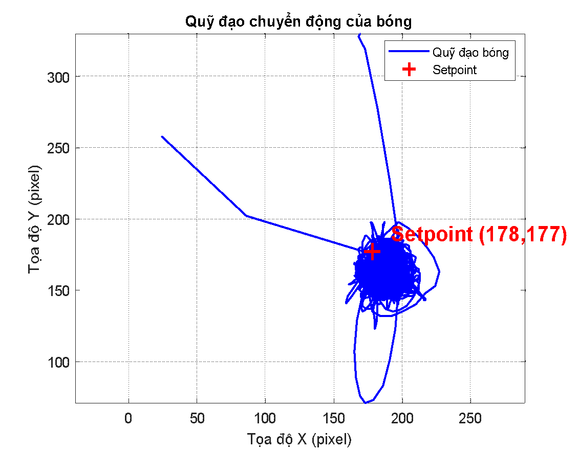
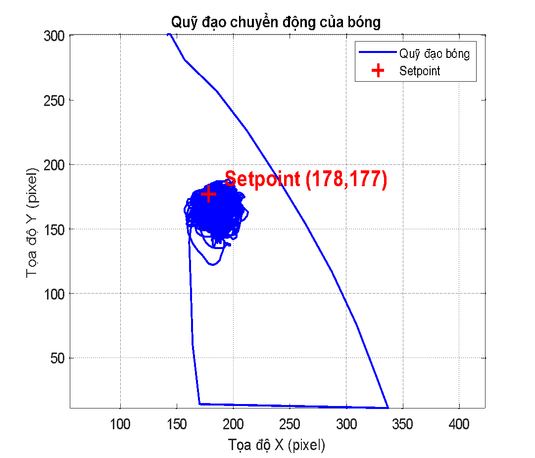
The simulated trajectories of the ball under PID and Fuzzy-PID control are compared in Fig. 5(a) and Fig. 5(b), respectively. The Fuzzy-PID controller achieves faster convergence with significantly reduced oscillations.
(a)
(b)
As shown in Fig. 5(a), the conventional PID controller leads to a long and oscillatory trajectory before the ball converges to the desired setpoint. In contrast, Fig. 5(b) illustrates that the Fuzzy-PID controller achieves faster convergence with significantly reduced oscillations.
To further validate the simulation findings, real-time control experiments are implemented using Python in Visual Studio Code under identical sampling and computational conditions. The results indicate that the PID controller provides acceptable performance for small reference changes but becomes sensitive to disturbances and measurement noise. Gain tuning presents a trade-off between fast response and stability, which limits the robustness of the controller in real-time operation.
The Fuzzy-PID controller exhibits superior adaptability in the software-based real-time environment. The online gain adjustment mechanism effectively compensates for modeling inaccuracies and external disturbances, resulting in smoother control actions and improved tracking accuracy. These observations are consistent with the simulation results and highlight the benefits of integrating fuzzy logic into the PID framework.
The most critical evaluation is conducted on the physical Ball-on-Plate hardware platform. Experimental results confirm that both controllers are capable of stabilizing the ball at the desired position; however, their performance differs significantly when exposed to real-world nonlinearities and uncertainties.
Under conventional PID control, the system response is characterized by noticeable oscillations during transient phases. Coupling effects between axes, actuator nonlinearities, sensor noise, and unmodeled dynamics lead to performance degradation compared to simulation results. In contrast, the Fuzzy-PID controller achieves faster stabilization with reduced oscillations, minimal overshoot, and improved steady-state accuracy. The adaptive nature of the controller allows it to handle hardware-induced disturbances more effectively, demonstrating its robustness in practical applications.
To further evaluate the control strategies beyond point stabilization, predefined reference trajectories are assigned to the system, including circular, figure-eight, and heart-shaped paths. For the circular trajectory, the ball successfully follows the reference path; however, deviations from the ideal trajectory are observed, particularly in regions with high curvature. These deviations can be attributed to system delays, limited actuator bandwidth, and frictional effects on the plate surface. Despite these challenges, stable tracking is maintained throughout the experiment, as shown in Fig 6.
The figure-eight trajectory introduces more frequent direction changes and increased dynamic coupling between axes. Larger tracking errors and oscillations are observed, especially near the trajectory intersection point. Nevertheless, the system remains stable, and the ball continues to follow the overall shape of the reference trajectory, revealing the limitations of decoupled axis control under highly dynamic conditions.
The circular trajectory tracking performance of the ball on the plate is illustrated in Fig. 7. Stable tracking is maintained despite deviations in high curvature regions. To assess generalization capability, a heart-shaped trajectory is employed as a highly nonlinear and non-standard reference. The ball is able to follow the overall shape of the trajectory, although tracking errors increase in regions with abrupt curvature changes. These errors are mainly caused by actuator saturation, sensor noise, and time delays in the vision-based feedback system. Importantly, closed-loop stability is preserved, and the ball remains within the plate boundary throughout the experiment.
Fig. 8 presents the tracking response for a figure-eight reference trajectory, revealing the limitations of decoupled axis control under highly dynamic conditions.
A comparative analysis of key performance metrics highlights the advantages of the proposed Fuzzy-PID controller over the conventional PID controller across all evaluation stages. The Fuzzy-PID controller consistently achieves reduced overshoot, shorter settling time, smoother control signals, and improved robustness against disturbances.
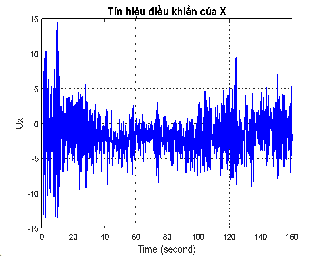
Fig. 9 further demonstrates that the Fuzzy-PID controller generates smoother control signals compared to the conventional PID controller, which exhibits higher amplitude fluctuations. A quantitative performance comparison of the PID and Fuzzy-PID controllers across all evaluation stages is provided in Table 6.
(a)
(b)
From the above results, the Fuzzy-PID controller consistently outperforms the conventional PID controller in terms of stability, tracking accuracy, and robustness against disturbances. While perfect trajectory tracking is not achieved due to physical constraints and modeling simplifications, the experimental outcomes confirm that the proposed control strategy is capable of handling both static and dynamic reference inputs.
The superior performance of the Fuzzy-PID controller can be attributed to its ability to adapt control gains based on real-time system behavior. Unlike fixed-gain PID controllers, the Fuzzy-PID approach effectively addresses nonlinearities and uncertainties inherent in BoP. While the Fuzzy-PID controller requires additional computational resources, the real-time implementation results indicate that the computational overhead is manageable and suitable for practical applications.
Metric | PID (Sim.) | Fuzzy-PID (Sim.) | PID (Exp.) | Fuzzy-PID (Exp.) |
Rise time (s) | ~2.1 | ~1.4 | N/A | N/A |
Settling time (s) | 4.0 | ~2.8 | ~8 | ~6 |
Max. | 0.17 | <0.1 | ~4 | ~2 |
Steady-state error (mm) | 0.15×10⁻³ m | <0.10×10⁻³ m | ~3 px (X), ~14 px (Y) | ~2 px (X), ~9 px (Y) |
Control signal smoothness | Oscillatory | Smooth | Oscillatory | Smoother |
This paper has presented the design and comparative evaluation of a conventional PID controller and a Fuzzy-PID controller for a nonlinear Ball-on-Plate system, validated through MATLAB simulation, real-time Python implementation, and physical hardware experiments.
The key findings of this study are as follows. First, the Fuzzy-PID controller consistently outperforms the conventional PID controller in overshoot reduction, settling time, and steady-state accuracy across all evaluation stages. Second, the adaptive gain-tuning mechanism based on fuzzy logic inference provides effective compensation for the nonlinear dynamics, actuator variations, and sensor noise inherent in the BoP platform. Third, the multi-stage evaluation framework demonstrates that the performance advantages of Fuzzy-PID control are preserved under real-world hardware conditions, not only in simulation. Specifically, the Fuzzy-PID controller reduced the maximum overshoot to below 0.1%, shortened the settling time from approximately 4.0 s to 2.8 s, and decreased the steady-state positioning error by 33–36% in physical hardware experiments compared to the conventional PID control. The primary limitation of this study is the use of axis decoupling, which introduces tracking errors under highly dynamic conditions with strong inter-axis coupling. Additionally, the vision-based feedback system introduces latency that limits control bandwidth, and the linearized model does not fully capture all nonlinear effects at large inclination angles.
Future work will focus on fully coupled MIMO control without axis decoupling, and on investigating learning-based approaches such as neural-fuzzy and reinforcement learning controllers. Performance under varying payloads and dynamic disturbances will also be explored to further assess scalability and robustness. Reducing vision-system latency through faster hardware or predictive sensing is another important direction.
This research was funded by Ho Chi Minh City University of Technology and Engineering, Vietnam, under grant No. SV2026-435. Link of operation of the system is: https://www.youtube.com/shorts/waTCcGBQifA.
Quoc-Khanh Tran, Design and Implementation of PID and Fuzzy-PID Controllers for Ball-on-Plate