Journal of Fuzzy Systems and Control, Vol. 4, No 1, 2026 |
Fuzzy-PID Control for Balancing a Two-Wheeled Inverted Pendulum Robot
Fahmizal 1, *, Afrizal Mayub 2, Lintang Fathia Rafanah 3, Smail Latifa 4
1,3 Department of Electrical Engineering and Informatics, Vocational College, Universitas Gadjah Mada,
Yogyakarta, Indonesia
2 Graduate School of Science Education, Universitas Bengkulu, Indonesia
4 LSETER Laboratory, Department Electrical Engineering, Nour Bachir University Center, El Bayadh, Algeria
Email: 1 fahmizal@ugm.ac.id, 2 afrizal.mayub@unib.ac.id, 3 lintangfathiarafanah2006@mail.ugm.ac.id,
4 l.smail@cu-elbayadh.dz
*Corresponding Author
Abstract—A two-wheeled inverted pendulum robot (TWIPR) requires continuous control action because its upright position is inherently unstable and highly sensitive to disturbances. This research proposes the use of a fuzzy-PID controller to keep the TWIPR balanced. Although PID has several advantages, its performance can degrade when the system is subjected to changing conditions. To address this, fuzzy logic is applied to enhance the adaptive capabilities of the PID controller. The fuzzy system dynamically generates PID parameters based on predetermined fuzzy rules, effectively maintaining system stability. The fuzzy membership functions used, namely MF3, MF5, and MF7, were compared through no-load and loaded tests. In the no-load test, the fuzzy-PID with MF7 reduced rise time, settling time, overshoot, peak value, and peak time by 1.229%, 0.673%, 86.703%, 7.232%, and 2.952%, respectively, compared with those of the conventional PID. However, the MF3 configuration only excels in overshoot and peak time, while the MF5 configuration only shows improvements in settling time, overshoot, and peak value. Further testing results show that Fuzzy-PID with MF7 provides the most stable performance under load conditions.
Keywords—Fuzzy-PID Controller; Two-Wheeled Inverted Pendulum Robot; Self-Balancing Control; Fuzzy Logic; PID Controller
Robotics has become an important technological field in modern industries because it supports automation, improves operational efficiency, and encourages the development of intelligent systems [1]. Robotics can create innovations in the development of new technologies that can potentially change lives and the environment [2], [3]. Two-wheeled inverted pendulum robots (TWIPR) are a subclass of mobile robots characterized by their inherent instability and unique configuration, resembling the dynamics of an inverted pendulum mounted on two wheels. Research in this area has been carried out, for example, in [4], [5].
The design of TWIPR and its range of applications, which include educational media, rehabilitation, mobile surveillance, and delivery robots, make this system an interesting topic in academic research [6]-[8]. With its high flexibility and adaptability, this robot has the potential to be used in various industrial applications as well as public services. The ability of TWIPR to adapt quickly to changing environmental conditions is an important advantage, especially in the fields of airport transportation, logistics, and healthcare, where flexibility and reliability are key factors [9]. However, stability control can remain a major challenge for TWIPR due to unstable performance. The robot must actively control its motors to maintain balance [10], [11]. The main difficulty is seen in achieving stable performance under various conditions, including external disturbances, terrain variations, and system uncertainties. Due to the nonlinear characteristics of TWIPR systems, conventional control methods such as PID (Proportional-Integral-Derivative) can experience performance degradation when system parameters change.
Although PID controllers have been widely used due to their minimalism and efficiency, they are not yet optimal in handling nonlinear systems and systems whose parameters change over time [12]. According to a report in [13], PID controllers still face difficulties in parameter tuning and robustness to condition variations. To overcome these challenges, several optimization methods have been applied [14]-[16], whereas a hybrid approach integrating PID control with fuzzy logic has also been introduced [17], [18]. With its ability to handle uncertainty and nonlinear behavior, fuzzy logic is an effective method for improving control performance [19].
In recent years, studies on control systems in TWIPR have been widely developed. For example, research in [20] applied the Linear Quadratic Regulator (LQR) method to stabilize and control TWIPR. The results showed that LQR was able to maintain system stability and produce good control performance. Furthermore, research in [21] utilized Genetic Algorithm (GA) to optimize LQR, thus obtaining increased control efficiency, shorter stabilization time, and smoother system response. Meanwhile, another study in [22] proposed the use of a Kalman Filter that was further optimized with the Fish Swarm Algorithm and combined with state feedback control to control TWIPR. The results of this study showed that the process of filtering disturbances and measurement noise can improve output accuracy in automatic balancing robots.
The system’s state-space model was identified by utilizing MATLAB’s System Identification Toolbox. This technique was used to facilitate the implementation process in the next stage. This modeling method is known as black box modeling, because it only utilizes the system's input and output data, as described in [23]. A similar approach has also been used in TWIPR modeling in studies [24], [25].
This research has several key contributions, as follows:
The structure of this paper is as follows. Section II describes the TWIPR system modeling process. Section III discusses the proposed fuzzy-PID controller design. Section IV presents the test results and analysis. Section V presents the conclusions of this research.
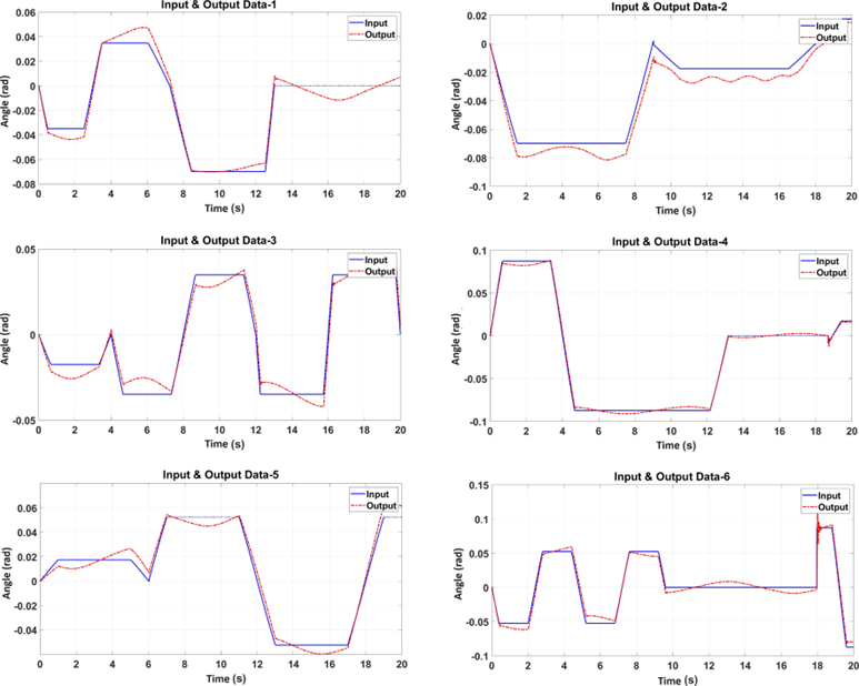
The TWIPR model identification process in this study was conducted based on input-output data obtained from Simscape Multibody simulations. A black-box approach was used to identify the dynamic relationship between system inputs and outputs without requiring a prior understanding of its internal structure [23]-[25]. In this study, black-box modeling was performed using MATLAB's System Identification Toolbox (SIT), which is capable of estimating and validating nonlinear models from SISO and MIMO data to produce a more accurate representation of system dynamics [26]. To excite the system, the Multi-Level Periodic Perturbation Signal (MLPPS) method was used, namely a complex input signal with frequency variations that aims to produce more informative and diverse identification data, as shown in Fig. 1.
Input-output data from various variations are then imported into SIT for model estimation and validation purposes. The identification process begins with the data import stage, followed by selecting the model structure and determining the number of poles and zeros used. Model validation is performed by comparing the response of the modeling results with the response obtained from measurements output and calculating the best fit percentage for each variation. Models with higher fit values indicate a better fit to the actual data. Thus, the estimation and validation results through SIT produce a transfer function model that could be used to better comprehend the performance and pattern of the control system.
In this identification process, all data variations are also used for cross-validation, so that each variation plays a role in validating the other variations. In addition to generating transfer function models for each variation, the best fit percentage of each model is also evaluated. As shown in Table 1, the fifth transfer function (TF5) provides the lowest average error value compared to the other transfer functions. This finding indicates that the fifth variation dataset has a higher level of accuracy in representing system dynamics compared to the other variation datasets. Therefore, the TF5 model that describes the TWIPR system in open-loop conditions is presented in (1).
Validation data | |||||||
Data-1 | Data-2 | Data-3 | Data-4 | Data-5 | Data-6 | Mean | |
TF1 | 16.87 | 22.27 | 19.26 | 5.78 | 14.12 | 16.24 | 15.75 |
TF2 | 20.36 | 16.66 | 23.07 | 15.7 | 17.61 | 22.69 | 19.34 |
TF3 | 18.12 | 27.09 | 17.83 | 4.83 | 15.1 | 18.1 | 16.84 |
TF4 | 17.4 | 26.42 | 18.37 | 3.79 | 14.56 | 15.77 | 16.05 |
TF5 | 16.87 | 22.67 | 19.05 | 5.41 | 14.11 | 16.13 | 15.7 |
TF6 | 16.44 | 26.71 | 18.58 | 3.83 | 14.6 | 15.67 | 15.97 |
The transfer function model in this study was obtained using the MATLAB System Identification Toolbox, utilizing system input-output data. This approach allows the TWIPR dynamics to be empirically modeled without the need for analytical derivation of physical equations. The obtained transfer function is written as follows:
| (1) |
In this research, a simulation environment was developed utilizing Simscape Multibody in MATLAB version R2023b. This tool supports the creation of physical models of mechanical systems based on three-dimensional (3D) components that can interact directly. Thus, this approach allows simulations to more accurately depict the dynamics of mechanical systems and provides a reliable platform for analysis, testing, and research.
The simulation environment in this project was systematically designed to accurately approximate real-world conditions. The simulation's realism was enhanced by adjusting several key parameters, including the physical interactions between components, the direction and magnitude of Earth's gravitational acceleration, and the material properties of the model. These adjustments are expected to more realistically represent the system's operating conditions.
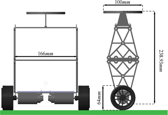
Prior to the simulation phase, a 3D CAD model of the TWIPR was developed. The model included the main components of the chassis and wheels connected by rotational joints. Fig. 2 shows this configuration, detailing the design and integration of each robot component within the simulation environment. This configuration enables comprehensive testing and assessment of the robot’s performance under various conditions, resulting in more reliable and effective simulation results.
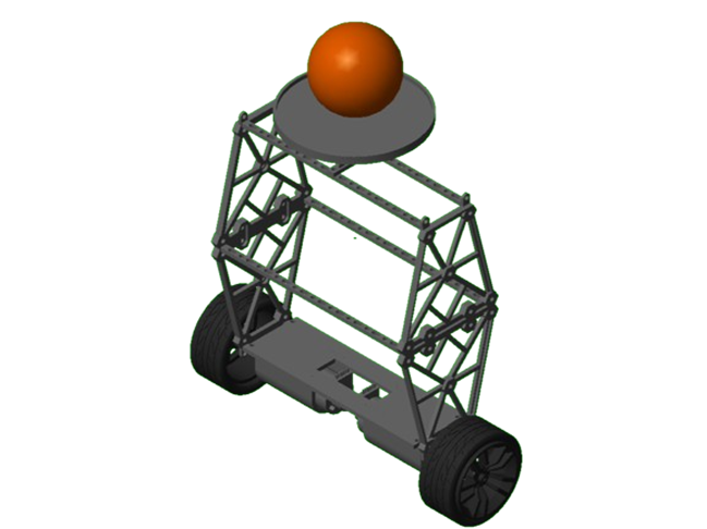
In the next stage, the robot was tested with various loads in the form of balls weighing 50-grams, 75-grams, and 100-grams. The interaction between the robot, the floor, and the balls was physically represented using spatial contact force blocks. This modeling allowed the simulation to depict the effect of changes in load mass on the robot's performance and stability more realistically. With this physical interaction simulation, the robot's response to various load conditions can be analyzed to support design improvements and control strategies, thereby increasing the stability and reliability of the robot's operation. The condition of the robot while carrying a load is shown in Fig. 3.
Classical PID tuning approaches, including Ziegler-Nichols and Kitamori-based methods, are relatively simple to apply, but their fixed gain values can limit controller adaptability under changing operating conditions [27]. This can reduce the reliability of the control system under dynamic environments, especially when the system is affected by environmental variations. By utilizing fuzzy logic, the control system can have better flexibility and responsiveness in dealing with these fluctuating conditions.
The use of fuzzy logic to auto-tuning PID controllers was introduced by Zhao [28]. In this method, the error  and the error rate of change ė are used as input variables to form fuzzy rules and inference mechanisms. This study adapts this concept to support a more effective fuzzy decision-making process. Furthermore, several fuzzy logic configurations with different numbers of membership functions are implemented to examine their influence on control system performance. Performance assessment is carried out by considering aspects of convergence speed, response to disturbances, and overall system stability. The goal of this approach is to improve the adaptability of the control system to variations in environmental dynamics, particularly in the case of an inverted pendulum robot.
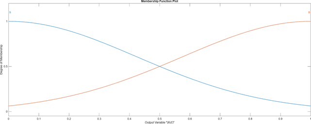
The output parameter membership functions for the output parameters  and
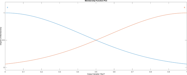
and  are designed using the MacVicar-Whelan configuration [29]. The membership functions for e(k) and ė(k) include: negative big (NB), negative medium (NM), negative small (NS), zero (ZO), positive small (PS), positive medium (PM), and positive big (PB). For and , two membership functions are used: small (S) and big (B).
and are the output parameters of the fuzzy system, normalized from the values of  and
and  . The normalization process is carried out through a linear transformation to ensure that both parameters are in the range 0 and 1, as shown in (2) and (3). These normalized parameters are then used in further calculations to obtain the actual values of and applied to the system.
| (2) |
| (3) |
The minimum and maximum limits for and indicate the range of permissible parameter values and are determined experimentally. Meanwhile, the parameter  is not determined in the same way as and but is calculated based on the integral time constant
  , which is formulated as follows:
| (4) |
With the known equations, the actual PID gain values are derived as follows.
| (5) |
| (6) |
| (7) |
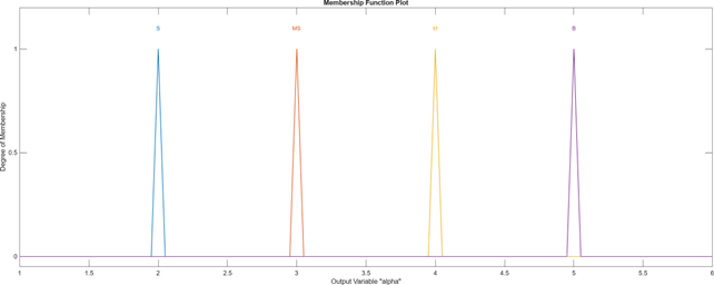
The constant α is set to a different value for each category, namely “2” for small (S), “3” for medium small (MS), “4” for medium (M), and “5” for big (B). The membership function representation used is discrete and is called a singleton representation [28].
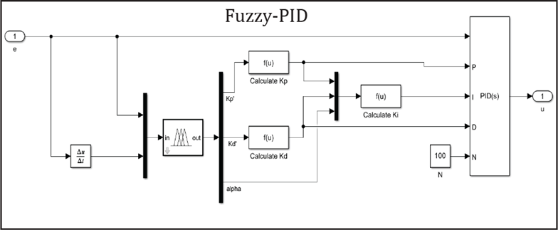
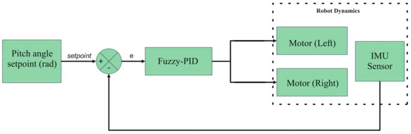
In the simulation phase, fuzzy logic is implemented using Simulink and integrated with the PID block to produce a fuzzy-PID control scheme. This integration allows adaptive tuning of PID parameters through fuzzy logic rules, so that the control system can respond better to changing conditions. This controller design is intended to enhance the robot’s stability and responsiveness. The system implementation in the MATLAB Simulink block is shown in Fig. 4, whereas the complete diagram of the proposed fuzzy-PID controller for the TWIPR is shown in Fig. 5.
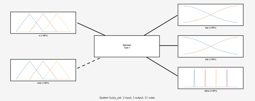
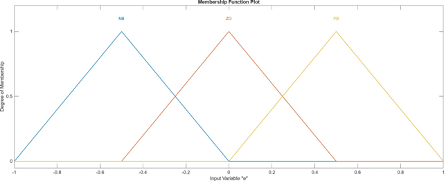
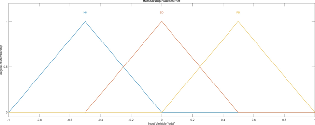
Through Fuzzy Logic Designer, a fuzzy inference system (FIS) tree plot is obtained as shown in Fig. 6. The representation of membership functions for input variables with three membership functions (MF3) is presented in more detail in Fig. 7 and Fig. 8. Meanwhile, the representation of membership functions for output variables is shown in Fig. 9 to Fig. 11.
MF3 employs three input membership functions for both e(k) and ė(k). These three membership functions result in a total of nine fuzzy rules for each output membership function:, , and α. The relationship between the input and output membership functions forms a fuzzy rule table, which is shown in Table 2, Table 3, and Table 4.
For a wheeled inverted pendulum system, the system's dynamic behavior is highly sensitive around the equilibrium point, particularly when the angle is zero or vertical. A triangular membership function, with its single, sharp peak, allows small changes in input errors, such as the tilt angle, to result in significant changes in the membership degree. This increases the controller's sensitivity to small deviations, making it crucial for maintaining system stability.
, when , when On the other hand, a trapezoidal membership function has a flat region, or plateau, where small input changes do not significantly affect the membership value. Consequently, the controller's response in this region can be less sensitive, potentially reducing the system's stabilization performance.
 (MF3)
(MF3)ė(k) | ||||
e(k) | NB | ZO | PB | |
NB | B | B | B | |
ZO | S | B | S | |
PB | B | B | B | |
(MF3)ė(k) | |||||
e(k) | NB | ZO | PB | ||
NB | S | S | S | ||
ZO | B | B | B | ||
PB | S | S | S | ||
ė(k) | ||||
e(k) | NB | ZO | PB | |
NB | S | S | S | |
ZO | B | MS | B | |
PB | S | S | S | |
The next fuzzy model development was carried out by applying five membership functions, referred to as MF5. In this configuration, each input variable, e(k) and ė(k), is represented by five membership functions. Meanwhile, the output structure remains the same as the MF3 model. From the combination of these input membership functions, the MF5 model generates 25 fuzzy rules. Details of the obtained fuzzy rules are shown in Table 5 for , Table 6 for , and Table 7 for α.
The final fuzzy configuration developed in this study uses a seven-membered fuzzy function (MF7). The rules in this model are arranged based on Table 8, Table 9, and Table 10. In the MF7 configuration, the input part is represented by MF7 functions, while the output structure still follows the design used in the MF3 model.
Fuzzy tuning rules are designed based on system errors as a basis for adaptively adjusting control outputs. These rules are designed to generate stronger control actions when system errors are large, while reducing the intensity of control actions when the system approaches steady state. Thus, this approach is expected to improve overall system response and minimize oscillations. Under conditions of large errors, for example, higher control output values are applied to accelerate the deviation reduction process.
(MF5)ė(k) | ||||||
e(k) | NB | NS | ZO | PS | PB | |
NB | B | B | B | B | B | |
NS | S | B | B | B | S | |
ZO | S | S | B | S | S | |
PS | S | B | B | B | S | |
PB | B | B | B | B | B | |
(MF5)ė(k) | ||||||
e(k) | NB | NS | ZO | PS | PB | |
NB | B | S | B | S | B | |
NS | B | B | S | B | B | |
ZO | S | S | B | B | S | |
PS | B | B | S | B | B | |
PB | B | S | B | S | B | |
 (MF5)
(MF5)ė(k) | ||||||
e(k) | NB | NS | ZO | PS | PB | |
NB | S | S | S | S | S | |
NS | M | MS | S | MS | M | |
ZO | B | MS | MS | MS | B | |
PS | M | MS | S | MS | M | |
PB | S | S | S | S | S | |
(MF7)ė(k) | ||||||||
e(k) | NB | NM | NS | ZO | PS | PM | PB | |
NB | B | B | B | B | B | B | B | |
NM | S | B | B | B | B | B | S | |
NS | S | S | B | B | B | S | S | |
ZO | S | S | S | B | S | S | S | |
PS | S | S | B | B | B | S | S | |
PM | S | B | B | B | B | B | S | |
PB | B | B | B | B | B | B | B | |
(MF7)ė(k) | ||||||||
e(k) | NB | NM | NS | ZO | PS | PM | PB | |
NB | S | S | S | S | S | S | S | |
NM | B | B | S | S | S | B | B | |
NS | B | B | B | S | B | B | B | |
ZO | B | B | B | B | B | B | B | |
PS | B | B | B | S | B | B | B | |
PM | B | B | S | S | S | B | B | |
PB | S | S | S | S | S | S | S | |
(MF7)ė(k) | ||||||||
e(k) | NB | NM | NS | ZO | PS | PM | PB | |
NB | S | S | S | S | S | S | S | |
NM | MS | MS | S | S | S | MS | MS | |
NS | M | MS | MS | S | MS | MS | M | |
ZO | B | M | MS | MS | MS | M | B | |
PS | M | MS | MS | S | MS | MS | M | |
PM | MS | MS | S | S | S | MS | MS | |
PB | S | S | S | S | S | S | S | |
The fuzzy rule tables are formulated from heuristic control principles and observations of the TWIPR response, where the controller output is adjusted according to the magnitude and trend of the error signal. Two input variables, namely the error  ) and the rate of change of error
  , are used to determine the appropriate tuning values for the controller parameters. In conditions where the error is large or increasing, a larger tuning value is given to produce a stronger control action so that the error can be reduced more quickly. Conversely, when the error is relatively small or the system response has approached the reference value, a smaller tuning value is chosen to prevent excessive control action, overshoot, or oscillation. Therefore, this rule table is designed to achieve a balance between the speed of the transient response and the stability of performance at steady state.
For example, when is in the PB or NB category and error shows that the error is still experiencing quite large changes, so a higher tuning value is chosen to speed up the system response. On the other hand, when is in the ZO category or close to zero, a smaller tuning value is used so that the control action remains smooth and prevents instability.
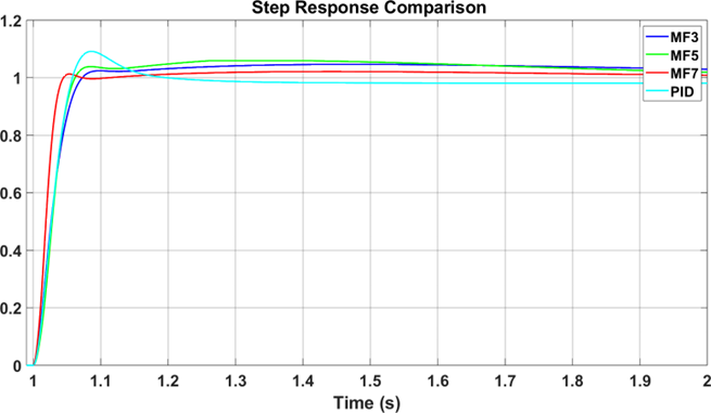
A manually tuned conventional PID controller is used as a baseline to validate the performance of the proposed control method. The simulation results for the no-load test are shown in Fig. 12. As seen in the figure, all fuzzy configurations are able to reduce the steady-state error compared to the conventional PID controller. Further analysis of the step response characteristics for each controller is presented in Table 11. Based on these results, the Fuzzy-PID with the MF7 configuration shows the best performance in all response parameters. Compared to the conventional PID, this configuration successfully reduces the rise-time, settling-time, overshoot, peak, and peak-time by 1.229%, 0.673%, 86.703%, 7.232%, and 2.952%, respectively. Meanwhile, the Fuzzy-PID with MF3 only provides improvements in the overshoot and peak-time parameters, while the Fuzzy-PID with MF5 shows improvements in settling-time, overshoot, and peak value.
Characteristic | Performance comparison | |||
PID | MF3 | MF5 | MF7 | |
Rise time (s) | 1.058 | 1.074 | 1.062 | 1.045 |
Settling time (s) | 1.338 | 1.341 | 1.335 | 1.329 |
Overshoot (%) | 0.091 | 0.044 | 0.059 | 0.012 |
Peak | 1.091 | 1.044 | 1.059 | 1.012 |
Peak time (s) | 1.084 | 1.356 | 1.271 | 1.052 |
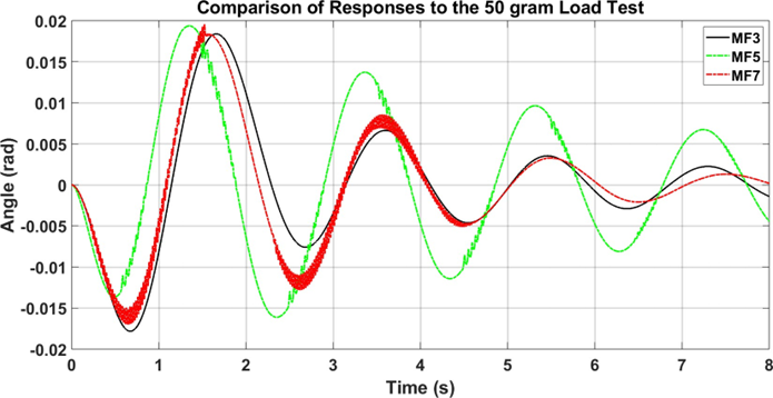
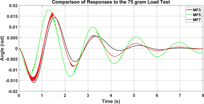
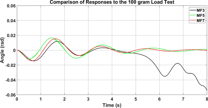
The comparative results of the load tests are shown in Fig. 13 to Fig. 15. Based on the test data, MF7 was identified as the most effective model in minimizing steady-state error. This model consistently demonstrated the best performance, producing the lowest final error values for each load scenario compared to other fuzzy models. The errors obtained were 0.0012 for a 50-gram load, 9.1663×10⁻⁶ for a 75-gram load, and 3.1332×10⁻⁶ for a 100-gram load. However, it should be noted that in the test with a 100-gram load, the MF3 model failed to achieve stability, causing the robot to lose balance and subsequently overturn.
The findings of this study indicate that the fuzzy model can provide better performance than a conventional PID controller tuned using a trial-and-error approach in minimizing steady-state error. Among all the configurations evaluated, the MF7 model demonstrated the most optimal performance in handling varying load conditions, with very low error values in each test scenario. This effectiveness demonstrates the potential of the MF7 for application in robot control systems, especially in applications that require high precision and stability.
Conversely, the inability of the MF3 model to maintain stability under the 100-gram load test demonstrates the limitations of fuzzy configurations with a smaller number of membership functions. Therefore, selecting an appropriate configuration and tuning fuzzy parameters are crucial aspects in developing robust and efficient control systems. Overall, this study reinforces the importance of utilizing fuzzy logic in improving control system performance.
As shown in Fig. 14, the system response to the 75-gram load test shows that the Fuzzy-PID controller has the ability to produce a shorter steady-state time and lower oscillations compared to other membership function configurations, namely MF3 and MF7. These results indicate that the proposed controller is able to maintain system stability under moderate load conditions.
Furthermore, Fig. 15 shows that increasing the load up to 100 grams causes the system response to experience greater oscillations, especially in the MF3 configuration, thus indicating reduced system stability. However, the Fuzzy-PID controller still shows a more stable response when compared to the conventional configuration. These results confirm that the proposed method has better resilience to load changes.
The TWIPR simulation in this study was developed in the Simscape Multibody environment, with 3D models imported and integrated directly into the system. A black-box approach was used to obtain the system transfer function based on input-output data. Furthermore, fuzzy logic was applied to the PID controller to improve the adaptive characteristics of the control system. The controller performance was evaluated by comparing the variation of the number of membership functions on the fuzzy inputs, namely MF3, MF5, and MF7. Compared with a conventional PID controller, Fuzzy-PID controller with MF7 configuration shows performance improvement through decreasing rise time, overshoot, peak value, and peak time by 1.229%, 0.673%, 86.703%, 7.232%, and 2.952%, respectively. Meanwhile, Fuzzy-PID with MF3 only excels in overshoot and peak time aspects, while MF5 configuration provides improvements in settling time, overshoot, and peak value. Based on these results, the MF7 configuration produces the most stable performance, especially under loading conditions.
Fahmizal, Fuzzy-PID Control for Balancing a Two-Wheeled Inverted Pendulum Robot