Journal of Fuzzy Systems and Control, Vol. 4, No 2, 2026 |
Comparative Evaluation of Fuzzy Logic, Sliding Mode, and LQR Controllers for DC Motor
Position Control
Minh-Thy Pham 1, Lam-Trong-Tuan Bui 2, Thi-Thanh-Hoang Le 3,*, Van-Bac Nguyen 4, Le-Khoi-Nguyen Cao 5,
Le-Nhat-Minh Tran 6, Xuan-Manh Ngo 7, Phong-Luu Nguyen 8, Dinh-Phu Nguyen 9
1, 2, 3, 4, 5, 6, 7, 8, 9 Ho Chi Minh City University of Technology and Engineering (HCM-UTE), Ho Chi Minh City (HCMC), Vietnam
Email: 1 2531108@student.hcmute.edu.vn, 2 2531109@student.hcmute.edu.vn, 3 hoangltt@hcmute.edu.vn,
4 22142082@student.hcmute.edu.vn, 5 21142135@student.hcmute.edu.vn, 6 21142129@student.hcmute.edu.vn,
7 22142027@student.hcmute.edu.vn, 8 luunp@hcmute.edu.vn, 9 22142195@student.hcmute.edu.vn
*Corresponding Author
Abstract—This paper presents a comparative evaluation of three advanced control strategies for DC motor position control, namely Fuzzy Logic Control (FLC), Sliding Mode Control (SMC), and Linear Quadratic Regulator (LQR). First, the mathematical model of the DC motor is derived from the electrical and mechanical dynamic equations. Based on this model, the three controllers are designed and implemented in MATLAB/Simulink and experimentally validated on a microcontroller-based platform under identical operating conditions. The comparative analysis is performed using quantitative performance indices, including settling time, overshoot, steady-state error, and control effort. Simulation and experimental results show that the SMC controller provides the best overall performance with fast convergence, high robustness, and small steady-state error, while the FLC approach achieves smoother responses with moderate transient performance. The LQR controller demonstrates rapid state regulation but produces larger transient peaks and higher control effort compared with the other methods. The results highlight the practical trade-offs among intelligent, robust, and optimal control strategies for low-cost DC motor position control applications.
Keywords—DC Motor; Fuzzy Logic Control; Sliding Mode Control; LQR; Position Control; Advanced Control
Direct current (DC) motors remain one of the most widely used actuators in robotics, industrial automation, conveyors, electric drives, and mechatronic systems because of their simple construction, favorable torque characteristics, and ease of speed and position regulation [1]. In practical motion-control applications, however, achieving satisfactory position performance is not limited to reference tracking alone. A high-quality controller is also expected to provide short settling time, low overshoot, small steady-state error, and sufficient robustness against load disturbances, parameter variations, and unmodeled nonlinear effects [1].
Classical proportional–integral–derivative (PID) control is still widely adopted in DC motor systems because of its simple structure and straightforward implementation [1]. Nevertheless, when the controlled plant is affected by uncertainty, disturbance, or nonlinear operating conditions, classical linear tuning methods may no longer provide the desired trade-off between tracking accuracy, robustness, and control effort. For this reason, many recent studies have investigated advanced control methods for DC motor position regulation, especially intelligent control, robust nonlinear control, and optimal state-feedback control [2]-[4].
Among these advanced approaches, Fuzzy Logic Control (FLC) has attracted considerable attention because it can incorporate heuristic knowledge and linguistic rules without
requiring an exact mathematical model of the plant [5]. This feature makes fuzzy control especially suitable for systems with modeling uncertainty and parameter variation. In contrast, Sliding Mode Control (SMC) is well known for its robustness against matched disturbances and plant uncertainty, and has been widely applied to motor positioning systems requiring fast dynamic response and strong disturbance rejection [6], [7]-[11]. The Linear Quadratic Regulator (LQR), on the other hand, provides an optimal linear state-feedback framework in which the control law is obtained by minimizing a quadratic performance index, thereby offering a systematic compromise between tracking performance and control energy [12], [13]-[16].
Although these three methods have all been studied individually in the literature, their dynamic characteristics are fundamentally different. Fuzzy control emphasizes flexibility and knowledge-based design, sliding mode control emphasizes robustness and insensitivity to uncertainty, and LQR emphasizes optimality for state regulation under a given model and weighting structure. Therefore, a comparative study using the same DC motor plant and the same reference profile is valuable for clarifying the practical trade-offs among tracking accuracy, transient response, robustness, and control effort [3], [8].
Motivated by this need, this paper investigates the angular position control of a DC motor using three representative advanced control strategies: Fuzzy Logic Control (FLC), Sliding Mode Control (SMC), and Linear Quadratic Regulator (LQR). First, the mathematical model of the DC motor is derived from the armature circuit equation and the mechanical torque balance equation. Next, the theoretical principles of the three controllers are presented and implemented in MATLAB/Simulink for comparative simulation analysis. Finally, the controllers are experimentally validated on a microcontroller-based platform under identical operating conditions. The comparative evaluation is conducted using quantitative performance indices, including settling time, overshoot, steady-state error, and control effort, in order to analyze the tracking performance, transient response, and robustness characteristics of the three control methods for DC motor position regulation.
Recent studies have investigated advanced control strategies such as Sliding Mode Control (SMC), optimal control, and intelligent control methods for improving DC motor position regulation performance [17]-[20].
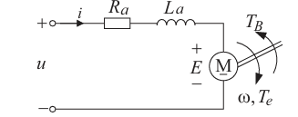
The direct current (DC) motor is an electromechanical system in which electrical energy is converted into mechanical rotational motion. The dynamic behavior of the motor can be described by combining the electrical dynamics of the armature circuit and the mechanical dynamics of the rotor, as shown in Fig. 1.
The armature circuit of the DC motor consists of the armature resistance  , armature inductance
  , and the back electromotive force (back-EMF). According to Kirchhoff’s voltage law, the electrical equation of the motor can be expressed as,
| (1) |
where  is the armature voltage,
  is the armature current, and
  represents the back electromotive force generated by the motor.
The back electromotive force is proportional to the angular velocity of the motor shaft and can be written as,
| (2) |
where  is the back-EMF constant and
  denotes the angular speed of the rotor.
The mechanical dynamics of the DC motor are determined by the torque balance acting on the rotor. According to Newton’s rotational law, the mechanical equation can be written as,
| (3) |
where  is the rotor moment of inertia,
  is the viscous friction coefficient,
  is the electromagnetic torque generated by the motor, and
  represents the external load torque.
The electromagnetic torque produced by the motor is proportional to the armature current and can be expressed as,
| (4) |
where  is the torque constant of the motor.
By combining the electrical and mechanical equations and neglecting the load torque for nominal analysis, the transfer function between the armature voltage and the angular speed  can be obtained in the Laplace domain as.
| (5) |
This transfer function represents the dynamic relationship between the input voltage and the rotational speed of the DC motor and forms the basis for the design of control algorithms used in this study.
Table 1 presents the parameters of the DC motor used in this study.
Parameter | Symbol | Value |
Armature resistance |
| 0.6 Ω |
Armature inductance |
| 0.012 H |
Torque constant |
| 0.8 Nm/A |
Back-EMF constant |
| 0.8 Vs/rad |
Rotor inertia |
| 0.0167 kg·m² |
Viscous friction |
| 0.0167 |
Based on the mathematical model derived in Section II, three control strategies are considered for DC motor position regulation: Fuzzy Logic Control, Sliding Mode Control, and Linear Quadratic Regulator.
Fuzzy Logic Control is an intelligent control method based on linguistic rules rather than an exact mathematical model [3]. A fuzzy controller generally consists of four main blocks:
In DC motor position control, the usual inputs of the fuzzy controller are the position error and the change of error:
| (6) |
| (7) |
where  is the angle of motor and
  is the expected angle.
The controller output is the control voltage:
| (8) |
Typical linguistic labels for fuzzy sets are {NB, NM, NS, ZE, PS, PM, PB}, representing negative big, negative medium, negative small, zero, positive small, positive medium, and positive big. For a fair comparative evaluation, all controllers were implemented under identical operating conditions, including the same DC motor parameters, reference trajectory, sampling time, supply voltage, and experimental setup. In the fuzzy controller design, the input variables consist of the position error and the change of error, while the output variable represents the control voltage. Triangular membership functions with seven linguistic labels {NB, NM, NS, ZE, PS, PM, PB} were used for all variables. The same operating conditions and reference signals were also maintained for the SMC and LQR controllers to ensure consistency and validity in the comparative analysis. The membership functions are typically chosen as triangular or trapezoidal shapes. The main strength of fuzzy control is that it can handle uncertainties and nonlinear behavior without requiring a highly accurate model. However, its performance strongly depends on the design of membership functions and control rules.
Sliding Mode Control is a robust nonlinear control method belonging to the class of variable structure systems [12]. The key idea is to define a sliding surface such that when the system state reaches this surface, the desired closed-loop dynamics are obtained.
Define the tracking error as:
| (9) |
A common sliding surface is:
| (10) |
where  is a design parameter.
The control law is typically expressed as:
| (11) |
where  is the equivalent control and
  is the switching component:
| (12) |
To reduce chattering in practical implementation, the sign function is often replaced by a saturation function:
| (13) |
where  is the boundary layer thickness.
SMC is known for its robustness to parameter variations and external disturbances. Its main drawback is chattering, which may affect actuators if not properly mitigated
The Linear Quadratic Regulator is an optimal state-feedback control method for linear systems [2]. Consider the state-space model:
| (14) |
| (15) |
The LQR control law is:
| (16) |
where the gain matrix  is chosen to minimize the quadratic cost function:
| (17) |
Here,  is a positive semi-definite weighting matrix on the states and
  is a positive definite weighting matrix on the control input. The optimal feedback gain is obtained from:
| (18) |
The matrix 𝑃 is obtained by solving the algebraic Riccati equation.
| (19) |
The LQR method provides a systematic trade-off between state regulation and control effort. It is highly effective when the system model is available in state-space form.
To complement the experimental study, a simulation-based evaluation was carried out in MATLAB/Simulink for the same DC motor plant and for the same three control strategies considered in this paper, namely Fuzzy Logic Control (FLC), Sliding Mode Control (SMC), and Linear Quadratic Regulator (LQR). The simulation model was built using the motor parameters listed in Table 1, while the controller structures followed the theoretical formulations introduced in Section III. The objective of the simulation study was to provide a clearer comparison of the transient behavior, tracking capability, and control effort of the three controllers before practical implementation.
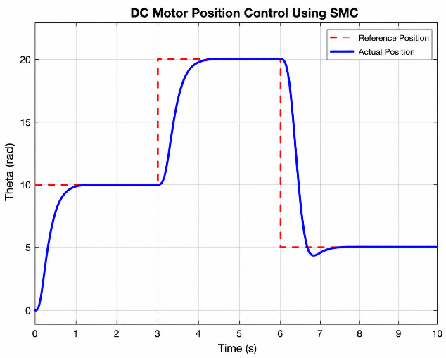
For consistency, all controllers were evaluated using the same simulation conditions and reference trajectory. The simulation was implemented in MATLAB/Simulink using the DC motor parameters listed in Table 1. The reference position profile consisted of step changes from 10 rad to 20 rad and then to 5 rad during the simulation interval. The same sampling conditions, motor model, and operating voltage were maintained for all controllers to ensure a fair comparison. In addition, the controller parameters, including fuzzy membership functions, SMC switching gains, and LQR weighting matrices, were selected based on stable closed-loop performance and tracking accuracy.
For all controllers, the same piecewise-constant reference position profile was applied in order to ensure a fair comparison. Based on the provided simulation plots, the reference angle was set to 10 rad at the beginning of the simulation, and increased to 20 rad at  s, and then reduced to 5 rad at
  s. In addition to the position response, the motor angular speed and armature current were also observed, since these two variables provide important information about control aggressiveness and actuator demand. Such a simulation procedure is consistent with prior DC motor control studies, where the same plant is tested under identical references to compare intelligent, robust, and optimal controllers under equivalent operating conditions [3].
To further evaluate the effectiveness of the proposed fuzzy logic controller before hardware implementation, a MATLAB/Simulink model was developed for the DC motor position control system. The simulation model was constructed based on the motor dynamics presented in Section II and on the fuzzy control principle introduced in Section III, where the position error and the change of error are used as the main inputs to the fuzzy inference mechanism. This simulation framework makes it possible to examine the controller behavior under reference changes and to observe how the fuzzy rule base generates the corresponding control action.
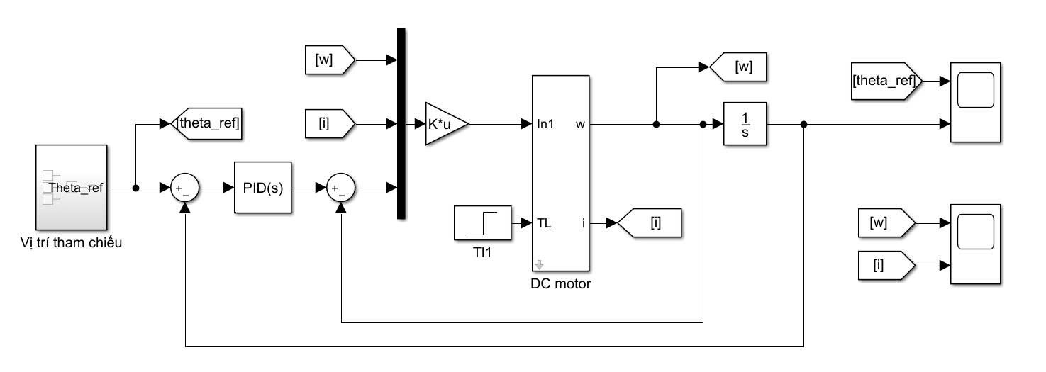
The overall simulation structure of the fuzzy-controlled system is shown in Fig. 2. In this model, the reference position is compared with the actual angular position to generate the tracking error, and the processed fuzzy output is then applied to the DC motor model. In addition to the position response, the angular speed and armature current are also monitored in order to assess not only the tracking capability but also the control effort required by the fuzzy controller.
After establishing the simulation model, the fuzzy logic controller was tested using a step-varying reference position profile in order to evaluate its transient and steady-state characteristics. The objective of this simulation is to determine whether the controller can maintain accurate position tracking while preserving smooth dynamic behavior when the reference changes abruptly.
The simulation results of the fuzzy logic controller are presented in Fig. 3 and Fig. 4, where the position response, angular speed, and armature current are illustrated. These responses provide a basis for evaluating the quality of the fuzzy control strategy in terms of tracking accuracy, overshoot, settling behavior, and the magnitude of the corresponding control action.
The simulation response of the fuzzy logic controller shows that the motor position is able to follow the reference trajectory with relatively smooth tracking performance over the three operating regions. During the transition toward 10 rad, the response exhibits approximately 4–6% overshoot before settling near the reference value. A similar transient characteristic is observed during the step change from 10 rad to 20 rad. In the final transition from 20 rad to 5 rad, the response remains stable with only a small steady-state offset observed from the plot. Overall, the fuzzy controller provides smooth position regulation with moderate settling performance; however, its convergence is slower and its tracking accuracy is slightly lower than that achieved by the SMC controller.
The speed and current responses of the fuzzy controller indicate that the control action is relatively oscillatory under the present tuning. The angular speed reaches large transient peaks in both positive and negative directions, while the armature current also shows pronounced spikes and ripple during the switching instants of the reference. This suggests that, although the fuzzy controller can achieve good nonlinear tracking performance, the selected rule base and scaling gains still require further tuning in order to reduce control effort and improve damping. This observation is in line with the fuzzy-control literature, where the final performance
strongly depends on membership design, scaling, and inference rules [3]-[7].
In order to investigate the robustness of the sliding mode controller under the same operating conditions, a dedicated simulation model was also implemented in MATLAB/Simulink. The controller was designed according to the sliding surface formulation presented in Section III, in which the tracking error and its derivative are used to construct the switching law. This approach enables the closed-loop system to force the state trajectory toward the predefined sliding surface and maintain the desired motion behavior.
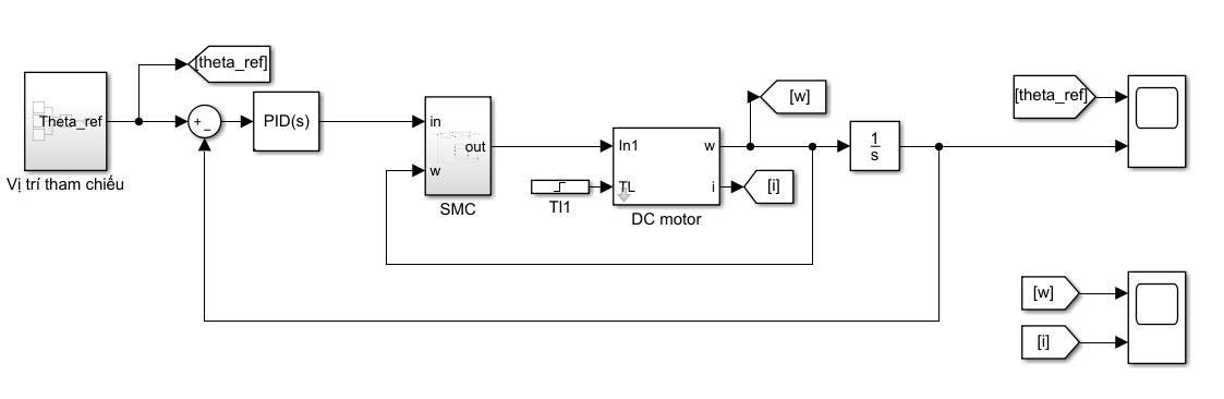
The Simulink structure of the DC motor position control system using Sliding Mode Control is depicted in Fig. 5. The block diagram highlights the interaction between the position reference, the tracking error, the SMC law, and the DC motor plant. Such a model is useful for examining the effect of the switching control action on the motor response, especially during sudden reference variations and during the transition toward the sliding surface.
Based on the constructed simulation model, the sliding mode controller was subjected to the same reference profile used for the fuzzy controller so that a fair comparison could be made. This allows the transient response, steady-state tracking performance, and robustness characteristics of SMC to be examined under identical simulation conditions.
The corresponding simulation results are shown in Fig. 6 and Fig. 7. These figures present the angular position response together with the speed and current signals, thereby allowing the influence of the switching control law to be observed more clearly. In particular, the results help reveal both the main advantage of SMC, namely fast and robust tracking, and its potential drawback related to oscillatory switching behavior.
The sliding mode controller demonstrates the fastest and most stable tracking performance among the three simulated controllers. From the position response, the system reaches the reference rapidly in all operating regions, with approximately 1–3% overshoot and very small steady-state error. During the downward transition from 20 rad to 5 rad, the controller exhibits slight undershoot but quickly recovers and settles near the desired reference value. Compared with the fuzzy controller, the SMC approach provides faster convergence and improved tracking precision while maintaining moderate transient behavior. These results indicate that the SMC controller achieves a favorable balance between tracking performance, robustness, and control effort.
The corresponding speed and current plots confirm the strong dynamic performance of the SMC design. Although short transient peaks appear during abrupt reference changes, their magnitude is considerably lower than that obtained in the fuzzy case, and the response decays more cleanly. A slight oscillatory behavior can still be noticed around the switching intervals, which is consistent with the well-known chattering phenomenon of sliding mode control. Even so, the overall simulation suggests that SMC offers the best compromise between fast tracking, robustness, and reasonable control effort for the present DC motor model. This is consistent with prior work on DC motor and servo positioning, where SMC is repeatedly reported as a robust method with excellent disturbance rejection but some residual chattering near the sliding surface [8]-[13].
For the Linear Quadratic Regulator, the simulation study was carried out using the model of the DC motor introduced in Section II and the optimal control formulation described in Section III. The LQR controller was implemented as a state-feedback law in which the gain matrix is selected through the solution of the algebraic Riccati equation, providing a systematic balance between tracking performance and control effort.
The overall simulation structure of the LQR-based position control system is shown in Fig. 8. In this model, the reference position is compared with the measured motor position, while the feedback states are used to compute the optimal control signal. This simulation arrangement allows the effectiveness of the LQR method to be observed in terms of fast correction capability, response smoothness, and the magnitude of the resulting actuator demand.
Using the above simulation model, the LQR controller was tested under the same sequence of reference changes as the fuzzy and sliding mode controllers. The purpose of this evaluation is to analyze how the optimal controller responds to step variations in the desired position and to determine whether the selected weighting matrices provide a suitable compromise between speed of response and control energy.
The simulation results obtained for the LQR controller are presented in Fig. 9 and Fig. 10. These figures show the motor position tracking performance as well as the associated speed and armature current responses. Through these plots, the dynamic characteristics of the LQR approach can be assessed and directly compared with those of the fuzzy logic and sliding mode controllers.
The LQR-based simulation exhibits very fast positional convergence, especially during the upward transition from 10 rad to 20 rad. However, compared with the FLC and SMC controllers, the LQR response produces approximately 10–15% overshoot during the rising transition and noticeable undershoot after the downward step from 20 rad to 5 rad. In addition, the speed and current responses show significantly higher transient peaks, indicating increased control effort and actuator demand. Although the controller achieves rapid state regulation, the transient behavior is less smooth than that obtained using the SMC controller. These characteristics suggest that the selected LQR weighting matrices prioritize fast tracking performance at the expense of smoother transient response and reduced control effort.
This aggressiveness becomes even more evident in the speed and current plots. The motor angular speed exhibits extremely large peaks, and the armature current rises to very high values compared with the other controllers. Therefore, while the present LQR tuning yields fast state regulation in simulation, it does so at the expense of a very large control effort. In practical implementations, such behavior may be undesirable unless actuator saturation, current limitation, and additional weighting adjustments are explicitly considered. This interpretation agrees with the LQR literature, where the final performance depends strongly on the selection of the weighting matrices Q and R, since these matrices
determine the trade-off between tracking quality and control energy [14]-[18].
A comparative examination of the three simulation results indicates that each controller has a distinct performance characteristic, as shown in Table 2. The fuzzy controller achieves acceptable tracking and a relatively smooth position response, but its speed and current plots reveal higher oscillation and larger control demand than expected under the present tuning. The sliding mode controller offers the best overall compromise, since it combines fast convergence, small steady-state error, and moderate control effort, although a slight chattering effect is still visible. The LQR controller, on the other hand, produces the fastest nominal correction in position, but also generates the most severe speed and current peaks, which reduces its practical attractiveness unless additional constraints are introduced.
Controller | Overshoot (%) | Settling Time (s) | Steady-State Error | Control Effort | Remarks |
FLC | ~4–6% | ~0.8 s | Small | Moderate | Smooth response with moderate oscillation |
SMC | ~1–3% | ~0.4 s | Very small | Moderate | Fast and robust response with slight chattering |
LQR | ~10–15% | ~0.3 s | Very small | High | Fast response but larger transient peaks |
From the simulation perspective alone, the sliding mode controller can be considered the most effective controller for the present study because it preserves both tracking quality and robustness without causing the excessive control effort observed in the LQR case. The fuzzy controller remains attractive because of its model-free nature and flexible design, but further optimization of the membership functions and scaling gains is necessary to improve its transient performance. The LQR controller remains theoretically elegant and efficient for state regulation, yet the current results indicate that its weighting matrices should be retuned to obtain a more realistic compromise between fast response and actuator limitation.
In simulation, all three controllers were able to track the desired position profile; however, their transient characteristics were significantly different. The FLC controller produced moderate settling performance with relatively smooth position tracking, although noticeable speed and current oscillations were still observed. The SMC controller achieved the smallest overshoot and fastest settling behavior among the three methods while maintaining moderate control effort. In contrast, the LQR controller provided rapid state regulation but generated larger transient peaks in both speed and current responses, indicating higher actuator demand and control effort.
To validate the proposed control strategies, a DC motor position control system was implemented in a laboratory environment. The experimental setup is designed to evaluate the performance of the Fuzzy Logic Control, Sliding Mode Control, and Linear Quadratic Regulator under practical operating conditions. The overall hardware configuration of the system is illustrated in Fig. 11.
The experimental system consists of a DC motor, a motor driver module, a microcontroller unit, and a regulated power supply. The DC motor serves as the controlled plant, while the microcontroller executes the control algorithms and generates the control signals.
As shown in Fig. 11, the main components of the setup include:
The power supply delivers the electrical energy required for the motor operation, while the motor driver regulates the armature voltage according to the control signal generated by the microcontroller. The encoder attached to the motor shaft provides feedback information used to measure the angular position for closed-loop position control.
In the experiments, the DC motor was supplied with a 12 V DC source, and the control algorithms were executed using a fixed sampling interval of 10 ms within the Arduino environment. The encoder feedback was used to continuously measure the angular position for closed-loop control implementation.
The control algorithms are implemented in a discrete-time framework within the microcontroller environment. At each sampling instant, the motor position is measured and compared with the reference position to compute the tracking error.
For the fuzzy logic controller, the position error and the change of error are processed through the fuzzy inference system to generate the control signal. In the sliding mode controller, the sliding surface is calculated based on the tracking error, and the control law drives the system states toward the desired sliding surface. For the LQR controller, the control input is determined by the optimal state-feedback gain obtained from the solution of the Riccati equation.
The computed control signal is then converted into a PWM duty cycle, which regulates the voltage applied to the DC motor through the motor driver module. All controllers were implemented under identical experimental conditions, including the same reference trajectory, hardware configuration, supply voltage, and sampling conditions, in order to ensure a fair comparative evaluation.
To compare the effectiveness of the proposed control methods, several quantitative performance indices were considered. The controller performance was evaluated using settling time, overshoot percentage, steady-state error, and transient control effort obtained from both simulation and experimental responses. These evaluation criteria provide an objective basis for comparing the tracking performance and transient behavior of the Fuzzy Logic Control (FLC), Sliding Mode Control (SMC), and Linear Quadratic Regulator (LQR) methods in DC motor position regulation.
This section presents the experimental results obtained from the DC motor position control system implemented on the home experimental platform. The three control strategies—Fuzzy Logic Control (FLC), Sliding Mode Control (SMC), and Linear Quadratic Regulator (LQR)—were tested under identical operating conditions in order to evaluate their tracking performance and robustness.
The motor position response was recorded for different reference values. The experimental data were analyzed using several performance criteria, including settling time, overshoot, and steady-state error. These indices allow a quantitative comparison of the effectiveness of the control methods.
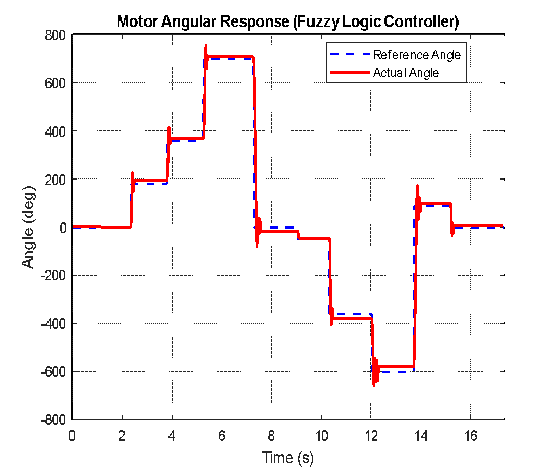
The angular response of the DC motor using the Fuzzy Logic Controller is shown in Fig. 12. The dashed blue line represents the reference angle, while the solid red line indicates the measured motor angle. From the results, the motor angle follows the reference trajectory closely throughout the experiment. When the reference signal changes in a step-like manner, the actual angle tracks the desired value with a small steady-state error. A slight overshoot can be observed during several transitions; however, the system quickly stabilizes and converges to the reference value.
Overall, the fuzzy logic controller provides stable and smooth tracking performance for the DC motor system.
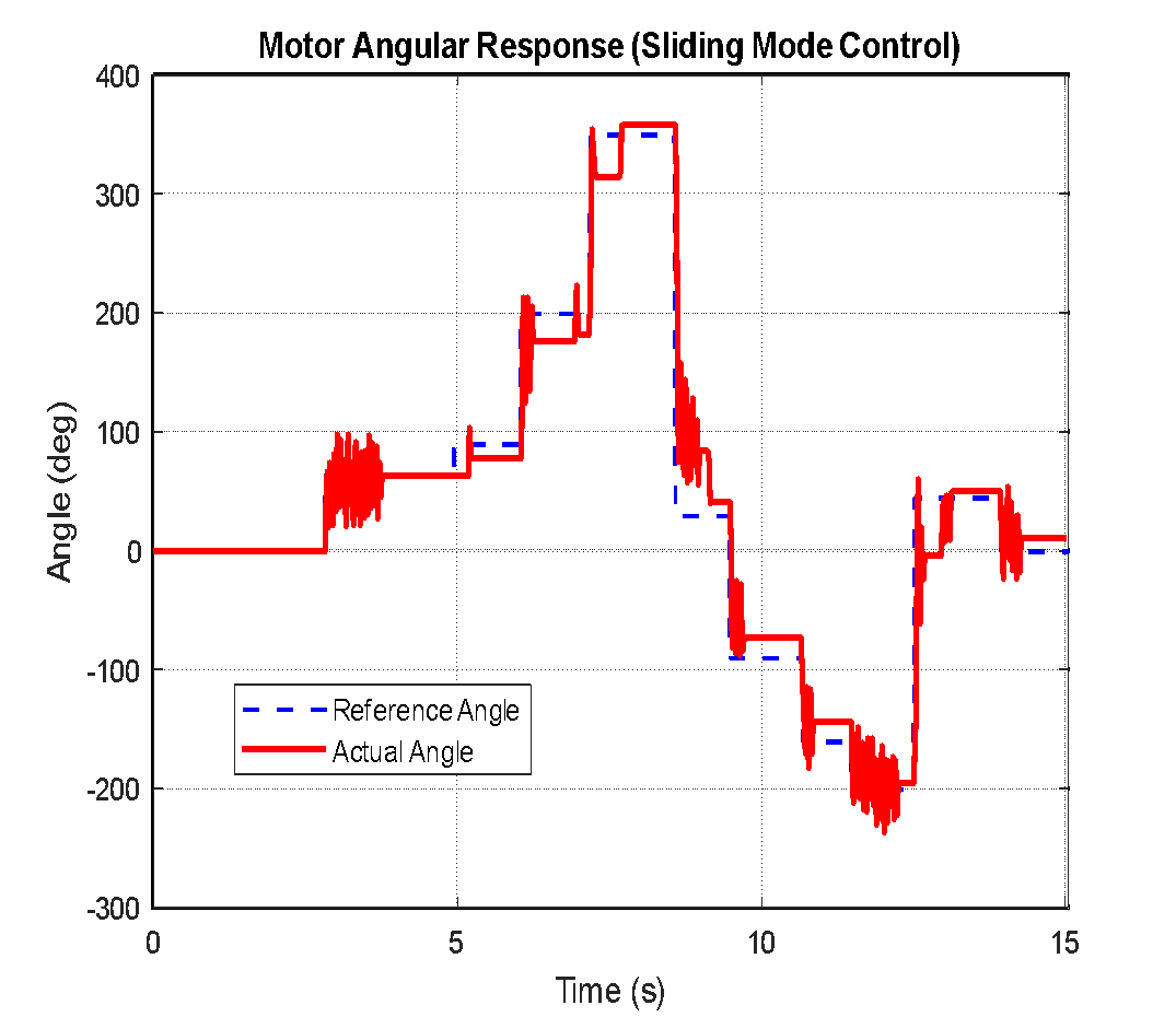
The angular response of the DC motor using the Sliding Mode Controller is shown in Fig. 13. The dashed blue line represents the reference angle, while the solid red line indicates the measured motor angle. From the results, the controller is able to track the reference trajectory with a fast response. However, noticeable oscillations appear during some transitions due to the switching nature of the sliding mode control law. This phenomenon, commonly known as chattering, is typical in SMC systems. Despite this effect, the controller still maintains good tracking performance and acceptable steady-state accuracy.
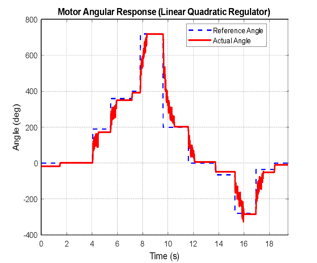
The angular response of the DC motor using the Linear Quadratic Regulator is shown in Fig. 14. The dashed blue line represents the reference angle, while the solid red line indicates the measured motor angle. The controller is able to track the reference trajectory with relatively good accuracy. A small overshoot and oscillation can be observed during some transitions; however, the response quickly converges to the desired value. Overall, the LQR controller provides satisfactory tracking performance for the DC motor system.
From Table 3, the FLC controller provides relatively smooth tracking performance with moderate settling characteristics and stable operation under practical conditions. The SMC controller achieves the most robust tracking behavior with fast convergence, although slight chattering is observed due to the switching control action. The LQR controller also provides rapid tracking performance but exhibits larger transient oscillations during sudden reference changes.
Controller | Experimental Behavior | Stability | Practical Observation |
FLC | Smooth tracking with moderate response speed | Stable | Simple implementation with moderate oscillation |
SMC | Fast and robust tracking response | Highly stable | Slight chattering observed during switching |
LQR | Rapid response with larger transient peaks | Moderately stable | Higher transient oscillation and actuator demand |
Experimental and simulation results confirmed that all three controllers were capable of tracking the reference position under identical operating conditions; however, their transient characteristics were significantly different. The FLC controller provided relatively smooth tracking performance with approximately 4–6% overshoot and moderate settling behavior. The SMC controller achieved the fastest convergence and the smallest transient error among the evaluated methods, although slight chattering was observed due to the switching control action. In contrast, the LQR controller provided rapid state regulation but produced larger transient oscillations and approximately 10–15% overshoot during sudden reference changes. These results demonstrate the trade-offs among intelligent, robust, and optimal control strategies for DC motor position regulation.
We want to give thanks to Ph.D. Van-Dong-Hai Nguyen (HCM-UTE) due to his supervision.
Minh-Thy Pham, Comparative Evaluation of Fuzzy Logic, Sliding Mode, and LQR Controllers for DC Motor Position Control