Journal of Fuzzy Systems and Control, Vol. 1, No 2, 2023 |
Voltage Stability Control of Boost Converter Using Linear Quadratic Integrator
Nurul Fitri Muthmainnah 1, Adnan Rafi Al Tahtawi 2,*, Baisrum 3
1,2,3 Department of Electrical Engineering, Politeknik Negeri Bandung, Indonesia
Email: 1 nurul.fitri.toi19@polban.ac.id, 2 adnan.raf@polban.ac.id, 3 baisrum@polban.ac.id
*Corresponding Author
Abstract— This paper proposes an optimal control design to regulate output voltage of DC/DC boost converter. Linear Quadratic Integrator (LQI) was designed by determining Q and R weighting matrices in order to minimize error output voltage on several disturbance scenarios. The state-space average model of the boost converter is generated using MATLAB/Simulink, while the controller gain is obtained using LQI function on MATLAB/M-file. We also conduct simple hardware experiment using Arduino board as the main controller. The simulation results for the two test scenarios, namely changing input condition and changing load condition show an IAE value was less than 0.2. In the hardware experiment result, the steady-state error value was less than 9.5% for the both test scenarios.
Keywords—boost converter, voltage stability, LQI, IAE
DC-DC converter is widely used in various electrical applications such as solar power generation, electric generators, and battery controller in electric vehicle. In certain condition, the output voltage of this converter may experience instability when faced with unstable input voltage or changing on the load. Therefore, a control scheme is needed to overcome these disturbance conditions.
Related research on DC-DC converter has been conducted, especially in the development of electric energy systems. In the research [1], a bidirectional DC-DC converter (BDC) was designed for electric vehicle system applications. The proposed design shows that BDC can be applied in electric vehicle systems to create a hybrid power architecture. Another study designed a switched linear control (SCM) for output voltage regulation of the converter [2]. A similar method was used by [3] for power control in a wind turbine system.
More specifically, various control methods for DC-DC converters have been investigated by other researchers. For example in [4], a bus voltage control in a bidirectional DC-DC converter with a combination of battery and supercapacitor sources was designed using the PI anti-windup method. The results showed that the bus voltage was well-regulated with a voltage ripple of about 1%. Another study modified the PID controller by adding fuzzy fractional-order to control the boost converter [5]. The PID controller is considered simpler in terms of design and implementation, but it may not maintain the stability of the boost converter voltage under certain conditions. In [6], a fuzzy controller combined with an integrator was proposed to reduce steady-state error in the boost converter system. The results showed that this method produced the smallest steady-state error compared to PI and fuzzy logic controllers. In [7], a fuzzy logic controller for a DC-DC converter system was designed for solar tracking and successfully maximized the generated power. The advantage of using fuzzy controllers in DC-DC converter systems is that it does not require a mathematical model of the plant to be controlled. However, fuzzy controller cannot guarantee the robustness of the system and may not eliminate steady-state error from the control response. Therefore, a more analytical control method is needed to address these robustness and steady-state error issues.
The dynamic model of a DC-DC converter system is a type of multi-input multi-output (MIMO) system. Modern control approaches are believed to achieve better control compared to classical control method such as PID and fuzzy logic. One of the basic modern control methods is the state-feedback controller. This method can be applied to the DC-DC converter model and can be implemented based on a microcontroller [8]. The state-feedback method can be developed for DC-DC converter systems with optimal control mechanisms such as Linear Quadratic Regulator (LQR) [9]-[11], robust control such as Sliding Mode Control (SMC) [12], or a combination of both [13], [14].
The aim of this study is to design the Linear Quadratic Integrator (LQI) method for regulating the output voltage of DC/DC boost converter. LQI controller is used because it has the ability to optimize the error and control signal in a closed-loop control system [15]. In this study, we focused to minimize error output voltage on several disturbance scenarios. The gain of the LQI controller is obtained by using the LQI function on MATLAB based on state-space model of the converter. The main contribution of this paper is to design, simulate, and implement the LQI controller to stabilize the voltage of the boost converter under changing input voltage and load conditions with the smallest error value.
This paper consists of four sections. Section I describes the problem background of optimal control of the boost converter. This section also includes previous research studies and ends with research objective and contribution. Section II describes the design of the LQI method for boost converter voltage stabilization. Section III presents the simulation and hardware experimental results for two test scenario conditions, namely when the input voltage change and the load change. Finally, section IV concludes the research result and provides suggestion for further research.
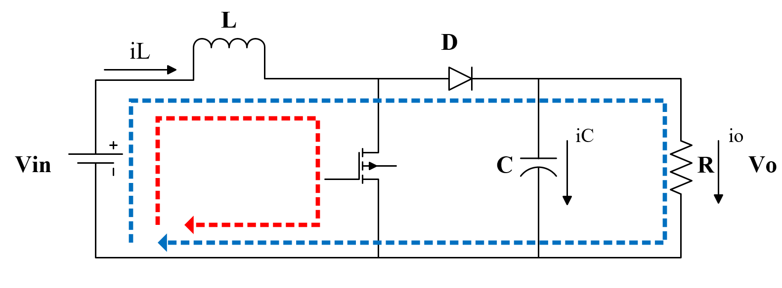
The boost converter has two operating modes, as shown in Fig. 1. When the switch is in the ON position (red line), the circuit consists of the input voltage and the inductor. In this mode, the inductor stores energy in the form of electric current. The longer the switch is closed, the larger the current stored in the inductor. When the switch is in the OFF state, the stored current in the inductor flows directly to the diode and the capacitor (blue line). As a result, the capacitor voltage becomes higher than the input voltage.
In the ON state of the switch, the following dynamic model will be obtained:
| (1) |
| (2) |
Meanwhile, in the OFF state of the switch, the following dynamic model will be obtained:
| (3) |
| (4) |
where  represents the inductor current,
  represents the capacitor voltage,
  is the input voltage,
  is the output vector, and
  ,
,  ,
,  are resistance, inductance, and capacitance respectively.
By combining both switching conditions with the assumption that  = duty cycle during ON state and
  = duty cycle during OFF state, the following equations are obtained:
| (5) |
The state-space model of the boost converter, obtained by substituting the ON and OFF state equations, is as follows:
| (6) |
| (7) |
| (8) |
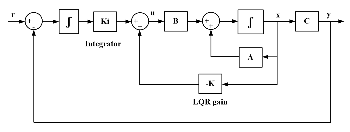
In principle, LQI is an extension of the LQR controller with the addition of an integrator. LQI is compatible to use for servo control system (system with a non-zero set-point). LQI utilizes optimal control that allows for reference signal tracking and disturbance rejection. The block diagram of the LQI controller is shown in Fig. 2. In the block diagram, there are matrices  ,
,  , and , which represent the linear model of the plant to be controlled, also
  and
and  as the controller and the integrator gain.
In the control of the boost converter, the state variables used  . With the addition of the integral action, an additional state is introduced, which is the error (
 ). As a result, the matrices , , and of the plant to be controlled become:
| (9) |
Thus, the control signal () generated from the model satisfies:
| (10) |
where is the LQR gain and is the integrator gain. In this study, the controller gain is obtained using LQI MATLAB function based on , , ,  , and matrices. , , and matrices is generated from the state-space average model of the converter, while the and matrices are determined by intuition. In the LQI method, the dynamic system must have controllability criteria. To find out this criterion, it can be tested using the following equation:
| (11) |
where  is controllability matrices, and are matrices from equation (9) respectively. The system is controllable if the matrices have rank
  . Then, and matrices are weighting value to minimize error and control signal based on this cost function (
 ) below:
| (12) |
This cost function aims to minimize the state vector  which consists of
  ,
,  , and by using the matrices, while the control signal is minimized using the weight matrix .
In this study, the boost converter is implemented using the parameters as shown in Table 1.
Parameters | Value |
Input Voltage (Vin) | 10-12 V |
Inductor (L) | 15 µH |
Capacitor (C) | 3125 µF |
Resistor (R) | 20 Ω |
Switching Frequency | 40 KHz |
In the search for the LQI controller gains, the matrices , , , , and are needed. The matrices , , and are obtained by substituting the parameters from Table 1 into equation (9), resulting in the following:
| (13) |
Based on the controllability test result, rank  . Thus, the system can be controlled. For the determination of matrices Q and R, an intuition approach is used. In this study, since the objective is to minimize , the weight matrix Q is chosen to be 10 times larger than the weight matrix R. By using MATLAB with the LQI function, the control parameters are obtained as shown in Table 2.
Q | R | K1 | K2 | Ki |
| 1 | 0.3788 | 0.0846 | 25 |
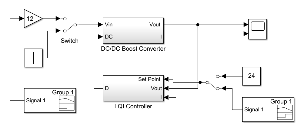
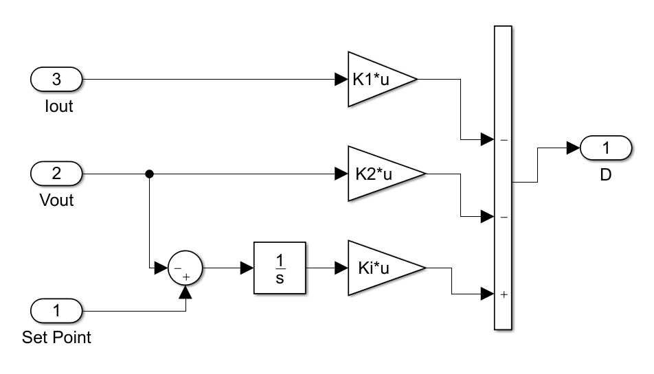
In the simulation testing, this system utilizes the MATLAB/Simulink application. The model used for the simulation is shown in Fig. 3, with LQI controller subsystems as depicted in Fig. 4.
In the MATLAB simulation, the boost converter acts as the plant and its duty cycle is the control signal. The LQI controller will generate the duty cycle to achieve the desired output voltage.
In the MATLAB simulation, two testing scenarios are conducted. The scenarios are input change testing and load change testing.
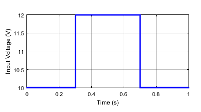
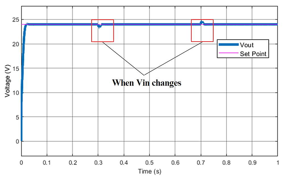
The simulation in the input change testing scenario is conducted to observe the control performance when the input voltage is not constant. The input voltage is changed by adjusting it from 12 V to 10 V and then back to 12 V as shown in Fig. 5. The simulation is carried out with a set point of 24 V.
Fig. 6 shows that the LQI controller can maintain the voltage at the set point of 24 V. When the input voltage is changed, the controller quickly stabilizes the voltage back to 24 V, as indicated at 0.3 s and 0.7 s. Based on the analysis, the settling time obtained is 0.06 seconds and the Integral Absolute Error (IAE) is 0.1205. These results demonstrate the effectiveness of the LQI controller in achieving fast response and small error when there is a change in input voltage.
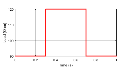
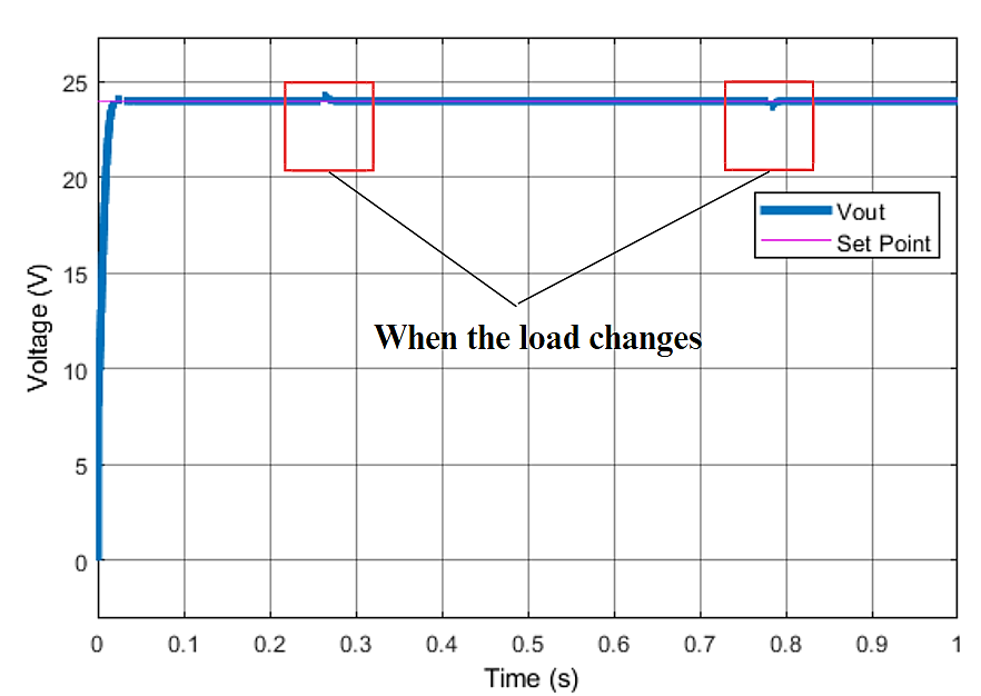
The second simulation test with the load change condition is conducted to observe the control performance when the load is not constant. The load variation is achieved by using resistance of 90 Ω and 120 Ω, as shown in Fig. 7. The simulation is carried out with a constant input voltage of 12 V and a set point of 24 V.
Fig. 8 demonstrates that the LQI controller can stabilize the output voltage at 24 V even under load variations. The voltage response results in a settling time of 0.02 s and an IAE value of 0.1143. These findings indicate that the LQI controller effectively maintains the desired output voltage despite changes in the load, providing fast response, and produces small error.
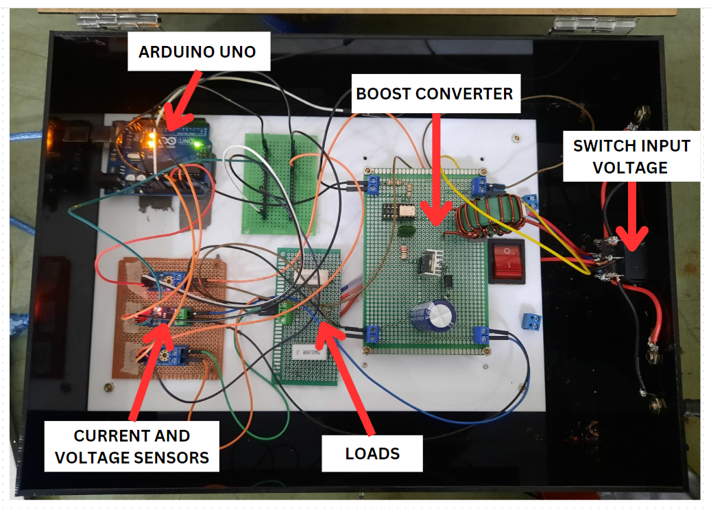
The hardware realization of the DC-DC boost converter control system can be seen in Fig. 9. The DC input voltage is connected to the boost converter circuit. Then, voltage and current sensors are used to measure the state variables of the boost converter. The output from these sensors is converted into 10-bit ADC values, which will be read by the Arduino Uno microcontroller. In this board, the LQI controller is embedded and will generate the PWM signal to drive the MOSFET in the boost converter circuit.
The experimental testing is carried out using the control parameters that have been determined from the MATLAB simulation. The controller gain used in the hardware experiment is the same as those used in the simulation with slight tuning. The LQI method is implemented in the programming language and embedded in the Arduino Uno microcontroller.
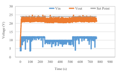
Likewise in the simulation, the first hardware experiment was carried out for a changing input voltage. The load set on 90 Ω with set point of 24 V. The input voltage is varied between 12 V and 10 V. The experimental results are shown in Fig. 10.
Based on the input change testing results, it can be observed that the output voltage response remains stable at 24 V, even with changes in the input voltage at seconds 2.4 and 5.4. When the input voltage is lowered, there is a slight decrease in the output voltage value generated by the boost converter, but it still remains close to the set point. Despite maintaining a stable output voltage close to the set point, there is still a steady-state error of 9.24%.
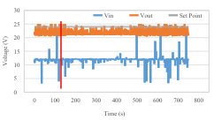
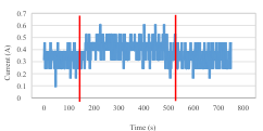
The second experiment is conducted on the hardware setup with an input voltage of 12 V and a set point of 24 V. The load is changed between 90 Ω and 220 Ω. The results of the voltage control can be seen in Fig. 11 and the current response due to load profile changes is shown in Fig. 12.
Based on the second experimental results, it can be seen that the output voltage remains stable at 24 V, even with changes in the load at seconds 1.6 and 4.9. When the load resistance is modified, there is no significant change in the output voltage. Similar to the previous scenario, in this case, there is still a steady-state error of 8.21%. The steady-state error indicates the difference between the desired output voltage and the actual output voltage. This condition may occur due to limitations in the switching specifications of the MOSFET devices used.
The voltage stability control of the boost converter using the LQI controller has been successfully carried out. By setting the Q matrices 10 times higher than R matrices, the output voltage response for the two disturbance scenarios is resulted an IAE value less than 0.2. In the simple hardware experimental testing, a good voltage response is also produced with a steady-state error less than 9.5%. However, in this study it has not been considered to minimize the control signal by increasing the value of the R matric. Further research can be conducted to develop the controller by considering the optimization of the control signal and enhancing the specification of the hardware used.
The author would like to convey appreciation to Politeknik Negeri Bandung for the financial funding provided for this research.
Nurul Fitri Muthmainnah, Voltage Stability Control of Boost Converter Using Linear Quadratic Integrator