Journal of Fuzzy Systems and Control, Vol. 1, No 2, 2023 |
Analysis of a Self-excited Induction Generator with Fuzzy PI Controller for Supporting Domestic Loads in a Microgrid
Arunava Chatterjee
Department of Electrical Engineering, Raghunathpur Government Polytechnic, Purulia, India
Email: arunava7.ju@gmail.com
Abstract—This study provides a technical analysis of integrating a microgrid structure for power generation with a wind energy conversion system. This study's primary objective is to identify solutions to issues that arise when isolated induction generator is utilized in a microgrid. A closed loop electronic load connector is used to control the loads of the induction generator-based system. The load controller is adjusted using an adaptive fuzzy based proportional-integral (PI) controller for better control. Additionally, by employing a straightforward variable capacitor design to inject reactive power during voltage dips, it provides a way to sustain the voltage profile. The suggested approach and its control are investigated in MATLAB/Simulink and verified with the aid of a laboratory experimental setup. The outcomes clearly demonstrate the practicality of the suggested plan to be implemented in grid-isolated places.
Keywords—Electronic Load Connector, Fuzzy PI Controller, Induction Generator, Variable Excitation, Wind Power
These days, burning fossil fuels like coal, oil, and natural gas produces the bulk of the energy needed to produce electricity. The supply of these fossil fuels is limited, and their combustion results in the emission of a sizable amount of poisonous gases into the environment. Finding sustainable and clean sources of energy is thus constantly required. A clean, unlimited renewable energy source is wind [1]. There are various ways to convert wind energy into electrical energy, but by far the most popular technique is to use a wind turbine. Theoretically, any generator may be mounted on top of a wind turbine to generate power. The need for grid-compatible electric current may exist even if the generator only generates direct current or alternating current with variable amplitude and frequency and it can currently be satisfied by connecting the appropriate converters.
The induction generator (IG) appears to be a great choice for many applications because of its durability, low maintenance needs, and simple controls [2]. Since its simplicity of use, durability, and small size per generated kilowatt, IG is recommended for production of wind energy. Moreover, the excitation magnetic field generated by IGs may be produced without the use of an external power source. As a result, they may be used in remote and desolate areas [3]-[5]. Although the development of static power converters has made it simpler to manage the output voltage of IGs, reactive power consumption and poor voltage regulation at variable speeds continue to be the primary drawbacks of IGs [6].
Since it does not need an extra power source to generate the magnetic field, the self-excited induction generator (SEIG) is a fantastic choice for wind-driven electric generation applications, particularly in places with variable wind speed and isolation. Although the SEIG scheme was created over 80 years ago, a significant number of research publications have recently started to focus more on the analysis of and applications for SEIGs [7]-[8]. This is a result of improved voltage and frequency control techniques as well as the increased global focus on the advancement of renewable energy sources during the last thirty years.
The main operational problem with the SEIG system is its inability to control voltage and frequency under fluctuating load conditions. A change in the load impedance has an instantaneous effect on the machine excitation. This is due to the fact that the reactive power of the excitation capacitors is shared by the induction machine serving as the generator and the load impedance. The generator's voltage therefore decreases as the load impedance rises, resulting in poor voltage management. The slip of the induction generator, on the other hand, increases with increasing load despite the fact that the speed of the prime mover remains constant, leading to a frequency that is dependent on the load. To control the voltage and frequency of a SEIG system working with fluctuating loads, several researches have been done in the past.
A typical traditional SEIG controller is a high-priced speed governor. According to [9], a sliding mode controller was presented, demonstrating regulated dynamic response and behavior of the system in response to changes in generator characteristics and load. A SEIG's voltage and frequency regulation under different load circumstances is investigated using an electronic load controller [10]. The voltage control issue is partially handled with the use of static converters; however, the system cost is significantly raised [11]-[12]. Control methods based on maximum power point tracking (MPPT) are also often used.
Grid-connected generation may be operated more easily with the help of MPPT techniques [13], nevertheless, standalone grid-secluded generation is usually managed without MPPT to lessen system complexity [14]. However, as independent generations are regularly used to carry out significant tasks, keeping a steady generation becomes essential [15].
However, the regulation of speed and voltage does not always result in a performance level that is always adequate due to the machine's severe dynamic slip changes and the difficulties of developing a smooth variable reactive power supply at an affordable price.
In order to help with the resolution of the aforementioned operational challenges, this research comprises a technical analysis of the IG system when feeding varied home loads with a specialized fuzzy controlled load controller. The intended study suggests a dynamic capacitor-based voltage regulation method that has the potential to deliver changeable reactive power for the IG powering grid-isolated loads during load and speed transients. A suggested capacitor switching system based on a microcontroller is also demonstrated to improve the transient responsiveness. To continuously power grid-isolated loads, the IG-based structure may subsequently be linked to other renewable energy generators.
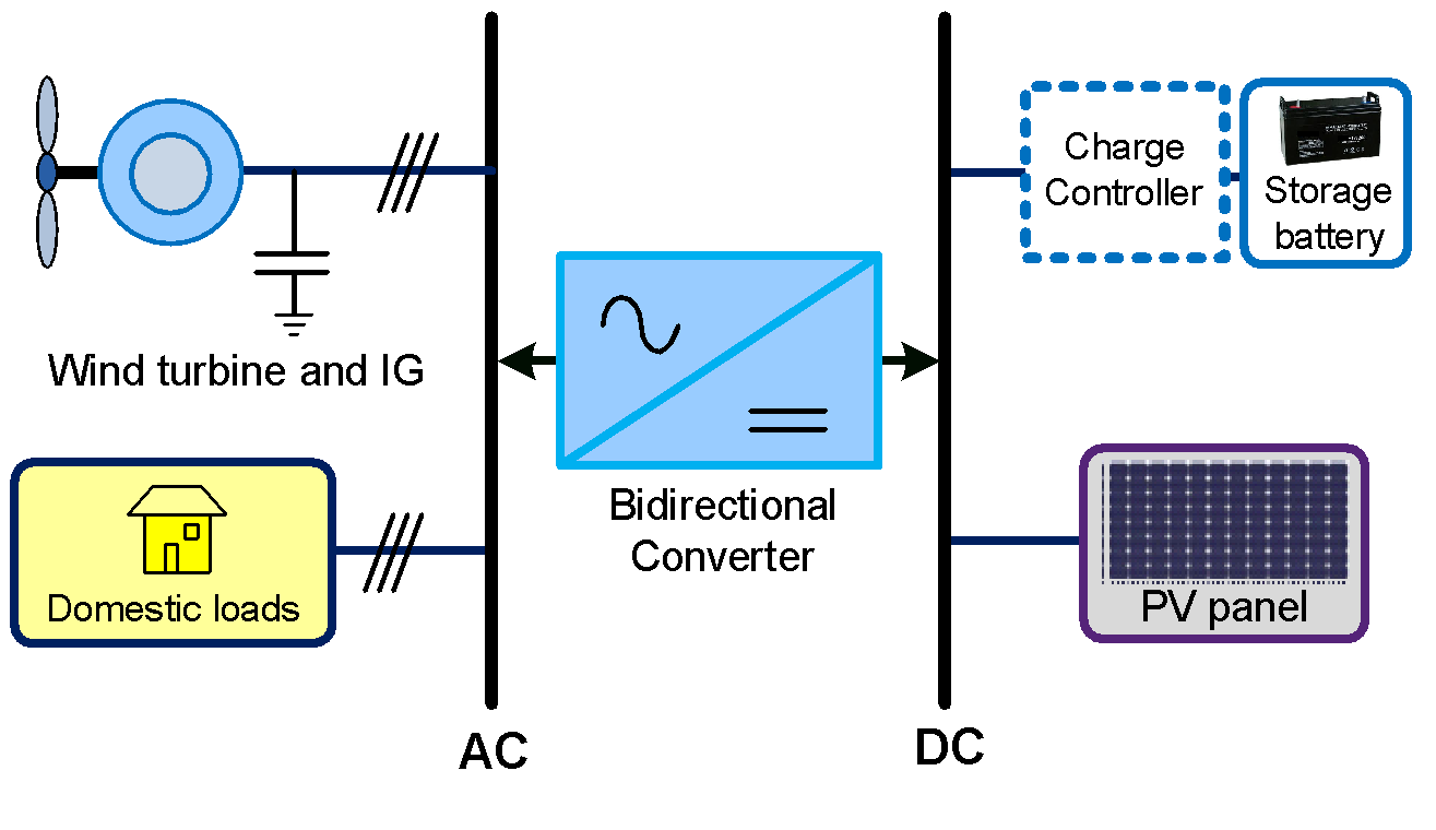
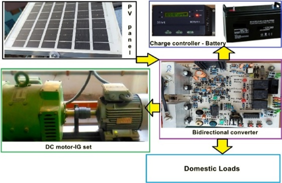
A three-phase induction machine that is coupled to a wind turbine serves as the basis of the proposed generation system. The IG is linked to a bus where supply connections for system loads are also possible. The induction machine's stator windings are connected to a capacitor bank to provide the initial reactive power. Reactive power balancing is used to determine the initial excitation [16]. The IG system may also be coupled to a standby PV panel for boosting and sustaining generation. Additionally linked through a charge controller is a storage battery that will supply the loads during times of low power production. Fig. 1 depicts the integrated system.
The suggested system is designed for usage in an onshore, eastern Indian site that is grid-isolated. Since there is no grid connection at the location, the usefulness of the proposed generating plan is crucial in providing electricity to the loads that are linked remotely. The bidirectional converter assists in sending active power and reactive power to the load and IG while it can also send back power to the battery during surplus generation from the IG.
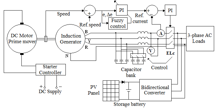
The IG is used to offer the suggested system generation. A photovoltaic (PV) panel is also connected to the IG. The microgrid structure with PV panels is not shown for the proposed IG control. With varying wind speeds and variable loads, the control is primarily concentrated on the IG side control of the electronic load connector (ELc) and the variable capacitor bank control. In Fig. 2, the generation and control system are displayed.
The shaft speed of the IG linked to the prime mover is noted for the proposed control, and the data is passed to a comparator circuit. A fuzzy controlled proportional-integral controller (PI) similar to fuzzy-PID [17]-[18] receives the set error and the change in error value. After comparison of the shaft speed the reference speed, the signal is sent to fuzzify and further modify the PI controller gains. The output from the fuzzy PI controller is used as the reference current, and the system load current is compared with it. Following this method, pulses are created to control the ELc. The well-known Ziegler-Nichols tuning method is used to adjust and tune the second PI controller. For the fuzzy PI controller, the error is calculated as,
| (1) |
Where, e1 is the error from reference speed ω* and measured speed of shaft ωm at an instant n. The change in error is given as,
| (2) |
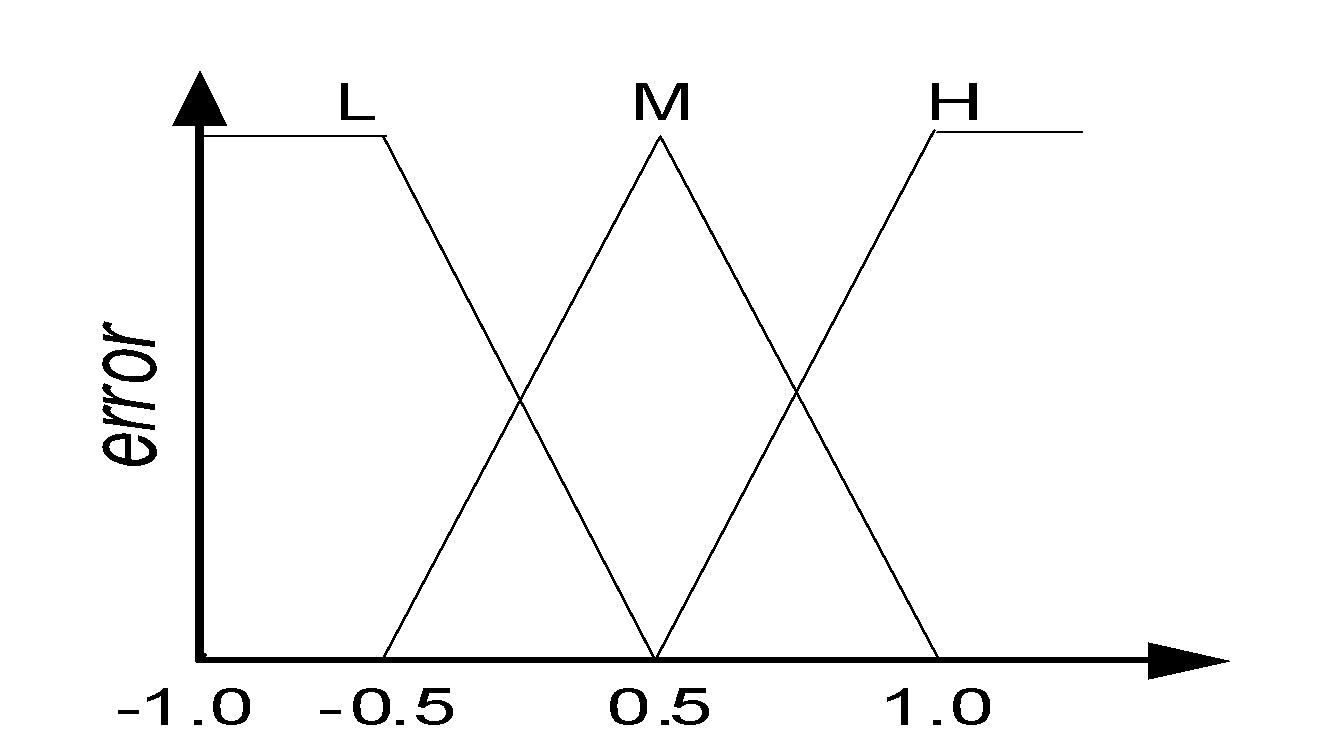
Where, e1[n-1] is the is the value of the previous error. Fuzzy normalization of the set is done and denormalization is made at output. The defuzzifier method must translate the fuzzy values acquired from fuzzy inference into output crisp values. The fuzzy triangle membership functions are defined for this with three clusters for each input.
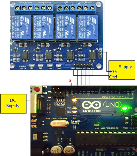
The benefit of using speed reference is that it can manage and make use of the lower ranges of wind speeds, which are frequently disregarded for wind generation. Depending on the situation, additional capacitors are used for regulating load and speed factors. The ELc is controlled using ARDUINO UNO controller board.
At first, the system is simulated in MATLAB/Simulink. The IG system is simulated using a three-phase induction machine model build using the stator reference frame equations [19]. The three-phase induction machine working as generator has a rating of 1.5 kW with 415V, 50Hz, and is wound for four stator poles. The computed model and the experimental prototype both has comparable ratings. The simulated model also uses the suggested control. The hardware implementation is split into two phases. First, a laboratory prototype is used to validate the simulation findings. Second, for the suggested IG, an electronic load connector and variable excitation connector were created. Table 1 shows the hardware setup system com ponent details.
Sl. No. | Component | Rating and details |
1 | Induction Generator | 3-ph., 1.5kW, 415V, 50Hz, 4-poles with 36uF capacitor bank |
2 | DC motor prime mover | Shunt wound, 2kW, 400V |
3 | Converter | 2kW, MOSFET used K2611 (900V, 11A) |
4 | PV panel | Polycrystalline Silicon, 500W x 2, 48.6V |
5 | Storage battery | Lead acid, deep cycle, 12V, 100Ah x 2 in series |
(a)
(b)
(a)
(b)
However, at this pace, the frequency of the produced voltage is less than standard 50Hz and therefore the bidirectional converter is operated at load end at fixed frequency of 50Hz.
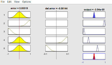
Along with components in Table 1, an ARDUINO UNO based controller and modular static relay modules are used for controlling the loads and capacitors. The fuzzy PI controller is realized using the same controller. The fuzzy simulated logic rule viewer simulation in MATLAB/Simulink for error and change in error along with the output is shown in Fig. 3. The error membership is also shown and for the same figure, the scale of change in error will be multiplied by 0.1.
Terminal loads can be connected across the generator's stator windings once it has reached a steady condition. A DC machine is connected to an induction machine in the experimental setup depicted in Fig. 4. The prime mover is the DC machine. With few adjustments, the DC machine is utilized to match the characteristics of a wind turbine.
However, given that various gears may be employed in actual operation with the wind turbine to generate at rated speed for the IG, it is assumed that the prime mover drives the generator at rated speed. The mechanical contacts of the laboratory-based experimental IG were shown to be capable of repeated usage. A digital contactor switch was required because of mechanical wear and tear. The variable capacitors and loads were connected with an ARDUINO UNO-based switch. Relay switches that are electronic are used for this. The circuit is more effective when used for various loading circumstances and wind speed conditions thanks to the connection of the relay coil for switching loads and capacitances.
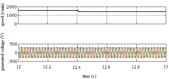
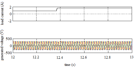
Fig. 5 shows the simulated voltage when there is a change in speed from 1500 rpm to 1400 rpm. The fluctuation in IG voltage caused by the suggested regulation is then observed. With a load shift from half rated to rated load current (rms value), it is seen that the produced voltage varies very little. This is seen in Fig. 6.
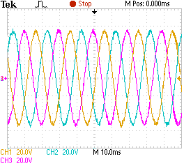
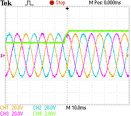
Additionally seen are the experimental waveforms for the suggested method. Fig. 7 (a) and Fig. 7 (b), demonstrate the produced voltage profile and corresponding step changes in load from 0.5 p.u. to 1 p.u. and system voltage. The readings are taken using a 100MHz, four-channel digital storage oscilloscope. For Fig. 7 (a), each channel is rated at 150 V/division and for Fig. 7 (b), channels 1, 2 and 3 are rated at 200V/division and channel 4 is rated at 0.5 p.u. current/division.
As noted, the generated voltage could be maintained well with such step change in system load. The system voltage could be maintained well even when there is a considerable increase in load current. The voltage is maintained with increase in momentary system capacitor switching using the proposed controller.
(a)
(b)
It is noted that there is good agreement between the simulation and the experimental results. Experimental observations of the electronic load connector switching transients are also studied.
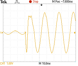
Fig. 8 displays the measured waveform of the ELc phase voltage when there is a requirement of increase in capacitor with increase in load. The observed voltage regulation is superior than the majority of traditional control strategies.
A technical analysis of wind energy conversion integration with microgrid architecture for power generation is presented in this study. The major aim of this study is to identify issues that arise when isolated IG is utilized in a microgrid. Using an electronic load connection with capacitive control, it also provides a way to maintain the voltage profile by supplying reactive power during voltage dips. The MATLAB/Simulink environment simulations and a laboratory experimental prototype are used to study the characteristics of IG and its suggested regulation. Analysis has been done on IG control method.
Future improvements to the induction generator's design processes and more optimizations can be made to enhance its performance. Similar systems can be used in isolated load generation and smart management [20] or home energy management [21] such as using internet of things.
20
Arunava Chatterjee, Analysis of Self-excited Induction Generator with Fuzzy PI for Supporting Domestic Loads in Microgrid