Journal of Fuzzy Systems and Control, Vol. 1, No 2, 2023 |
Smart DC to DC Converter for a Small Drone Based Deep Learning Technique
Mays Abbas Al-bahrany 1, Ahmad T. Abdul Sadda 2,*
1,2 AL Furat Al Awast Technical University, Al Najaf 540001, Iraq
Email: 1 eng.mais.ece@gmail.com, 2 coj.abdulsad@atu.edu.iq
*Corresponding Author
Abstract - Flying a small robot like a drone needs more conservative energy, small solar cell size needs to robust efficient DC-to-DC converter. Mathematical analysis for finding the optimal duty cycle in the PWM (pulse width modulation) is presented at different supplies voltage, considering a low voltage of 8 volts for low-speed motor rotation speed and 18 volts for high speed of the rotation motor. The dc-dc converter gets the power desired from the small robotic by using a dc-dc buck-boost converter. The Proportional Integral Derivative (PID) control, smart tuning different rules fuzzy logic control, and a hybrid fuzzy-PID controller as one solution for dc-dc converter control. The controller must be capable of processing the desired value of the output voltage of the dc-dc converter.
Keywords - Buck-Boost Converter, PID, Fuzzy logic Control, Hybrid fuzzy-PID Controller.
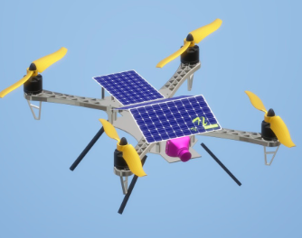
Recently, small drones took place in many applications, especially in the military and the healthy and humane being easy life techniques. One of the ideas is to create and fabricate small robotic vehicles capable of flying without being tethered to an external power source. The hard part was building something that could produce enough thrust while still being light enough to fly as shown in Fig. 1.
“The study's major goal is to develop and put into use a DC/DC converter with a fuzzy logic controller for solar energy harvesting. The integration of a microcontroller to monitor the battery's level of charge are the specific goals of this research. The DC/DC converters are well known in unconventional sources and are also widely used in fields like medicine, physics, and the military, among others. In general, boost converters are in high demand in situations where a high dc voltage is needed [1]. This paper discusses many methods for attaining high gains than typically obtained by boost converters based on these requirements.
The electrical power magnitude is increased by unconventional energy sources. Power converter topologies are particularly helpful for the next stage of power generation since solid fuel produces pollutants. The output voltage of the PV panels ranges from 20 to 60 volts. The DC/DC boost converters are frequently used for connecting PV panels and inverter-load combinations. For voltage gain in PV panels, a large boost-up is needed. About 380 volts are required for the input of a full bridge inverter [2]-[3].
To proceed with the system's stability, Mukherjee et al. [4] conducted a series of connections in a DC/DC topology. The cascaded converters have often been separated into three separate literary examples: some types of sources, such as batteries [5]-[10]. Various sources are used in converters, such as fuel cells, and supercapacitors [11]-[12], standalone photovoltaic systems with batteries or solar/wind hybrid energy systems [13]-[16]. Variable operating conditions at the same type of sources in converters. The variables may include photovoltaic panels that are partially shaded in different ways [17]-[18].
For an input series output series (ISOS) converter to achieve input voltage sharing (IVS) and output voltage sharing (OVS), Wei et al. [19] introduced the duty cycle-based model predictive control (DCMPC) technique. They also put forth a discrete-time optimized model of an input series output series type converter, and the cost function is used to estimate the optimal duty cycles for input voltage sharing and output voltage sharing. Comparing the suggested method to the traditional proportional-integral (PI) controller-based method. Due to its simplicity, low cost, and superior dynamic performance, the suggested duty cycle based MPC technique is superior for input voltage sharing and output voltage sharing, according to the comparison of the result [20].
The conventional bidirectional buck-boost converter is non-isolated, inexpensive, and of straightforward design. A topology made up of a linked inductor and a bidirectional buck-boost converter was proposed by Chen et al. [21]. The family of soft-switching bidirectional converters with a high ZVS range was proposed by Mohammadi et al. [22]. Bidirectional dc-dc converters that are not isolated have been covered in [23]-[24] through [25]. An innovative method that reduces ripple current while operating at the battery side in the high current range was proposed by Bahrami. H [26] et al.
The voltage source converter-based high voltage direct current system is becoming more significant as the HVDC system gains popularity. When compared to thyristor-based HVDC systems, voltage source converter-based HVDC has more advantages. It has a high output voltage and current with no ripple, a converter with a black start, active and reactive power regulation, and these features. These converters also have several drawbacks, including as switching losses and a reduced ability to withstand dc side faults. Certain multilevel converters have been introduced to help solve all of these issues [27]-[33].
This study is important because it will serve as the foundation for all future research on DC-DC converters used with renewable energy sources, notably solar energy. Finally, this research will add to our knowledge of the applications of DC-DC converters and fuzzy logic controllers. It will also serve as a benchmark for any future research on buck-boost DC-DC converters.
The goal of the study is to incorporate a fuzzy logic controller and buck-boost converter to produce a solar charging system. To apply buck and boost input voltage, the solar panel's 10 W rating and the batteries' 8 V, and 18 V ratings were used. The fuzzy logic controller made use of a triangular membership function. However, the circuit was not designed with overcurrent protection, overvoltage protection, overtemperature protection, or maximum power tracking”.
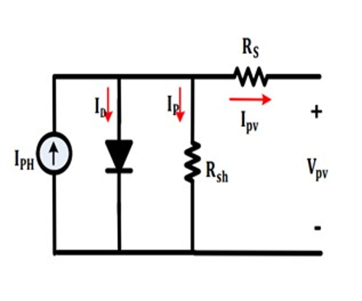
The most promising technology to produce electrical energy is photovoltaic cells, which over the past few years have shown the greatest development compared to other types of renewable energy sources. The main problems with photovoltaic systems are the relatively low efficiency of energy conversion and the apparent dependence of the energy characteristics of solar cells on climatic conditions. To increase energy conversion efficiency, most modern photovoltaic systems are designed using maximum power point tracking technology, which allows for increased electrical power generation, the main schematic diagram shown in Fig. 2.
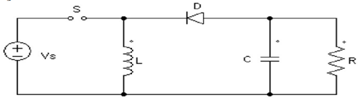
The Maximum Power Point Tracking (MPPT) technology is based on three main components: the MPPT method, the MPPT controller, and the DC-DC converter. The purpose of the research is to design a methodology for selecting the parameters of the basic components of MPPT technology and obtaining high power conversion efficiency. A topology buck-boost converter is shown in Fig. 3.
Inductor (L), diode (D), filter capacitor (C), load resistance (R), controlled switch (S), and dc input voltage source VS make up the converter. When the switch is turned on, the diode is reverse biased and the inductor current rises. The diode acts as a channel for the inductor current when the switch is off, which is how the buck-boost's DC voltage transfer function works. Regarding ground, the output voltage V0 is negative. As implied by the converter's name, its magnitude can be either higher or lower (equal at D = 0.5) than the input voltage.
| (1) |
In this paper, we designed and simulated a PID controller, a Fuzzy logic controller, and a hybrid FUZZY PID control system as shown in Fig. 4 to stabilize the output voltage of the buck-boost converter.
The output voltage of the DC/DC buck-boost converter is managed by the PID controller. To achieve the necessary step response for the system, a PID controller is used to decrease tracking error in the system. The parameters are typically fixed during an operation and are known as Kp, Kd, and Ki. As a result, the PID controller is ineffective for regulating a system when its surroundings are changing. The PID controller's fundamental equation is (2).
| (2) |
Where e[n] and e[n-1] are the error value and the difference error of the output voltage concerning the reference voltage, respectively. The rule to tune the parameters is based on Table 1.
Parameter | Speed of Response | Stabiity | Accuracy of the Output |
Increasing Kp | Increases | Deteriorates | Improves |
Increasing Ki | Decreases | Deteriorates | Improves |
Increasing Kd | Increases | Improves | No Impact |
A thorough understanding of the system's operation is necessary for the construction of a fuzzy controller. The aim of the designer is to ensure that the output voltage matches the reference voltage, which is indicated in the many processes involved in the design of fuzzy controllers for power converters. The voltage error (e) (reference voltage subtracted from real voltage) and the change of the voltage error (de) (prior error subtracted from current error) are the inputs to the fuzzy controller.
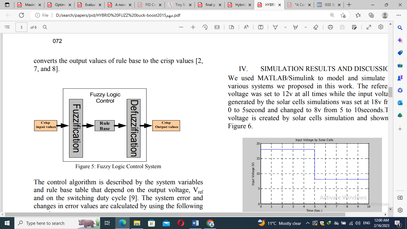
The membership functions of a fuzzy set serve as indicators of its fuzziness. Whether the element in the set is discrete or continuous, it is classified. Graphical representations can also be used to create the membership functions. Different shapes could be present in the graphical representations. There are several limitations on the forms that can be used. Fuzzy rules are developed to express fuzziness in an application. One crucial factor that needs to be taken into account is the structure of the membership function. In Fig. 5, the fuzzy logic procedure is displayed.
Despite having a quick dynamic response, the fuzzy logic control technique has a steady-state error that is not zero. As a result, we had to merge our fuzzy system with a PID controller, creating a hybrid system. The drawbacks of using only fuzzy logic control are eliminated by the PID controller. Like how the PID controller's drawbacks, including its increased overshoot and undershoot, are corrected by the fuzzy logic controller.
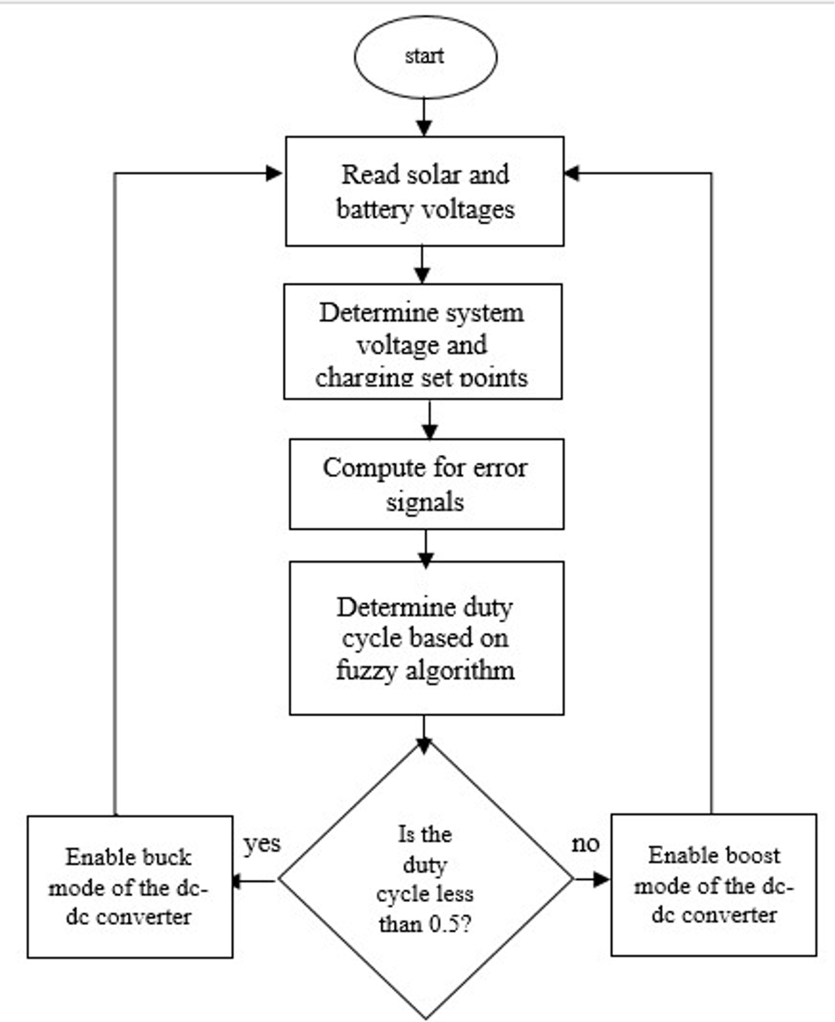
Fig. 6 shows the flowchart for the program. The battery that needs to be charged is first measured by the program. The microcontroller will set the target output voltage of the converter following the detection process. By comparing the reference voltage with the solar panel voltage picked up by the sensor, the error will be computed. The fuzzy controller will receive its input from the error signals. Based on the error signals and the fuzzy rules, the fuzzy controller will determine the duty cycle. After determining the required duty cycle, the system will select whether to buck or boost the input voltage generated by the solar panel.
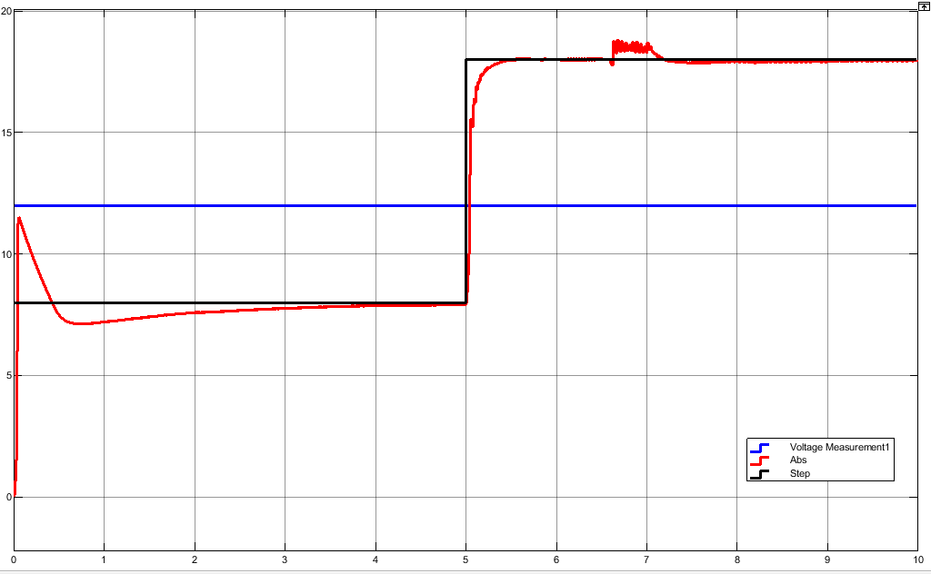
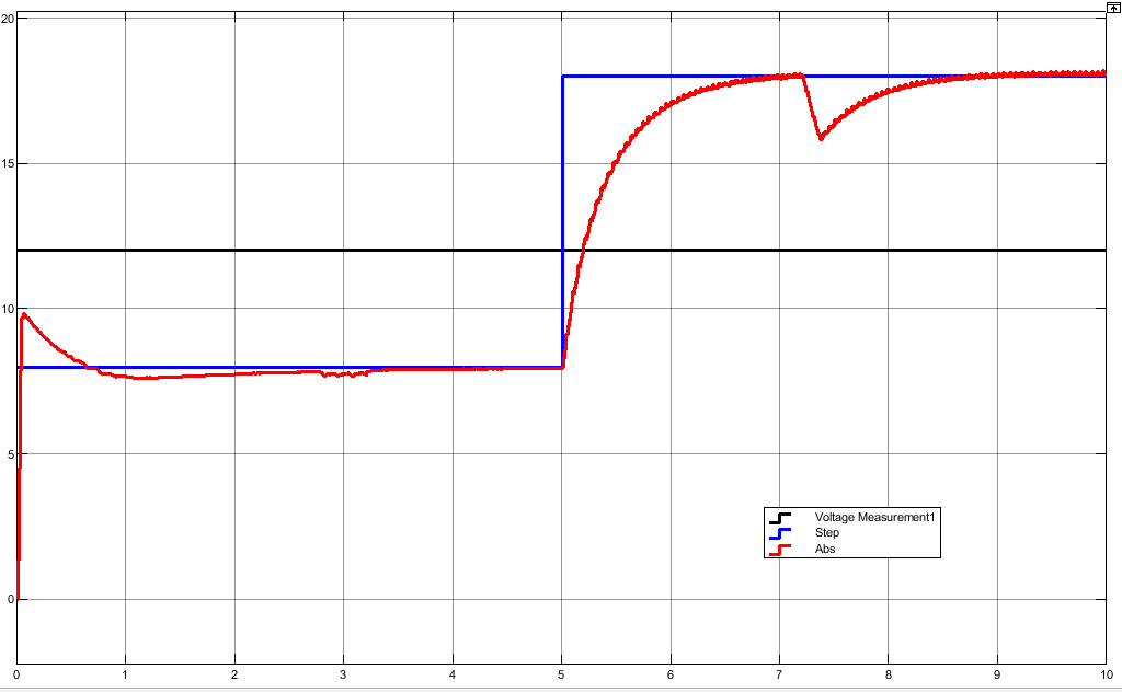
To simulate and model different systems, we used MATLAB/Simulink. While the input voltage produced by the solar cell simulation was set to 18 volts from 0 to 5 seconds and changed to 8 volts created by solar cells, our proposal called for an output voltage that was always set at 12 volts. The filter inductance of the DC/DC buck-boost converter is equal to 1.33 mH, the filter capacitance is equivalent to 100.67 m F, and the output resistance is equal to 10 Ω.
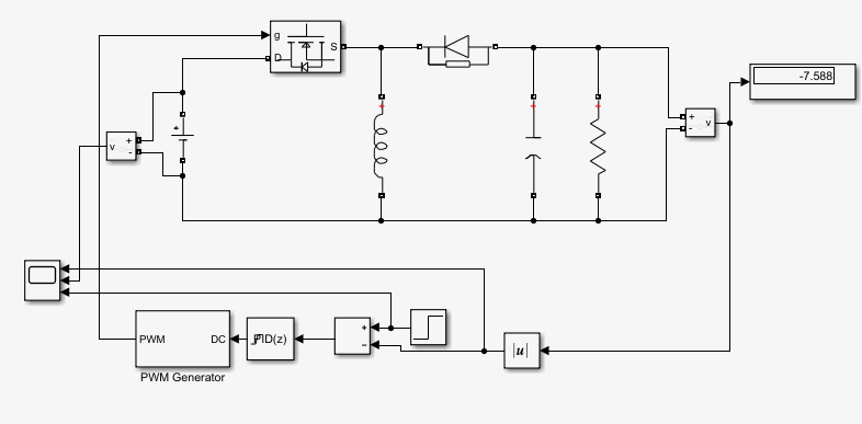
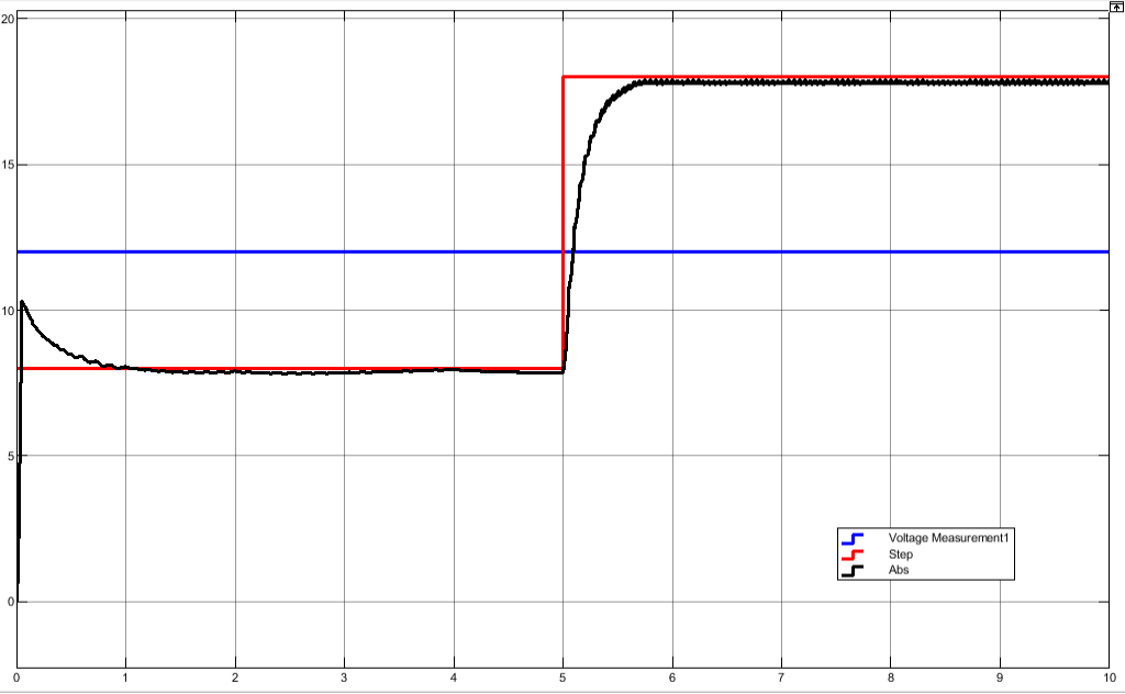
Here we considered the Buck-boost converter with traditional PID control, and the value of the parameters gains that are considered by using the trial-and-error method; (Kp=0.5, Ki=0.3, and Kd=0.05). Fig. 7 shows the simulation Simulink MATLAB circuit design and the simulation results.
a) Circuit design |
b) Simulation result when L= 1.33 mH |
c) Simulation result when L= 10 mH at T=6.5s |
|
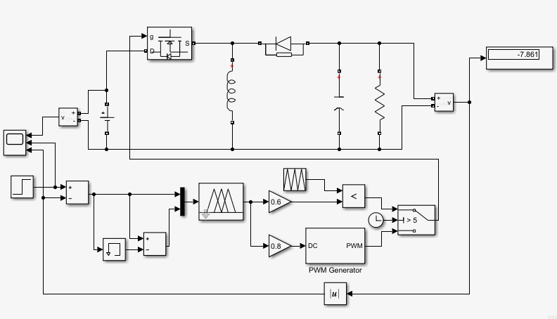
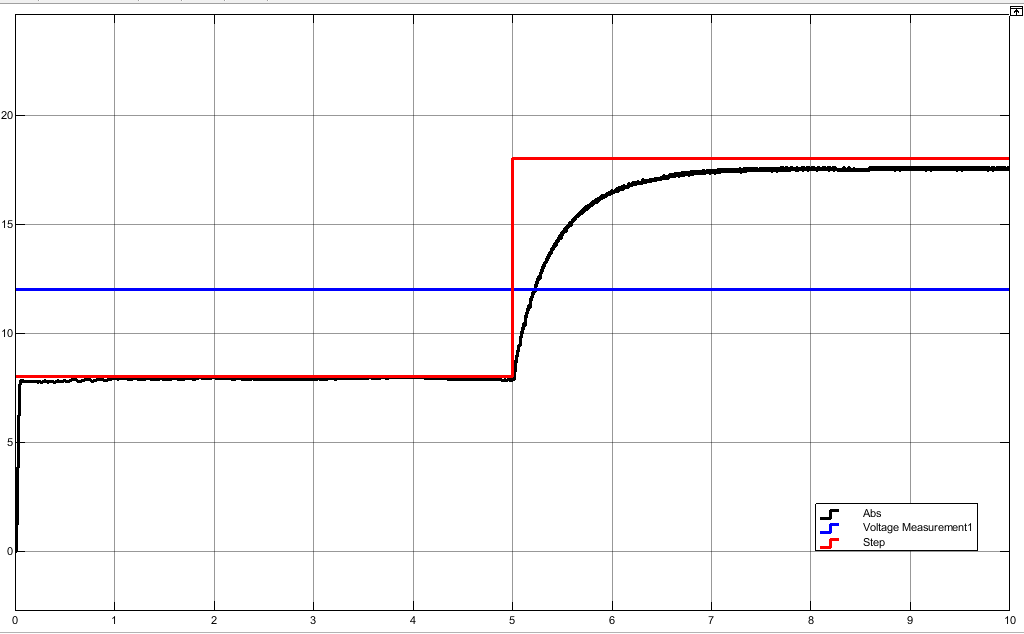
Here we considered the Buck-boost converter with fuzzy logic controller. Fig. 8 shows the simulation Simulink MATLAB circuit design and the simulation results.
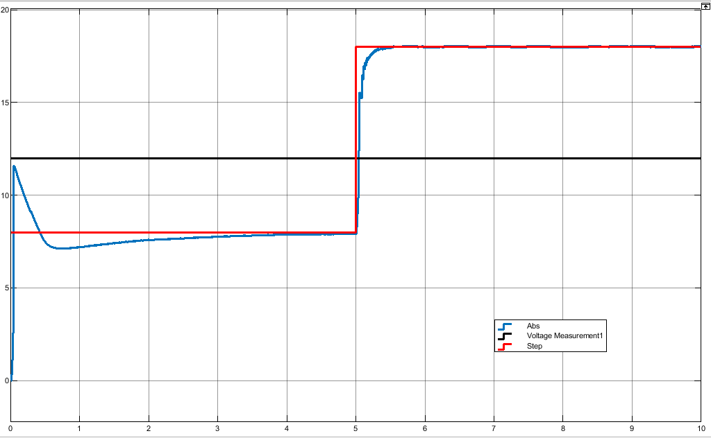
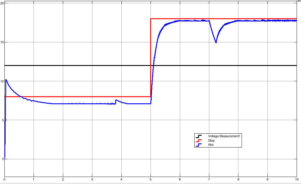
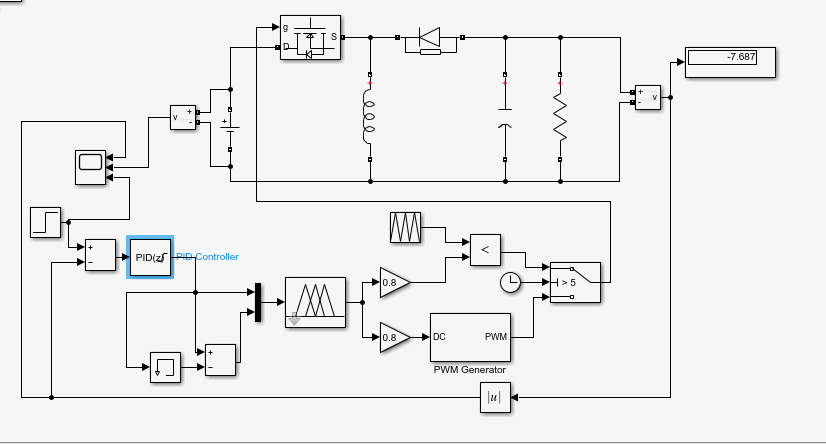
Here we considered the Buck-boost converter with a hybrid Fuzzy-PID logic controller. Fig. 9 shows the simulation Simulink MATLAB circuit design and the simulation results.
a) Circuit design |
b) Simulation result when L= 1.33 mH |
c) Simulation result when L= 10 mH at T=3.8s & T=7s. |
|
a) circuit design
b) simulation result when L= 1.33 mH
c) simulation result when L= 10 mH at T=3s & T=7.5s.
The output voltage does not significantly overshoot, and no parameter changes are required to stabilize the system. In Figure 9 (b), the simulation FLC results and simulation PID results are contrasted. The FLC reaction time is faster than the PID simulation response time. However, compared to FLC, the PID controller exhibits more oscillation and overshoot. Compared to PID and FLC controllers, the hybrid Fuzzy-PID controller's findings are more clearly shown. As shown in the Table 2.
Output voltage = 8 V (buck mode) | |||
Settling Time | Rise Time | Overshoot (%) | |
PID | 4s | 0.4s | 37.5 |
FUZZY | 1s | 1s | 25 |
HYBRID | 0 | 0.1s | 0 |
Output voltage = 18 V (boost mode) | |||
Settling Time | Rise Time | Overshoot (%) | |
PID | 0.5s | 0.5s | 0 |
FUZZY | 0.7s | 0.7s | 0 |
HYBRID | 2s | 2s | 0 |
The researchers succeeded in achieving the study's goals. For capturing solar energy, a DC/DC Buck-Boost converter with the fuzzy logic controller was used. We created and built a PV cell buck-boost converter, a charging circuit fuzzy logic controller, and a microcontroller to track the battery's state of charge. The researchers were able to confirm that output voltage is directly proportional to time using the data they had collected. Each battery has a unique feature, and a battery's voltage indicates how fully charged it is. The batteries employed by the researchers were 8 V and 18 V. The 8 V battery had a voltage of 8.03 V when depleted and 8.2 V when completely charged. The 12 V battery, therefore voltage when discharged was 11.9 V, and when completely charged, it was 12.92 V. Based on the collected data, buck and boost activities were also confirmed. Buck's duty range was 0.00 to 0.50. boost worked between 0.51 and 1.00 duty cycles (fuzzy output), whereas the former did not. Researchers confirmed that the buck-boost converter was unable to boost the voltage higher at a certain time of operation in the actual application because of the very low input current.
[1] | M. Forouzesh, Y. P. Siwakoti, S. A. Gorji, F. Blaabjerg, and B. Lehman, “A survey on voltage boosting techniques for step-up DC-DC converters,” 2016 IEEE Energy Conversion Congress and Exposition (ECCE), pp. 1-8, 2016, https://doi.org/10.1109/ECCE.2016.7854792. |
[2] | B. S. Revathi, M. Prabhakar, “Non isolated high gain DC-DC converter topologies for PV applications–A comprehensive review,” Renewable and Sustainable Energy Reviews, vol. 66, pp. 920-933, 2016, https://doi.org/10.1016/j.rser.2016.08.057. |
[3] | A. Ahmed, M. A. Khan, M. Badawy, Y. Sozer and I. Husain, “Performance analysis of bidirectional DC-DC converters for electric vehicles and charging infrastructure,” 2013 IEEE Energy Conversion Congress and Exposition, pp. 1401-1408, 2013, https://doi.org/10.1109/ECCE.2013.6646869. |
[4] | N. Mukherjee and D. Strickland, “Control of Cascaded DC–DC Converter-Based Hybrid Battery Energy Storage Systems—Part I: Stability Issue,” IEEE Transactions on Industrial Electronics, vol. 63, no. 4, pp. 2340-2349, 2016, https://doi.org/10.1109/TIE.2015.2511159. |
[5] | A. Kanchanaharuthai, V. Chankong and K. A. Loparo, “Transient Stability and Voltage Regulation in Multimachine Power Systems Vis-à-Vis STATCOM and Battery Energy Storage,” IEEE Transactions on Power Systems, vol. 30, no. 5, pp. 2404-2416, 2015, https://doi.org/10.1109/TPWRS.2014.2359659. |
[6] | I. Serban, R. Teodorescu, C. Marinescu, “Energy storage systems impact on the short‐term frequency stability of distributed autonomous microgrids, an analysis using aggregate models,” IET Renewable Power Generation, vol. 7, no. 5, pp. 531-539, 2013, https://doi.org/10.1049/iet-rpg.2011.0283. |
[7] | N. Mithulananthan, R. Shah and K. Y. Lee, “Small-Disturbance Angle Stability Control With High Penetration of Renewable Generations,” IEEE Transactions on Power Systems, vol. 29, no. 3, pp. 1463-1472, 2014, https://doi.org/10.1109/TPWRS.2013.2292615. |
[8] | Á. Ortega and F. Milano, “Generalized Model of VSC-Based Energy Storage Systems for Transient Stability Analysis,” IEEE Transactions on Power Systems, vol. 31, no. 5, pp. 3369-3380, 2016, https://doi.org/10.1109/TPWRS.2015.2496217. |
[9] | D. Bazargan, S. Filizadeh and A. M. Gole, “Stability Analysis of Converter-Connected Battery Energy Storage Systems in the Grid,” IEEE Transactions on Sustainable Energy, vol. 5, no. 4, pp. 1204-1212, 2014, https://doi.org/10.1109/TSTE.2014.2337053. |
[10] | X. Lu, K. Sun, J. M. Guerrero, J. C. Vasquez and L. Huang, “State-of-Charge Balance Using Adaptive Droop Control for Distributed Energy Storage Systems in DC Microgrid Applications,” IEEE Transactions on Industrial Electronics, vol. 61, no. 6, pp. 2804-2815, 2014, https://doi.org/10.1109/TIE.2013.2279374. |
[11] | F. A. Inthamoussou, J. Pegueroles-Queralt and F. D. Bianchi, “Control of a Supercapacitor Energy Storage System for Microgrid Applications,” IEEE Transactions on Energy Conversion, vol. 28, no. 3, pp. 690-697, 2013, https://doi.org/10.1109/TEC.2013.2260752. |
[12] | A. Bostrom, A. von Jouanne, T. K. A. Brekken and A. Yokochi, “Supercapacitor energy storage systems for voltage and power flow stabilization,” 2013 1st IEEE Conference on Technologies for Sustainability (SusTech), pp. 230-237, 2013, https://doi.org/10.1109/SusTech.2013.6617326. |
[13] | R. G. Wandhare and V. Agarwal, “Novel Stability Enhancing Control Strategy for Centralized PV-Grid Systems for Smart Grid Applications,” IEEE Transactions on Smart Grid, vol. 5, no. 3, pp. 1389-1396, 2014, https://doi.org/10.1109/TSG.2013.2279605. |
[14] | R. M. Kamel, A. Chaouachi and K. Nagasaka, “Three Control Strategies to Improve the Microgrid Transient Dynamic Response During Isolated Mode: A Comparative Study,” IEEE Transactions on Industrial Electronics, vol. 60, no. 4, pp. 1314-1322, 2013, https://doi.org/10.1109/TIE.2012.2209609. |
[15] | J. R. Massing, M. Stefanello, H. A. Grundling and H. Pinheiro, “Adaptive Current Control for Grid-Connected Converters With LCL Filter,” IEEE Transactions on Industrial Electronics, vol. 59, no. 12, pp. 4681-4693, 2012, https://doi.org/10.1109/TIE.2011.2177610. |
[16] | Y. A. -R. I. Mohamed, “Mitigation of Converter-Grid Resonance, Grid-Induced Distortion, and Parametric Instabilities in Converter-Based Distributed Generation,” IEEE Transactions on Power Electronics, vol. 26, no. 3, pp. 983-996, 2011, https://doi.org/10.1109/TPEL.2010.2070878. |
[17] | G. R. Walker and P. C. Sernia, “Cascaded DC-DC converter connection of photovoltaic modules,” IEEE Transactions on Power Electronics, vol. 19, no. 4, pp. 1130-1139, 2004, https://doi.org/10.1109/TPEL.2004.830090. |
[18] | A. I. Bratcu, I. Munteanu, S. Bacha, D. Picault and B. Raison, “Cascaded DC–DC Converter Photovoltaic Systems: Power Optimization Issues,” IEEE Transactions on Industrial Electronics, vol. 58, no. 2, pp. 403-411, 2011, https://doi.org/10.1109/TIE.2010.2043041. |
[19] | Q. Wei, B. Wu, D. Xu and N. R. Zargari, “Model Predictive Control of Capacitor Voltage Balancing for Cascaded Modular DC–DC Converters,” IEEE Transactions on Power Electronics, vol. 32, no. 1, pp. 752-761, 2017, https://doi.org/10.1109/TPEL.2016.2530869. |
[20] | J. Yang, Z. He, H. Pang and G. Tang, “The Hybrid-Cascaded DC–DC Converters Suitable for HVdc Applications,” IEEE Transactions on Power Electronics, vol. 30, no. 10, pp. 5358- 5363, 2015, https://doi.org/10.1109/TPEL.2015.2420666. |
[21] | G. Chen et al., “A Family of Zero-Voltage-Switching Magnetic Coupling Nonisolated Bidirectional DC–DC Converters,” IEEE Transactions on Industrial Electronics, vol. 64, no. 8, pp. 6223-6233, 2017, https://doi.org/10.1109/TIE.2017.2682007. |
[22] | M. R. Mohammadi and H. Farzanehfard, “Family of Soft-Switching Bidirectional Converters With Extended ZVS Range,” IEEE Transactions on Industrial Electronics, vol. 64, no. 9, pp. 7000-7008, 2017, https://doi.org/10.1109/TIE.2017.2686308. |
[23] | C. C. Lin, L. S. Yang, G. Wu, “Study of a non‐isolated bidirectional DC–DC converter,” IET Power Electronics, vol. 6, no. 1, pp. 30-37, 2013, https://doi.org/10.1049/iet-pel.2012.0338. |
[24] | H. Ardi, R. R. Ahrabi, S. N. Ravadanegh, “Non‐isolated bidirectional DC–DC converter analysis and implementation,” IET Power Electronics, vol. 7, vol. 12, pp. 3033-3044, 2014, https://doi.org/10.1049/iet-pel.2013.0898. |
[25] | H. Ardi, A. Ajami, F. Kardan and S. N. Avilagh, “Analysis and Implementation of a Nonisolated Bidirectional DC–DC Converter With High Voltage Gain,” IEEE Transactions on Industrial Electronics, vol. 63, no. 8, pp. 4878-4888, 2016, https://doi.org/10.1109/TIE.2016.2552139. |
[26] | H. Bahrami, S. Farhangi, H. Iman-Eini and E. Adib, “A New Interleaved Coupled-Inductor Nonisolated Soft-Switching Bidirectional DC–DC Converter With High Voltage Gain Ratio,” IEEE Transactions on Industrial Electronics, vol. 65, no. 7, pp. 5529-5538, 2018, https://doi.org/10.1109/TIE.2017.2782221. |
[27] | M. P. Bahrman and B. K. Johnson, “The ABCs of HVDC transmission technologies,” IEEE Power and Energy Magazine, vol. 5, no. 2, pp. 32-44, 2007, https://doi.org/10.1109/MPAE.2007.329194. |
[28] | N. Flourentzou, V. G. Agelidis and G. D. Demetriades, “VSC-Based HVDC Power Transmission Systems: An Overview,” IEEE Transactions on Power Electronics, vol. 24, no. 3, pp. 592-602, 2009, https://doi.org/10.1109/TPEL.2008.2008441. |
[29] | B. Gemmell, J. Dorn, D. Retzmann and D. Soerangr, “Prospects of multilevel VSC technologies for power transmission,” 2008 IEEE/PES Transmission and Distribution Conference and Exposition, pp. 1-16, 2008, https://doi.org/10.1109/TDC.2008.4517192. |
[30] | S. Kouro et al., “Recent Advances and Industrial Applications of Multilevel Converters,” IEEE Transactions on Industrial Electronics, vol. 57, no. 8, pp. 2553-2580, 2010, https://doi.org/10.1109/TIE.2010.2049719. |
[31] | J. Candelaria and J. -D. Park, “VSC-HVDC system protection: A review of current methods,” 2011 IEEE/PES Power Systems Conference and Exposition, pp. 1-7, 2011, https://doi.org/10.1109/PSCE.2011.5772604. |
[32] | J. Yang, J. Zheng, G. Tang and Z. He, “Characteristics and Recovery Performance of VSC-HVDC DC Transmission Line Fault,” 2010 Asia-Pacific Power and Energy Engineering Conference, pp. 1-4, 2010, https://doi.org/10.1109/APPEEC.2010.5449063. |
[33] | A. Lesnicar and R. Marquardt, “An innovative modular multilevel converter topology suitable for a wide power range,” 2003 IEEE Bologna Power Tech Conference Proceedings, vol. 3, p. 6, 2003, https://doi.org/10.1109/PTC.2003.1304403. |
Mays Abbas Al-bahrany, Smart DC to DC Converter for a Small Drone Based Deep Learning Technique