Journal of Fuzzy Systems and Control, Vol. 1, No 3, 2023 |
Fuzzy Controller from Experts’ Rules for Middle Axis Ball and Beam
Minh-Quan Nguyen 1,*, Manh-Cuong Nguyen 2, Quang-Huy Trinh 3, Trung-Nghia Nguyen 4, Van-Thiet Ngo 5,
Huynh-Manh-Trien Phu 6, Pham-Minh-Duc Nguyen 7, Phu-Tan Nguyen 8, Van-Truong Le 9, Le-Hai-Duong Dinh 10,
Thuan-An Dam 11, Duc-Huy Nguyen 12, Van-Dong-Hai Nguyen 13
1,12 Faculty of Electronics and Electrical Engineering, Ho Chi Minh City of Technology and Education (HCMUTE), Vietnam
2,3,4,5,6,7,8,9,10,11 Faculty of High-Quality Training, Ho Chi Minh City of Technology and Education (HCMUTE), Vietnam
Email: 1 18151230@student.hcmute.edu.vn, 2 21119326@student.hcmute.edu.vn, 3 21119293@student.hcmute.edu.vn,
4 21142563@student.hcmute.edu.vn, 5 21119357@student.hcmute.edu.vn, 6 21161377@student.hcmute.edu.vn,
7 21161303@student.hcmute.edu.vn, 8 21161079@student.hcmute.edu.vn, 9 21161380@student.hcmute.edu.vn,
10 21161294@student.hcmute.edu.vn, 11 21119325@student.hcmute.edu.vn, 12 21119076@student.hcmute.edu.vn,
*Corresponding Author
Abstract—The present study examined the nonlinear system of Ball and Beam, to design an intelligent controller for this dynamic system. The authors formulated a mathematical model for the system and performed simulation testing using MATLAB to control it. It is noteworthy that the mathematical model was exclusively used for simulation purposes and not for building the controller. The author's team then proceeded to develop a Fuzzy Controller for the simulation model of the Ball and Beam system. Subsequently, the team tested the Fuzzy controller on the actual Ball and Beam model. The primary objective of this study was to assess the feasibility of building and controlling an intelligent controller for a nonlinear object, without relying on its mathematical model. The findings of the study can be useful in designing and controlling complex systems that are difficult to model mathematically.
Keyword—Ball and Beam; The Intelligent Controller; Fuzzy
Fuzzy control [1]-[3] is an advanced control methodology that was first introduced by Professor Lotfi at the University of California, Berkeley, in 1965 [4]. This methodology has since undergone continuous development and has achieved milestones, making it a widely used algorithm in the field of control systems. One of the most notable advantages of the fuzzy logic algorithm is its ability to be constructed without requiring prior knowledge of the system's parameters or properties, [5]-[7]. This gives it an edge over other algorithms and makes it a preferred choice for complex systems [8]-[10].
However, one of the challenges faced by designers in utilizing this method is the requirement for design and system control experience [11]. To address this challenge, the authors conducted an in-depth research study on fuzzy algorithms in the Ball and beam (B&B) system. The B&B system is a classic model in the automatic control industry, known for its complex and nonlinear properties [12]-[14]. Despite being a SIMO system (single input, multiple outputs), it is still a straightforward model for solving critical problems such as balancing ships and aircraft wings during landing [15], [16].
In this article, the authors offer a comprehensive explanation of the process, methods, and discoveries on fuzzy logic controllers in the B&B system. The outcomes of this research can serve as a basis for designers to develop fuzzy algorithms on different systems or apply standardized fuzzy rules (designed by the authors) on comparable nonlinear/linear systems. This article is a good resource for designers and researchers seeking to enhance their knowledge and understanding of fuzzy control algorithms. Additionally, it provides a basis for designers to continue developing other algorithms on the B&B system before applying them to actual projects, such as ship balancing and aircraft wing balancing.
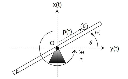
The structure of the proposed B&B system is shown in Fig. 1. Whereas its parameters value is listed in Table 1.
Consider the system with O (0; 0): center of rotation, Potential energy landmark at O, p: the position of the ball relative to O (m),  : angle of deviation of beam b from the horizontal (rad),
  : torque generated by the engine (Nm). The detailed parameters of the system [16] are selected. According to [16], the B&B mathematical model is as follow.
STT | Sign | Mean | Value | Unit |
1 |
| Constant torque of the motor | 0.0649 | N |
2 |
| Back EMF | 0.0649 | V/rad/s |
3 |
| Motor resistance | 6.8357 | Ω |
4 |
| Ball mass B | 0.045 | Kg |
5 |
| Beam mass b | 0.35 | Kg |
6 |
| Ball radius B | 0.011 | m |
7 |
| Beam length b | 0.34 | m |
| (1) |
| (2) |
Where:  : moment of inertia of the beam when rotating around its center,
  : moment of inertia of the ball when rotating around its center, g = 9.81 (m/
 ): gravitational acceleration.
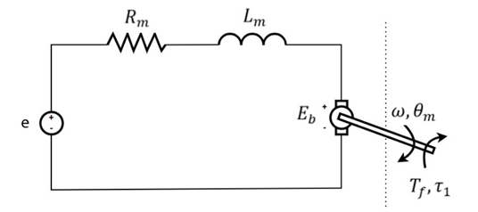
The system is often controlled by adjusting the voltage supplied to the motor. Therefore, the authors performed an additional step of converting the MMM of the system to the motor voltage. Consider the motor with structure:
The moment generated by the engine is calculated by the formula: Where Fig. 2: e (V): the voltage supplied to the motor,  (rad/s): angular velocity. Substituting (3) into (2), the MMM of the system is rewritten: Substituting (6) into (4), and (5); the MMM of the system is rewritten:
| (3) |
| (4) |
| (5) |
| (6) |
| (7) |
| (8) |
| (9) |
| (10) |
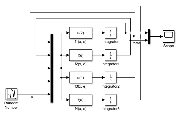
Fig. 3 shows the proposed B&B system in MATLAB/ Simulink which can be described as  : Matlab Fcn blocks, to represent equations (7), (8), (9), (10), Random Number: the authors are investigating the influence of e on the states of the B&B system, Scope: to view output values as a graph over time.
The authors conducted many surveys using the above method to accumulate experience in controlling the B&B system. The e values can be Constant, Sine Waves, Random, Line Function.
 when changing
Choose 4 input variables of the Fuzzy Controller including ball position p (m), ball speed  (m/s), beam deflection angle (rad), and angular velocity
  (rad/s). Beam b has a length of 0.3m, so
  < 0.15m. Therefore, the authors’ team choose a range for p of [-0.5; 0.5]. In ideal conditions, considering the case where ball B freely falls a distance equal to the length of beam b, we have the maximum velocity of ball:
  . In the case of the B&B system, the maximum velocity of ball B must be less than
  . Therefore, the authors choose the range of v to be [-3; 3]. Due to rotation limitations, the maximum deflection angle of beam b is 1.571 rad. The authors choose the range of as [-2; 2]. The selected motor has a maximum rotation speed of 200 rpm. Therefore, the maximum angular velocity that beam b can achieve is 20.91 rad/s. The authors choose the range of as [-21; 21]. Choose 1 output of the Fuzzy Controller as the power supplied to the PWM (motor control pulse chopper). The authors chose an output range is [-100; 100].
Standardization is not a mandatory step when building a Fuzzy Controller. However, people often do it to increase the reusability of that Fuzzy Controller or to be able to program PLCs, microprocessors later. Inputs and outputs are normalized to the value range [-1; 1]. Therefore, preprocessing values  and postprocessing
  are required. Chosen K values that come from experimentation. In the initial step, the authors choose based on the estimated range. Choose
  ,
, .
.
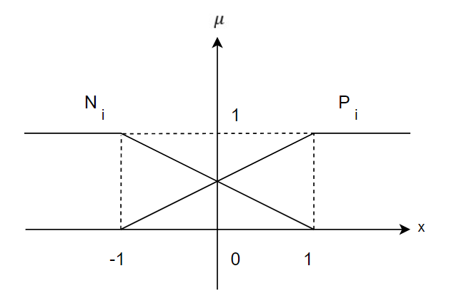
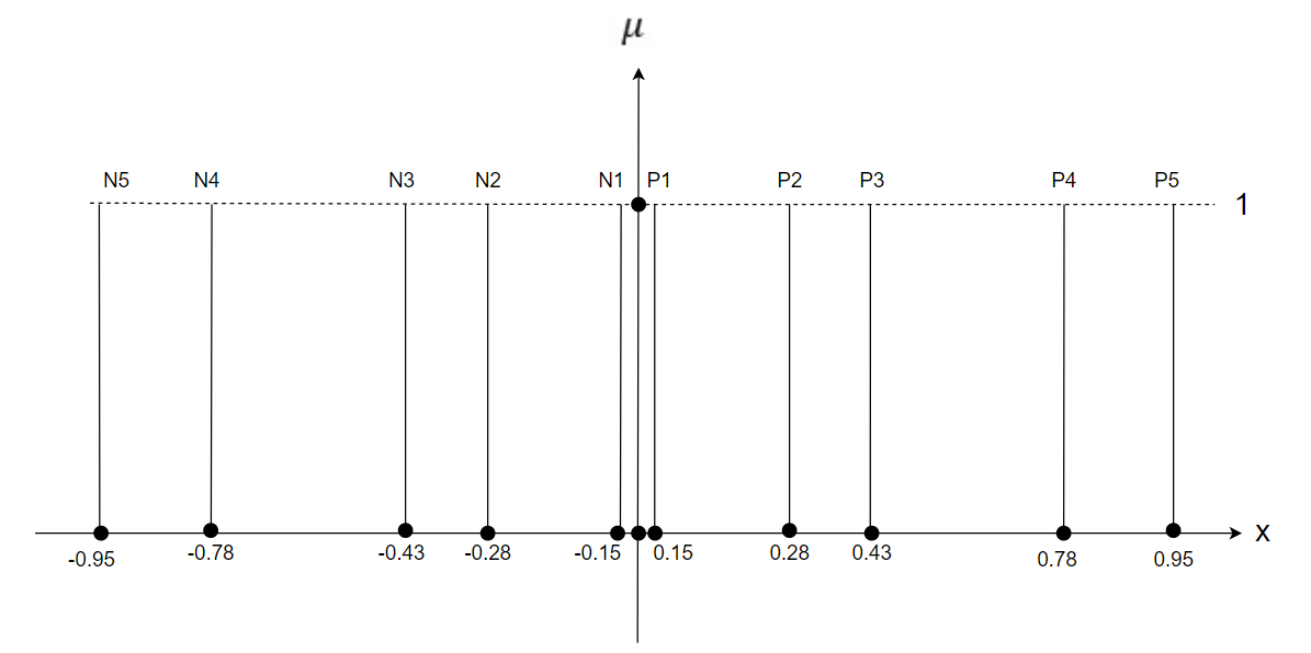
For each input, two triangular membership functions are considered for simplicity. In Fig. 4, the variable i ranges from 1 to 4, representing the membership function of input 1, 2, 3, and 4. The team of authors opted for the output of the Fuzzy Controller with 10 membership functions, where each membership function has a constant form Fig. 5.
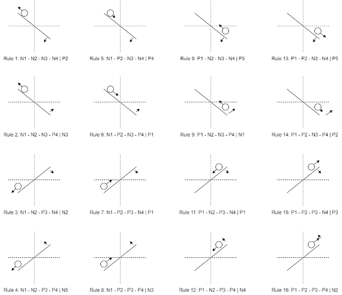
The authors proposed a table of 16 fuzzy rules Table 2. based on the control experience with the B&B system. In Table 2, P is positive, and N is negative. In Fig. 6, The authors present 16 cases corresponding to the 16 rules.
STT |
|
|
|
| Output |
1 | N | N | N | N | P2 |
2 | N | N | N | P | N3 |
3 | N | N | P | N | N2 |
4 | N | N | P | P | N5 |
5 | N | P | N | N | P4 |
6 | N | P | N | P | P1 |
7 | N | P | P | N | P1 |
8 | N | P | P | P | N3 |
9 | P | N | N | N | P3 |
10 | P | N | N | P | N1 |
11 | P | N | P | N | N1 |
12 | P | N | P | P | N4 |
13 | P | P | N | N | P5 |
14 | P | P | N | P | P2 |
15 | P | P | P | N | P3 |
16 | P | P | P | P | N2 |
Choose the Max-Prod inference method. Choose the centroid defuzzification method (COA). The fuzzy map is built according to the Takagi-Sugeno fuzzy model.
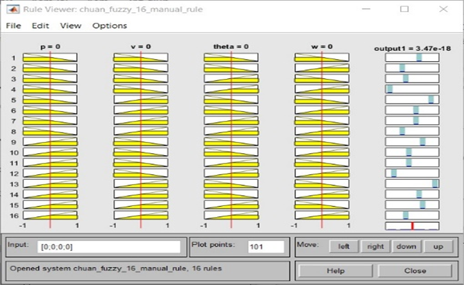
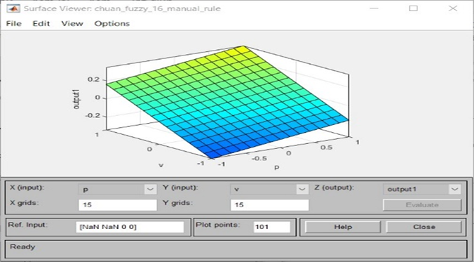
Using the “Fuzzy Logic Designer” tool in MATLAB, create a Fuzzy Logic Controller using the Sugeno method. The results obtained are shown in Fig. 7, Fig. 8.
To confirm the efficiency of a 16-rule Fuzzy controller, the author simulated its control of the B&B system by using MATLAB Simulink. Unfortunately, the results of the first simulation using the selected preprocessing-postprocessing coefficients were unsuccessful and unstable. The authors then retested the coefficients to better match reality. After investigation, they found that the post-processing coefficient was too small, resulting in a control signal that was also too small. The authors decided to increase the post-processing factor by ten times,  . Then, they re-simulated using the new coefficients.
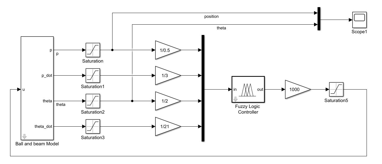
In Fig. 9, Ball and beam Model: The subsystem block describes the B&B system's MMM, Fuzzy Logic Controller – 16 Rules: Fuzzy Controller 16 rules, : The pre-processing block has been selected, : The post-processing block has been selected, Scope: to view system stability results over time.
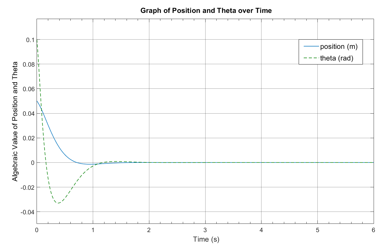
The simulation result is depicted in Fig. 10. To be more specific, we considered the stability criteria as steady-state error ( ), settling time (
 ), and overshoot (POT) in Table 3. Based on the outcome of the simulation, the authors' team has determined that the 16-rule Fuzzy Controller, which was designed based on control experience, is capable of effectively stabilizing the B&B system.
|
| POT | |
| 0 m | 1.75 s | -0.0014 m |
| 0 rad | 1.75 s | -0.033 rad |
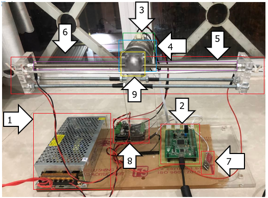
The authors used the B&B model of C205B laboratory, Ho Chi Minh City University of Technology and Education shown in Fig. 11, where:
(1) The 24V Power, (2) The Kit STM32F407 Discovery, (3) The Encoder, (4) The DC motor, (5) The Wiring resistance sensor, (6) The Beam, (7) The CP2021 UART, (8) The H Bridge, (9) The ball.
The authors experimented to test the efficacy of the Fuzzy Controller on a real B&B model. The initial control results, obtained using the selected preprocessing-postprocessing coefficients in the simulation, were observed to be unstable. Upon retesting, the authors discovered that the preprocessing factor was unsuitable, leading to distortion of the input signal to the Fuzzy Controller. As a result, the authors decided to modify the preprocessing coefficients to enhance performance.
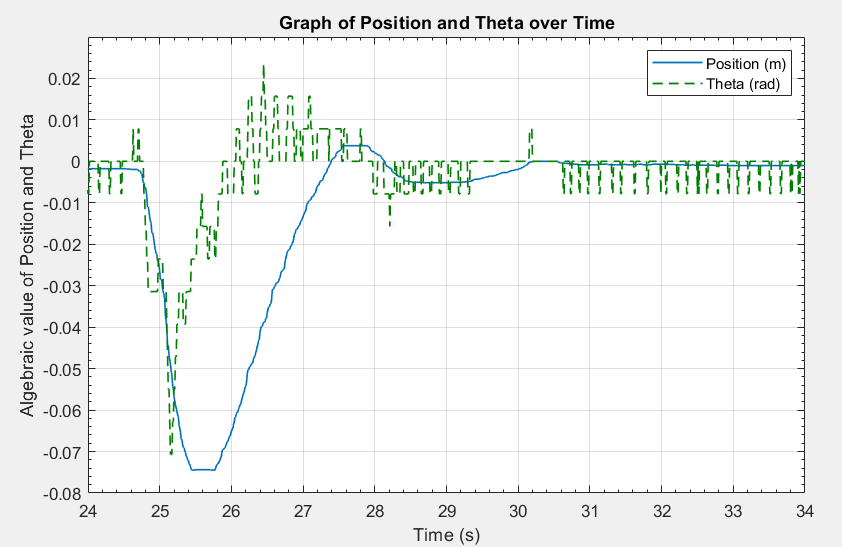
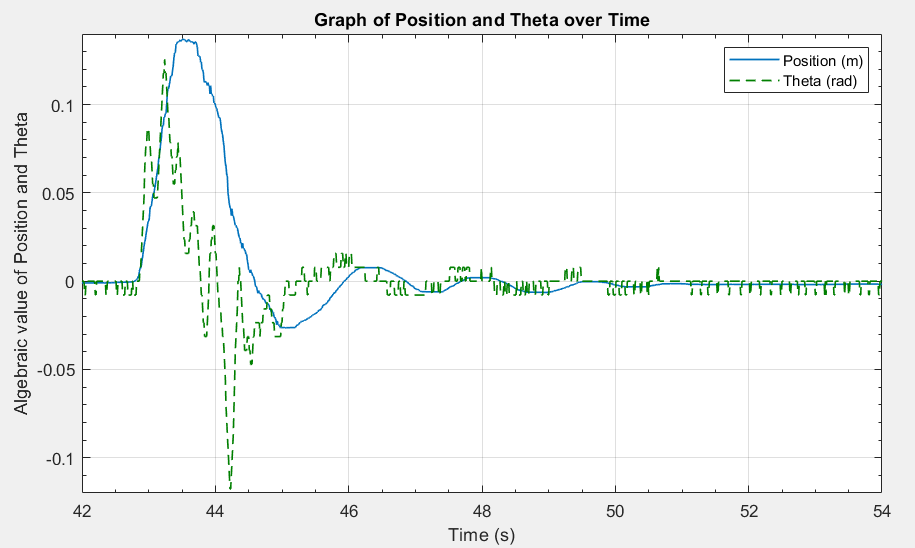
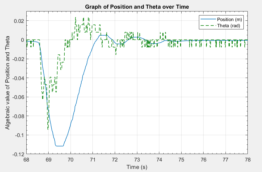
The authors have opted to modify the preprocess coefficients, effecting the following changes:  . The authors executed practical control utilizing a new set of coefficients which was implemented with the aid of the MATLAB Simulink application that was combined with the Waijung Blockset library to embed the control program for the STM32F407VG microcontroller. The control experiment was performed thrice, and the stable results obtained from the experiment are presented in Fig. 12, Fig. 13, and Fig. 14.
To be more specific, we considered the stability criteria as steady-state error (), settling time (), and overshoot (POT) in Table 4. Control results show that the 16-rule Fuzzy Controller can stabilize the B&B system well.
Time |
|
| POT |
1st (Innit at -0.075m; -0.07rad | 0.001m | 5s | 0.005m |
0.078rad | 5s | 0.022rad | |
2nd (Innit at 0.14 m; 0.12 rad) | 0.0006m | 7s | -0.025m |
0.078rad | 7.5s | -0.12rad | |
3rd (Innit at -0.11m; -0.1rad | 0.0005m | 6s | 0.005m |
0.078rad | 6s | 0.025rad |
The authors' team has successfully designed a 16-rule Fuzzy controller, which has demonstrated its effectiveness in stabilizing the B&B system both in simulation and experiment. This achievement highlights the viability of constructing a fuzzy controller for a complex system with unknown parameters or properties. Additionally, the Fuzzy Controller 16 rules have shown their flexibility in various conditions, remaining responsive despite differences between simulation and experiment. These promising results serve as a solid foundation for further research on the B&B system. Furthermore, the standardized 16-rule Fuzzy Controller can be adopted for similar systems, facilitating researchers' understanding of fuzzy algorithms and simplifying the design of fuzzy logic controllers.
The link video of the system's operation is shown at: https://www.youtube.com/watch?v=uCyq7vytVI4.
Minh-Quan Nguyen, Fuzzy Controller from Experts’ Rules for Middle Axis Ball and Beam